


Filter by
System of Measurement
Thread Size
Nut Type

Component
Thread Type
External Thread Size

Material
Length
Threaded Insert Type
Travel Distance per Turn
Dynamic Thrust Load Capacity
Thread Direction
Thread Spacing

RoHS
Export Control Classification Number (ECCN)
DFARS Specialty Metals
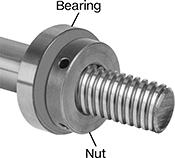
Fast-Travel Ball Screws and Nuts
 | 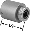 |
Ball Nuts, Externally Threaded Nut, Style B |
Multiple thread channels (also known as thread starts) create faster linear travel than ball screws with a single thread start. Internal ball bearings provide smooth low-friction travel in applications that require high speeds, accurate positioning, and repeatable movement. To ensure compatibility, select components that have the same thread size and number of thread starts. Ball nuts are furnished with a tube to keep ball bearings in place. Do not remove the tube until you are ready to install the nuts onto the screws.
Externally Threaded Ball Nuts—Right-Hand Threaded
|
Style B |
Carbon Steel—Carbon steel ball screws and nuts are case hardened, so they resist wear better than standard carbon steel. However, they are less corrosion resistant than black-oxide alloy steel screws and nuts.
Travel Distance per Turn—Travel distance per turn, also known as screw lead, is the distance a ball nut moves with one revolution of the ball screw.
Style | Thread Size | Lg., mm | Dia., mm | No. of Thread Starts | Travel Distance per Turn, mm | External Thread Size | Hardness | Dynamic Thrust Load Cap., lb. | Max. Backlash, mm | Temp. Range, ° F | Each | |||
|---|---|---|---|---|---|---|---|---|---|---|---|---|---|---|
Carbon Steel | ||||||||||||||
| B | M16 | 50 | 39 | 4 | 16 | M30 | Rockwell C56 | 1,500 | 0.04 | 32 to 150 | 4566N302 | 0000000 | ||
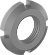
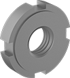
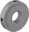
Bearing Nuts
 |
Carbon Steel Chamfered Face |
 |
Carbon Steel Stepped Face |
Often paired with spring lock washers to strengthen their hold, these bearing nuts—also known as shaft nuts—keep vibration from shifting bearings, bushings, pulleys, and gears on your threaded shaft or spindle. They have slotted sides, so you can tighten and loosen them with a spanner wrench or spanner socket.
Carbon Steel—Carbon steel bearing nuts are strong and resist wear.
Chamfered Face—Chamfered-face bearing nuts weigh less and produce less heat than stepped-face nuts.
Stepped Face—Use stepped-face bearing nuts with DIN 462 spring lock washers. You can also use them in pairs or with other bearing nuts. For the nut closer to the bearing, position the stepped face towards the bearing. All meet DIN standards for bearing lockout dimensions.
ISO 2982— Some chamfered-face bearing nuts meet ISO 2982 (formerly DIN 981), an international standard for bearing locknut dimensions. Their sizes correspond to SKF KM series. Use them with DIN 5406 spring lock washers.
Thread Spacing—When choosing your thread spacing, consider the precision of your application. The finer the threads, the more control you have when making adjustments.
Nuts | Bearing Lock Washers | Sockets | |||||||||||
|---|---|---|---|---|---|---|---|---|---|---|---|---|---|
Thread | |||||||||||||
Size | Spacing | OD, mm | Wd., mm | Specs. Met | For Lock Washer Specs. Met | Each | Each | Each | |||||
Carbon Steel | |||||||||||||
Chamfered Face | |||||||||||||
| M30 × 1.5 mm | Extra Fine | 45 | 7 | DIN 981, ISO 2982 | DIN 5406 | 3554N17 | 00000 | 90391A117 | 00000 | 5510N182 | 0000000 | ||
Stepped Face | |||||||||||||
| M30 × 1.5 mm | Extra Fine | 50 | 10 | DIN 1804 | DIN 462 | 3564N21 | 00000 | 90407A124 | 0000 | ——— | 0 | ||
Bearing Locknuts
 |
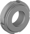 |
Carbon Steel |
With a nylon insert that grips your threaded shaft or spindle without damaging its threads, these locknuts—also called shaft nuts—hold bearings, bushings, gears, and pulleys prone to vibration tightly in place. They come as one piece, so you can easily clamp them onto your shaft or spindle. But, since they aren’t made entirely of metal, they don’t stand up to heat as well as all-metal locknuts. Slots in their sides mean you can tighten and loosen them with a spanner wrench or spanner socket. Their face is also chamfered to help keep the size and weight of your assembly at a minimum. All meet international standards for bearing locknut dimensions.
Zinc-Plated Carbon Steel—Zinc-plated carbon steel locknuts resist rusting from some moisture, but you shouldn’t use them with salt water or chemicals. They are strong and resist wear, though they don’t stand up to corrosion as well as 303 stainless steel locknuts.
Carbon Steel—All carbon steel locknuts are strong and resist wear, though they don’t stand up to corrosion as well as 303 stainless steel locknuts.
303 Stainless Steel—303 stainless steel locknuts resist corrosion better than carbon steel locknuts but aren’t as strong. They withstand washdowns and chemicals.
Thread Spacing—When choosing your thread spacing, consider the precision of your application. The finer the threads, the more control you have when making adjustments.
Thin-Profile Bearing Nuts
 |
 |
Thread | ||||||||
|---|---|---|---|---|---|---|---|---|
Size | Spacing | OD, mm | Wd., mm | Specs. Met | Each | |||
Carbon Steel | ||||||||
Stepped Face | ||||||||
| M30 × 1.5 mm | Extra Fine | 50 | 10 | DIN 1816 | 3549N22 | 000000 | ||
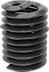
Helical Threaded Inserts with Installation Tools
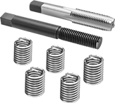 |
Installation Tool and Through-Hole Tap |
Quickly restore stripped threads—these inserts come with through-hole taps and installation tools. The tough coils on these inserts expand once installed to anchor in a tapped hole.
Pronged—The prong attaches to an installation tool for precise control as you drive inserts in. Remove the prong with a punch or break-off tool before inserting a screw.
18-8 Stainless Steel—The choice for wet and outdoor environments, these inserts resist rust and mild chemicals.
Thread Size | Installed Lg., mm | Drill Bit Size | For Max. Hole Dia. | No. of Inserts Included | Includes | Each | |||
|---|---|---|---|---|---|---|---|---|---|
Pronged | |||||||||
18-8 Stainless Steel | |||||||||
| M30 x 3.5 mm | 45 | 1 1/4" | 1.250" | 5 | Installation Tool Through-Hole Tap | 91732A972 | 0000000 | ||
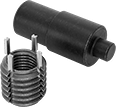
Finish-Your-Own Key-Locking Threaded Inserts for Soft Metal
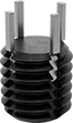 |  |
Tap the thread size you need into the solid body of these inserts. They’re a great choice when you need a custom combination of internal thread size and external diameter. Use them to repair or add new threads in soft metal, such as aluminum. They can also plug threaded holes without the hassle of welding. Keys on the inserts drive into material to prevent slipping and rotating in the hole.
To install, drill and tap a hole in your material. Then, thread the insert onto the installation tool and screw it into the hole. Place the tool over the keys and hit it with a hammer to drive them in.
Black Phosphate-Coated Steel—These inserts resist occasional moisture.
%20--%3e%3cg%3e%3cg%20id='Layer_1'%3e%3cpath%20class='cls-1'%20d='M68,27.2c-14.6,0-26.4,11.7-26.4,26.3,0,7,2.8,13.7,7.7,18.7v44.8l18.8-16.1,18.7,16.1v-44.9c10.3-10.3,10.3-27,0-37.3-5-4.9-11.7-7.7-18.7-7.7h0ZM81.3,105l-13.2-11.4-13.2,11.4v-28.7c8.2,4.8,18.3,4.8,26.5,0v28.7ZM76.2,70.8c-5.2,2.5-11.2,2.5-16.4,0-9.5-4.5-13.5-15.9-9-25.4,4.5-9.5,15.9-13.5,25.4-9,9.5,4.5,13.5,15.9,9,25.4-1.9,4-5.1,7.1-9,9Z'/%3e%3cpath%20class='cls-2'%20d='M5.8,95.5c-1.2,0-2.1-1-2.1-2.1,0,0,0,0,0,0V29.4h20.9c2.1,0,3.8-1.7,3.8-3.8V3.7c.2,0,.4,0,.5,0h37.5c1.2,0,2.1,1,2.1,2.1v18.6c1.2,0,2.5.1,3.7.3V5.8C72.2,2.6,69.6,0,66.4,0H28.9c-1.5,0-3,.6-4.1,1.7h-.1c0,.1-23,23.2-23,23.2-1.1,1.1-1.7,2.6-1.7,4.1v64.3c0,3.2,2.6,5.8,5.8,5.8h41.7v-3.7H5.8ZM24.7,7.1v18.7H6L24.7,7.1Z'/%3e%3c/g%3e%3c/g%3e%3c/svg%3e)
Certificates with a traceable lot number are available for these products. Download certificates from ORDER HISTORY after your order ships.
Key-Locking Threaded Inserts with Installation Tools
 |
Paired with the right tool for installation, these inserts create strong threads in soft metal, such as aluminum. They have keys that drive into material to prevent inserts from slipping and rotating in the hole.
Standard Wall—Stronger than thin-wall inserts, these are your go-to choice for threading most holes.
Black Phosphate-Coated Steel—These inserts resist occasional moisture.
18-8 Stainless Steel—The choice for wet and outdoor environments, these inserts resist rust and mild chemicals.
Thread Size | For Tap Thread Size | Installed Lg., mm | Drill Bit Size, mm | For Max. Hole Dia., mm | No. of Locking Keys | No. of Inserts Included | Each | |||
|---|---|---|---|---|---|---|---|---|---|---|
Standard Wall | ||||||||||
Black Phosphate-Coated Steel | ||||||||||
| M20 x 1.5 mm | M30 x 2 mm | 30 | 28 | 28 | 4 | 3 | 90245A331 | 000000 | ||
| M20 x 2.5 mm | M30 x 2 mm | 30 | 28 | 28 | 4 | 3 | 90245A326 | 00000 | ||
18-8 Stainless Steel | ||||||||||
| M20 x 1.5 mm | M30 x 2 mm | 30 | 28 | 28 | 4 | 3 | 93715A485 | 000000 | ||
| M20 x 2.5 mm | M30 x 2 mm | 30 | 28 | 28 | 4 | 3 | 93715A480 | 000000 | ||
Screw-Locking Helical Threaded Inserts
 |
Pronged |
The irregularly shaped threads tightly grip screws to prevent them from loosening or backing out under vibration. Use these inserts to create or repair threads in pumps and other machinery that shakes and rattles. Also known as Heli-Coil inserts.
Installation requires a drill bit, a helical insert tap, and an installation tool.
Pronged—The prong attaches to an installation tool for precise control as you drive inserts in. Remove the prong with a punch or break-off tool before inserting a screw.
18-8 Stainless Steel—The choice for wet and outdoor environments, these inserts resist rust and mild chemicals.
Helical Threaded Inserts
 |
Pronged |
Restore, reinforce, or create threads in metal. The tough coils on these inserts expand once installed to anchor in a tapped hole. Also known as Heli-Coil inserts, they're often used in engine heads and machinery housings where strong connections are critical. Unlike threadlocking inserts, you can remove and reuse them without them losing their strength.
Installation requires a drill bit, a helical insert tap, and an installation tool.
Pronged—The prong attaches to an installation tool for precise control as you drive inserts in. Remove the prong with a punch or break-off tool before inserting a screw.
18-8 Stainless Steel—The choice for wet and outdoor environments, these inserts resist rust and mild chemicals.
Inserts | Through-Hole Taps | Closed-End Hole Taps | Installation Tools | Inserts with Installation Tools | ||||||||||||||
|---|---|---|---|---|---|---|---|---|---|---|---|---|---|---|---|---|---|---|
Thread Size | Installed Lg., mm | Drill Bit Size | For Max. Hole Dia. | Specs. Met | Pkg. Qty. | Pkg. | Each | Each | Each | No. of Inserts Included | Each | |||||||
Pronged | ||||||||||||||||||
18-8 Stainless Steel | ||||||||||||||||||
| M30 x 3.5 mm | 45 | 1 7/32" | 1.219" | SAE MA3279-183 | 1 | 92450A145 | 00000 | 92450A345 | 0000000 | 91709A350 | 0000000 | 92450A192 | 000000 | 5 | 91732A972 | 0000000 | ||
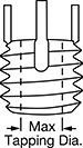
Key-Locking Threaded Inserts for Soft Metal
 |
Add strong threads in soft metal, such as aluminum. The keys on these inserts drive into holes to hold more securely than thread-locking or helical inserts. They prevent slipping and rotating, so they’re stable enough for use in vehicle or aerospace parts that experience heavy vibration. These inserts are comparable to Keensert inserts.
To install, drill and tap a hole in your material. Then, thread the insert onto the installation tool and screw it into the hole. Place the tool over the keys and hit it with a hammer to drive them in.
Standard Wall—Stronger than thin-wall inserts, these are your go-to choice for threading most holes.
Black Phosphate-Coated Steel—These inserts resist occasional moisture.
18-8 Stainless Steel—The choice for wet and outdoor environments, these inserts resist rust and mild chemicals.
Inserts | Installation Tools | Inserts with Installation Tools | |||||||||||||
|---|---|---|---|---|---|---|---|---|---|---|---|---|---|---|---|
Each | |||||||||||||||
Thread Size | For Tap Thread Size | Installed Lg., mm | Drill Bit Size, mm | For Max. Hole Dia., mm | No. of Locking Keys | 1-9 | 10-Up | Each | No. of Inserts Included | Each | |||||
Standard Wall | |||||||||||||||
Black Phosphate-Coated Steel | |||||||||||||||
| M20 x 1.5 mm | M30 x 2 mm | 30 | 28 | 28 | 4 | 90245A205 | 000000 | 000000 | 94010A355 | 000000 | 3 | 90245A331 | 000000 | ||
| M20 x 2.5 mm | M30 x 2 mm | 30 | 28 | 28 | 4 | 90245A201 | 00000 | 00000 | 94010A355 | 00000 | 3 | 90245A326 | 00000 | ||
18-8 Stainless Steel | |||||||||||||||
| M20 x 1.5 mm | M30 x 2 mm | 30 | 28 | 28 | 4 | 93715A675 | 00000 | 00000 | 94010A355 | 00000 | 3 | 93715A485 | 000000 | ||
| M20 x 2.5 mm | M30 x 2 mm | 30 | 28 | 28 | 4 | 93715A670 | 00000 | 00000 | 94010A355 | 00000 | 3 | 93715A480 | 000000 | ||
