


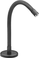
Ball-Grip Positioning Arms
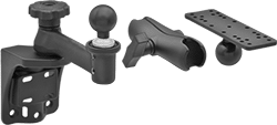 | 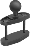 | 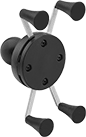 | 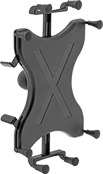 |
Arm Built with Rotating Complete Arm with Ball, Rigid Connector, and Universal Mounting Plate | Clamp-On Rectangular Bar Mount Bases, Style D | For Smartphones—Handheld Device Grips, Style E | For Tablets—Handheld Device Grips, Style F |
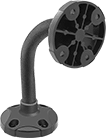 | 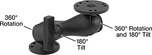 |
Any-Which-Way | Rotating/Tilting Arm |
Base | Attaching End | ||||||||||||||||
|---|---|---|---|---|---|---|---|---|---|---|---|---|---|---|---|---|---|
Max. Projection | Ht. | Max. Load Cap., lb. | Material | Color | Mounting Fasteners Included | Dia. | No. of Mounting Holes | Mounting Hole Dia. | Plate Dia. | Mounting Hole Dia. | Range of Motion | Max. Tilt Range of Motion | No. of Mounting Holes | Each | |||
Any-Which-Way | |||||||||||||||||
| — | 7 3/8" | 1 | Plastic | Black | No | 2 1/2" | 4 | 13/64" | 2 1/2" | 13/64" | — | — | 4 | 5031T132 | 000000 | ||
Rotating/Tilting | |||||||||||||||||
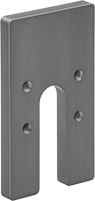
| 7 1/4" | — | 3 | Powder-Coated Aluminum | Black | No | 2 7/16" | 7 | 3/16" | 2 7/16" | 3/16" | 360° | 180° | 7 | 5031T61 | 00000 | ||
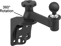 | 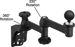 |
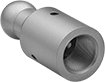
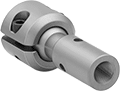
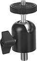
Rotating-Ball Arm | Extended-Reach Rotating Ball Arm |
Base | ||||||||||||||||
|---|---|---|---|---|---|---|---|---|---|---|---|---|---|---|---|---|
Max. Projection | Ht. | Ball Dia. | Max. Load Cap., lb. | Material | Ball Material | Color | Mounting Fasteners Included | Lg. | Wd. | No. of Mounting Holes | Mounting Hole Dia. | Max. Range of Motion | Each | |||
Rotating with Ball | ||||||||||||||||
| 9 1/4" | 9" | 1 1/2" | 3 | Powder-Coated Aluminum | Rubber | Black | No | 4 3/4" | 3 7/8" | 6 | 11/32" | — | 5031T77 | 0000000 | ||
Extended-Reach Rotating with Ball | ||||||||||||||||
| 15 1/4" | 11 1/4" | 1 1/2" | 3 | Powder-Coated Aluminum | Rubber | Black | No | 4 3/4" | 3 7/8" | 6 | 11/32" | 330° | 5031T25 | 000000 | ||
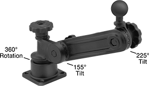 |
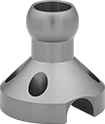
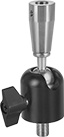
Rotating/Tilting-Ball Arm |
Base | ||||||||||||||||
|---|---|---|---|---|---|---|---|---|---|---|---|---|---|---|---|---|
Max. Projection | Ht. | Ball Dia. | Max. Load Cap., lb. | Material | Ball Material | Color | Mounting Fasteners Included | Lg. | Wd. | No. of Mounting Holes | Mounting Hole Dia. | Max. Tilt Range of Motion | Each | |||
Rotating/Tilting with Ball | ||||||||||||||||
| 14 1/2" | 14 1/2" | 1 1/2" | 3 | Powder-Coated Aluminum | Rubber | Black | No | 3 7/16" | 3 7/16" | 4 | 11/32" | 155° | 5031T26 | 0000000 | ||
|
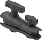
Style D |
Base | |||||||||||||
|---|---|---|---|---|---|---|---|---|---|---|---|---|---|
Style | Clamping Distance Range | Ht. | Ball Dia. | Max. Load Cap., lb. | Material | Ball Material | Color | Lg. | Wd. | Each | |||
Rotate, Tilt, Side to Side, In/Out | |||||||||||||
| D | 0" to 2 1/2" | 2 1/2" | 1 1/2" | 3 | Powder-Coated Aluminum | Rubber | Black | 3 1/8" | 1 1/4" | 5031T28 | 000000 | ||
 |
Ht. | Ball Dia. | Max. Load Cap., lb. | Material | Ball Material | Color | Base Dia. | Each | |||
|---|---|---|---|---|---|---|---|---|---|---|
Rotate, Tilt, Side to Side, In/Out | ||||||||||
| 2 1/4" | 1 1/2" | 0.5 | Aluminum | Rubber | Black | 2 1/2" | 5031T56 | 000000 | ||
 |
Lg. | For Ball Dia. | Max. Load Cap., lb. | Material | Color | Each | |||
|---|---|---|---|---|---|---|---|---|
Rotate, Tilt, Side to Side, In/Out | ||||||||
| 5 1/4" | 1"; 1 1/2" | 1 | Plastic | Black | 5031T137 | 000000 | ||
|
Style E |
Style | For Diag. Screen Size | Ball Dia. | Max. Load Cap., lb. | Material | Ball Material | Color | Each | |||
|---|---|---|---|---|---|---|---|---|---|---|
Rotate, Tilt, Side to Side, In/Out | ||||||||||
| E | 4.5" to 6.2" | 1" | 1 | Plastic | Rubber | Black | 5031T138 | 000000 | ||
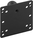 |
Monitor |
Mounting | |||||||||||||
|---|---|---|---|---|---|---|---|---|---|---|---|---|---|
For Mounting | Wd. | Ht. | Ball Dia. | Max. Load Cap., lb. | Material | Ball Material | Color | Fasteners Included | Monitor Hole Pattern Compatibility | Each | |||
Rotate, Tilt, Side to Side, In/Out | |||||||||||||
| Monitor | 4 3/4" | 4 3/4" | 1 1/2" | 3 | Powder-Coated Aluminum | Rubber | Black | No | VESA 100 × 100, VESA 75 × 75 | 5031T12 | 000000 | ||
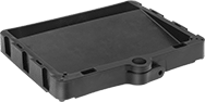 |
Mounting | ||||||||||||
|---|---|---|---|---|---|---|---|---|---|---|---|---|
Lg. | Wd. | For Ball Dia. | Max. Load Cap., lb. | Material | Color | Fasteners Included | No. of Holes | Hole Dia. | Each | |||
Rotate, Tilt, Side to Side, In/Out | ||||||||||||
| 10" | 13" | 1 1/2" | 1 | Plastic | Black | No | 4 | 11/64" | 5031T141 | 000000 | ||
Any-Which-Way Positioning Arms
 | |
End with Threaded Stud |
Attaching End | |||||||||||
|---|---|---|---|---|---|---|---|---|---|---|---|
Max. Projection | Base Mounting Thread Size | Max. Load Cap., lb. | Material | Color | Includes | Mounting Thread Size | Mounting Thread Type | Each | |||
Rotate, Tilt, Side to Side, In/Out | |||||||||||
| 6" | 1/4"-20 | 4 | Vinyl-Coated Steel | Black | Two 1/4"-20 Threaded Studs, Threadlocker | 1/4"-20 | UNC | 50035A21 | 000000 | ||
| 9" | 1/4"-20 | 3.5 | Vinyl-Coated Steel | Black | Two 1/4"-20 Threaded Studs, Threadlocker | 1/4"-20 | UNC | 50035A22 | 00000 | ||
| 12" | 1/4"-20 | 3 | Vinyl-Coated Steel | Black | Two 1/4"-20 Threaded Studs, Threadlocker | 1/4"-20 | UNC | 50035A23 | 00000 | ||
| 15" | 1/4"-20 | 2 | Vinyl-Coated Steel | Black | Two 1/4"-20 Threaded Studs, Threadlocker | 1/4"-20 | UNC | 50035A24 | 00000 | ||
| 18" | 1/4"-20 | 2.5 | Vinyl-Coated Steel | Black | Two 1/4"-20 Threaded Studs, Threadlocker | 1/4"-20 | UNC | 50035A25 | 00000 | ||
| 24" | 1/4"-20 | 1.5 | Vinyl-Coated Steel | Black | Two 1/4"-20 Threaded Studs, Threadlocker | 1/4"-20 | UNC | 50035A26 | 00000 | ||
| 30" | 1/4"-20 | 0.8 | Vinyl-Coated Steel | Black | Two 1/4"-20 Threaded Studs, Threadlocker | 1/4"-20 | UNC | 50035A31 | 00000 | ||
| 36" | 1/4"-20 | 0.6 | Vinyl-Coated Steel | Black | Two 1/4"-20 Threaded Studs, Threadlocker | 1/4"-20 | UNC | 50035A32 | 00000 | ||
 |  |
Threaded Hole |
Attaching End | ||||||||||
|---|---|---|---|---|---|---|---|---|---|---|
Max. Projection | Base Mounting Thread Size | Max. Load Cap., lb. | Material | Color | Mounting Thread Size | Mounting Thread Type | Each | |||
Rotate, Tilt, Side to Side, In/Out | ||||||||||
| 6" | 5/8"-27 | 3 | Vinyl-Coated Steel | Black | 5/8"-27 | UNS | 50035A691 | 00000 | ||
| 13" | 5/8"-27 | 1 | Vinyl-Coated Steel | Black | 5/8"-27 | UNS | 50035A692 | 00000 | ||
| 19" | 5/8"-27 | 1 | Vinyl-Coated Steel | Black | 5/8"-27 | UNS | 50035A693 | 00000 | ||
 |  |
Threaded Stud |
Attaching End | ||||||||||
|---|---|---|---|---|---|---|---|---|---|---|
Max. Projection | Base Mounting Pipe Size | Max. Load Cap., lb. | Material | Color | Mounting Pipe Size | Mounting Thread Type | Each | |||
Rotate, Tilt, Side to Side, In/Out | ||||||||||
| 9" | 1/8 | 2 | Vinyl-Coated Steel | Black | 1/8 | NPSM | 50035A681 | 00000 | ||
| 15" | 1/8 | 1 | Vinyl-Coated Steel | Black | 1/8 | NPSM | 50035A682 | 0000 | ||
| 24" | 1/8 | 1 | Vinyl-Coated Steel | Black | 1/8 | NPSM | 50035A683 | 00000 | ||
| |
End with Threaded Stud |
Base | Attaching End | ||||||||||||||
|---|---|---|---|---|---|---|---|---|---|---|---|---|---|---|---|
Max. Projection | Max. Load Cap., lb. | Material | Color | Mounting Fasteners Included | Lg. | Wd. | No. of Mounting Holes | Mounting Hole Dia. | Includes | Mounting Thread Size | Mounting Thread Type | Each | |||
Rotate, Tilt, Side to Side, In/Out | |||||||||||||||
| 9" | 3 | Vinyl-Coated Steel | Black | Yes | 2" | 1" | 2 | 0.275" | One 3/8"-16 Threaded Stud, Threadlocker | 3/8"-16 | UNC | 50035A33 | 000000 | ||
| 9" | 3.5 | Vinyl-Coated Steel | Black | No | 2" | 1" | 2 | 0.275" | One 1/4"-20 Threaded Stud, Threadlocker | 1/4"-20 | UNC | 49985A29 | 00000 | ||
| 16" | 2.5 | Vinyl-Coated Steel | Black | No | 2" | 1" | 2 | 0.275" | One 1/4"-20 Threaded Stud, Threadlocker | 1/4"-20 | UNC | 49985A31 | 00000 | ||
| 16" | 2.5 | Vinyl-Coated Steel | Black | No | 2" | 1" | 2 | 0.275" | One 3/8"-16 Threaded Stud, Threadlocker | 3/8"-16 | UNC | 49985A27 | 00000 | ||
| 24" | 1.5 | Vinyl-Coated Steel | Black | No | 2" | 1" | 2 | 0.275" | One 1/4"-20 Threaded Stud, Threadlocker | 1/4"-20 | UNC | 49985A32 | 00000 | ||
| 24" | 1.5 | Vinyl-Coated Steel | Black | No | 2" | 1" | 2 | 0.275" | One 3/8"-16 Threaded Stud, Threadlocker | 3/8"-16 | UNC | 49985A28 | 00000 | ||
 |
Base | Attaching End | ||||||||||||
|---|---|---|---|---|---|---|---|---|---|---|---|---|---|
Max. Projection | For Max. Mounting Surface Thk. | Max. Load Cap., lb. | Material | Color | Lg. | Wd. | Mounting Thread Size | Mounting Thread Type | Features | Each | |||
Rotate, Tilt, Side to Side, In/Out | |||||||||||||
| 16" | 2" | 2.5 | Vinyl-Coated Steel | Black | 2" | 2" | 3/8"-16 | UNC | Padded Base Clamp | 49985A17 | 000000 | ||
| 24" | 2" | 1.5 | Vinyl-Coated Steel | Black | 2" | 2" | 3/8"-16 | UNC | Padded Base Clamp | 49985A16 | 00000 | ||
| |
End with Threaded Stud |
Base | Attaching End | |||||||||||||
|---|---|---|---|---|---|---|---|---|---|---|---|---|---|---|
Max. Projection | For Max. Mounting Surface Thk. | Max. Load Cap., lb. | Material | Color | Lg. | Wd. | Includes | Mounting Thread Size | Mounting Thread Type | Features | Each | |||
Rotate, Tilt, Side to Side, In/Out | ||||||||||||||
| 9" | 2" | 3 | Vinyl-Coated Steel | Black | 2" | 1 5/8" | One 3/8"-16 Threaded Stud, Threadlocker | 3/8"-16 | UNC | Padded Base Clamp | 50035A34 | 000000 | ||
| 9" | 2" | 3.5 | Vinyl-Coated Steel | Black | 2 7/8" | 2" | One 1/4"-20 Threaded Stud, Threadlocker | 1/4"-20 | UNC | — | 49985A21 | 00000 | ||
| 16" | 2" | 2.5 | Vinyl-Coated Steel | Black | 2 7/8" | 2" | One 1/4"-20 Threaded Stud, Threadlocker | 1/4"-20 | UNC | — | 49985A22 | 00000 | ||
| 24" | 2" | 1.5 | Vinyl-Coated Steel | Black | 2 7/8" | 2" | One 1/4"-20 Threaded Stud, Threadlocker | 1/4"-20 | UNC | — | 49985A23 | 00000 | ||
 | |
End with Threaded Stud |
Attaching End | ||||||||||||
|---|---|---|---|---|---|---|---|---|---|---|---|---|
Max. Projection | Max. Pull, lbf | Max. Load Cap., lb. | Material | Color | Base Dia. | Includes | Mounting Thread Size | Mounting Thread Type | Each | |||
Rotate, Tilt, Side to Side, In/Out | ||||||||||||
| 9" | 100 | 3 | Vinyl-Coated Steel | Black | 3" | One 3/8"-16 Threaded Stud, Threadlocker | 3/8"-16 | UNC | 50035A35 | 000000 | ||
| 9" | 100 | 3.5 | Vinyl-Coated Steel | Black | 3 1/4" | One 1/4"-20 Threaded Stud, Threadlocker | 1/4"-20 | UNC | 49985A24 | 00000 | ||
| 16" | 100 | 2.5 | Vinyl-Coated Steel | Black | 3 1/4" | One 1/4"-20 Threaded Stud, Threadlocker | 1/4"-20 | UNC | 49985A25 | 00000 | ||
| 24" | 100 | 1.5 | Vinyl-Coated Steel | Black | 3 1/4" | One 1/4"-20 Threaded Stud, Threadlocker | 1/4"-20 | UNC | 49985A26 | 00000 | ||
Heavy Duty Ball-Grip Positioning Arms
 |
Arm Built with Base, Two Straight Connectors, Straight Link, Locking Handle, and Sensor Mount |
 |
Sensor Mounting Adapters, Style E |
 |
Sensor Mounting Adapters, Style F |
 |
For T-Slot Rail | Mounting | |||||||||||||
|---|---|---|---|---|---|---|---|---|---|---|---|---|---|---|
Ht. | Profile | Dia. | ID | Lg. | Max. Load Cap., lb. | Material | Color | Fasteners Included | No. of Holes | Hole Dia. | Each | |||
Rotate, Tilt, Side to Side, In/Out | ||||||||||||||
| 1", 1 1/2" | Single | 2 1/2" | 7/8" | 2 1/2" | 30 | Anodized Aluminum | Blue | Yes | 4 | 1/4" | 1530N11 | 000000 | ||
 |
Mounting | ||||||||||
|---|---|---|---|---|---|---|---|---|---|---|
Lg. | Wd. | Max. Load Cap., lb. | Material | Color | Fasteners Included | No. of Holes | Each | |||
Rotate, Tilt, Side to Side, In/Out | ||||||||||
| 4 5/16" | 2 1/2" | 30 | Anodized Aluminum | Blue | Yes | 4 | 1530N24 | 000000 | ||
 |
Mounting | |||||||||||
|---|---|---|---|---|---|---|---|---|---|---|---|
Lg. | Wd. | Max. Load Cap., lb. | Material | Color | Fasteners Included | Pattern Compatibility | No. of Holes | Each | |||
Rotate, Tilt, Side to Side, In/Out | |||||||||||
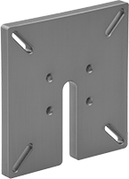
| 4 1/2" | 4 1/2" | 30 | Anodized Aluminum | Blue | Yes | VESA 100 × 100 VESA 75 × 75 | 4 | 1530N27 | 000000 | ||
| |
Style E | Style F |
Style | For Sensor/Switch OD, mm | Dia. | Lg. | Max. Load Cap., lb. | Material | Color | Each | |||
|---|---|---|---|---|---|---|---|---|---|---|
Rotate, Tilt, Side to Side, In/Out | ||||||||||
| E | 18 | 1 11/32" | 3 3/4" | 30 | Anodized Aluminum | Blue | 1530N26 | 000000 | ||
| E | 30 | 1 3/4" | 3 3/4" | 30 | Anodized Aluminum | Blue | 1530N25 | 00000 | ||
| F | 8 | 3/4" | 2 1/4" | 30 | Anodized Aluminum | Blue | 1530N29 | 00000 | ||
| F | 12 | 3/4" | 2 1/4" | 30 | Anodized Aluminum | Blue | 1530N28 | 00000 | ||
 |
Mounting Stud | ||||||||
|---|---|---|---|---|---|---|---|---|
Lg. | Material | Color | Thread Size | Lg. | Each | |||
Rotate, Tilt, Side to Side, In/Out | ||||||||
| 2" | Steel | Black | 10-24 | 1" | 1530N14 | 000000 | ||
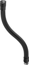
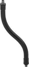
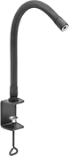
Bend-and-Stay Positioning Arms
 |
Base | Attaching End | |||||||||||||||
|---|---|---|---|---|---|---|---|---|---|---|---|---|---|---|---|---|
Max. Projection | Dia. | Max. Load Cap., lb. | Material | Color | Mount Type | Mounting Thread Size | Mounting Hole Thread Type | Mounting Fasteners Included | Mount Type | Mounting Thread Size | Mounting Thread Type | Mounting Fasteners Included | Each | |||
| 6" | 5/8" | 20 | Vinyl-Coated Copper | Black | Threaded Hole | 3/8"-24 | UNF | No | Threaded Hole | 3/8"-24 | UNF | No | 3883N111 | 000000 | ||
| 9" | 5/8" | 7 | Vinyl-Coated Copper | Black | Threaded Hole | 3/8"-24 | UNF | No | Threaded Hole | 3/8"-24 | UNF | No | 3883N112 | 00000 | ||
| 12" | 5/8" | 5 | Vinyl-Coated Copper | Black | Threaded Hole | 3/8"-24 | UNF | No | Threaded Hole | 3/8"-24 | UNF | No | 3883N113 | 00000 | ||
| 18" | 5/8" | 3 | Vinyl-Coated Copper | Black | Threaded Hole | 3/8"-24 | UNF | No | Threaded Hole | 3/8"-24 | UNF | No | 3883N114 | 00000 | ||
| 24" | 5/8" | 2.5 | Vinyl-Coated Copper | Black | Threaded Hole | 3/8"-24 | UNF | No | Threaded Hole | 3/8"-24 | UNF | No | 3883N115 | 00000 | ||
| 30" | 5/8" | 2 | Vinyl-Coated Copper | Black | Threaded Hole | 3/8"-24 | UNF | No | Threaded Hole | 3/8"-24 | UNF | No | 3883N116 | 00000 | ||
| 36" | 5/8" | 0.5 | Vinyl-Coated Copper | Black | Threaded Hole | 3/8"-24 | UNF | No | Threaded Hole | 3/8"-24 | UNF | No | 3883N117 | 00000 | ||
 |
Attaching End | Arm Attaching End | ||||||||||||||
|---|---|---|---|---|---|---|---|---|---|---|---|---|---|---|---|
Lg. | Range of Motion | Max. Tilt Range of Motion | Mounting Thread Size | Mounting Thread Type | Max. Load Cap., lb. | Body Material | Color | Mount Type | Mounting Thread Size | Mounting Thread Type | Features | Each | |||
Threaded Stud | |||||||||||||||
| 2 1/2" | 360° | 90° | 1/4"-20 | UNC | 6 | Anodized Aluminum | Black | Threaded Stud | 3/8"-24 | UNF | Locking Knob, Rubber-Padded Camera Seat | 3883N125 | 000000 | ||
 |
Attaching End | Arm Attaching End | |||||||||||||||
|---|---|---|---|---|---|---|---|---|---|---|---|---|---|---|---|---|
Lg. | Range of Motion | Max. Tilt Range of Motion | Mounting Thread Size | Mounting Thread Type | Mounting Fasteners Included | Max. Load Cap., lb. | Material | Color | Mount Type | Mounting Thread Size | Mounting Thread Type | Features | Each | |||
Threaded Hole | ||||||||||||||||
| 3 7/8" | 360° | 90° | 3/8"-24 | UNF | Yes | 6 | Anodized Aluminum | Black | Threaded Stud | 3/8"-24 | UNF | Locking Knob | 3883N119 | 000000 | ||
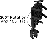
Mobile Device Mounts
 |  |
Clamp-On Pipe Mount Shown Installed |
Base | ||||||||||||
|---|---|---|---|---|---|---|---|---|---|---|---|---|
For Diag. Screen Size | Display Ht. | Clamping Distance Range | Max. Projection | Max. Load Cap. | Material | Color | Lg. | Wd. | Each | |||
Rotate, Tilt, Side to Side, Up and Down, In and Out | ||||||||||||
| 5.5" to 6.9" | 0" to 1 5/8" | 5/8" to 1 1/8" | 5" | Not Rated | Plastic | Black | 3 9/16" | 1 1/8" | 5943N15 | 000000 | ||
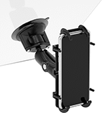 |  |
Suction Mount Shown Installed |
Projection | Attaching End | ||||||||||||
|---|---|---|---|---|---|---|---|---|---|---|---|---|---|
For Diag. Screen Size | Display Ht. | Min. | Max. | Max. Load Cap., lb. | Material | Color | Base Dia. | Range of Motion | Max. Tilt Range of Motion | Each | |||
Rotate, Tilt, Side to Side, Up and Down, In and Out | |||||||||||||
| 5.5" to 6.9" | 3/8" to 7 5/16" | 6" | 9 5/16" | 1 | Plastic | Black | 3 5/16" | 360° | 180° | 5943N16 | 000000 | ||
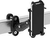 |  |
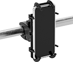
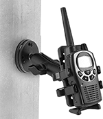
Clamp-On Rectangular-Bar Mount Shown Installed |
Projection | For Device | Base | Attaching End | ||||||||||||||
|---|---|---|---|---|---|---|---|---|---|---|---|---|---|---|---|---|---|
Display Ht. | Clamping Distance Range | Min. | Max. | Wd. | Ht. | Dp. | Max. Load Cap., lb. | Material | Color | Lg. | Wd. | Range of Motion | Max. Tilt Range of Motion | Each | |||
Rotate, Tilt, Side to Side, Up and Down, In and Out | |||||||||||||||||
| 0" to 5 7/8" | 0" to 3" | 5 7/8" | 11 13/16" | 1 1/4" to 3 1/2" | 3 5/8" to 7 1/4" | 15/16" to 1 1/2" | 1 | Plastic | Black | 4 3/4" | 1 13/16" | 360° | 180° | 5943N12 | 0000000 | ||
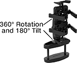
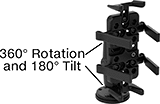
|  |
Clamp-On Pipe Mount Shown Installed |
Projection | For Device | Base | Attaching End | ||||||||||||||
|---|---|---|---|---|---|---|---|---|---|---|---|---|---|---|---|---|---|
Display Ht. | Clamping Distance Range | Min. | Max. | Wd. | Ht. | Dp. | Max. Load Cap., lb. | Material | Color | Lg. | Wd. | Range of Motion | Max. Tilt Range of Motion | Each | |||
Rotate, Tilt, Side to Side, Up and Down, In and Out | |||||||||||||||||
| 0" to 4 3/8" | 5/8" to 1 1/8" | 8 1/2" | 13 3/4" | 1 1/4" to 3 1/2" | 3 5/8" to 7 1/4" | 15/16" to 1 1/2" | 1 | Plastic | Black | 4 3/16" | 1 7/16" | 360° | 180° | 5943N11 | 0000000 | ||
 |  |
Magnetic Mount Shown Installed |
Projection | For Device | Attaching End | |||||||||||||
|---|---|---|---|---|---|---|---|---|---|---|---|---|---|---|---|
Display Ht. | Min. | Max. | Wd. | Ht. | Dp. | Max. Load Cap., lb. | Material | Color | Base Dia. | Range of Motion | Max. Tilt Range of Motion | Each | |||
Rotate, Tilt, Side to Side, Up and Down, In and Out | |||||||||||||||
| 0" to 1 3/4" | 5 1/8" | 8 1/16" | 1 1/4" to 3 1/2" | 3 5/8" to 7 1/4" | 15/16" to 1 1/2" | 1 | Plastic | Black | 2 1/2" | 360° | 180° | 5943N13 | 0000000 | ||
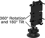
| 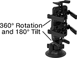 |
Suction Mount Shown Installed |
Projection | For Device | Attaching End | |||||||||||||
|---|---|---|---|---|---|---|---|---|---|---|---|---|---|---|---|
Display Ht. | Min. | Max. | Wd. | Ht. | Dp. | Max. Load Cap., lb. | Material | Color | Base Dia. | Range of Motion | Max. Tilt Range of Motion | Each | |||
Rotate, Tilt, Side to Side, Up and Down, In and Out | |||||||||||||||
| 0" to 6 5/8" | 6 7/16" | 9 5/16" | 1 1/4" to 3 1/2" | 3 5/8" to 7 1/4" | 15/16" to 1 1/2" | 1 | Plastic | Black | 3 5/16" | 360° | 180° | 5943N14 | 000000 | ||
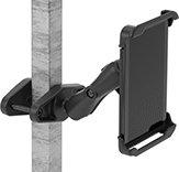
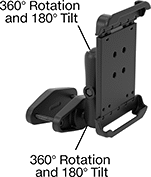
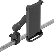
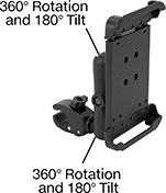
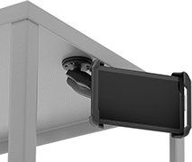
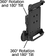
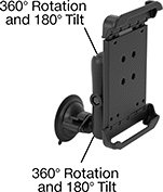
Tablet Mounts
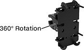
 |  |
Shown Installed |
Projection | Base | Attaching End | |||||||||||||
|---|---|---|---|---|---|---|---|---|---|---|---|---|---|---|---|
For Diag. Screen Size | Display Ht. | Clamping Distance Range | Min. | Max. | Max. Load Cap., lb. | Material | Color | Lg. | Wd. | Range of Motion | Max. Tilt Range of Motion | Each | |||
Rotate, Tilt, Side to Side, Up and Down, In and Out | |||||||||||||||
| 7" to 8" | 0" to 6 9/16" | 0" to 4" | 2 11/16" | 9 3/16" | 3 | Plastic | Black | 5 5/16" | 2 1/2" | 360° | 180° | 3796T201 | 0000000 | ||
| 9" to 10.5" | 0" to 6 9/16" | 0" to 4" | 2 13/16" | 9 3/8" | 3 | Plastic | Black | 5 5/16" | 2 1/2" | 360° | 180° | 3796T205 | 000000 | ||
 |  |
Shown Installed |
Projection | Base | Attaching End | |||||||||||||
|---|---|---|---|---|---|---|---|---|---|---|---|---|---|---|---|
For Diag. Screen Size | Display Ht. | Clamping Distance Range | Min. | Max. | Max. Load Cap., lb. | Material | Color | Lg. | Wd. | Range of Motion | Max. Tilt Range of Motion | Each | |||
Rotate, Tilt, Side to Side, Up and Down, In and Out | |||||||||||||||
| 7" to 8" | 0" to 8 1/16" | 5/8" to 1 1/8" | 2 11/16" | 10 11/16" | 3 | Plastic | Black | 4 7/8" | 1 7/16" | 360° | 180° | 3796T202 | 0000000 | ||
| 9" to 10.5" | 0" to 8 1/16" | 5/8" to 1 1/8" | 2 13/16" | 10 7/8" | 3 | Plastic | Black | 4 7/8" | 1 7/16" | 360° | 180° | 3796T206 | 000000 | ||
 |  |
Shown Installed |
Projection | Attaching End | ||||||||||||
|---|---|---|---|---|---|---|---|---|---|---|---|---|---|
For Diag. Screen Size | Display Ht. | Min. | Max. | Max. Load Cap., lb. | Material | Color | Base Dia. | Range of Motion | Max. Tilt Range of Motion | Each | |||
Rotate, Tilt, Side to Side, Up and Down, In and Out | |||||||||||||
| 7" to 8" | 0" to 6 7/8" | 2 11/16" | 9 1/2" | 3 | Plastic | Black | 2 1/2" | 360° | 180° | 3796T209 | 0000000 | ||
| 9" to 10.5" | 0" to 6 7/8" | 2 13/16" | 9 11/16" | 3 | Plastic | Black | 2 1/2" | 360° | 180° | 3796T211 | 000000 | ||
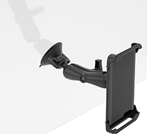 |  |
Shown Installed |
Projection | Attaching End | ||||||||||||
|---|---|---|---|---|---|---|---|---|---|---|---|---|---|
For Diag. Screen Size | Display Ht. | Min. | Max. | Max. Load Cap., lb. | Material | Color | Base Dia. | Range of Motion | Max. Tilt Range of Motion | Each | |||
Rotate, Tilt, Side to Side, Up and Down, In and Out | |||||||||||||
| 7" to 8" | 0" to 7 11/16" | 2 11/16" | 10 5/16" | 3 | Plastic | Black | 3 5/16" | 360° | 180° | 3796T203 | 000000 | ||
| 9" to 10.5" | 0" to 7 11/16" | 2 13/16" | 10 1/2" | 3 | Plastic | Black | 3 5/16" | 360° | 180° | 3796T207 | 000000 | ||
