


Filter by
Fitting Connection
For Use With
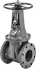
Body Material
Gate Material
End-to-End Length
Actuation
Overall Length
Maximum Pressure @ Temperature
Maximum Temperature
Thread Type
Shape
Overall Height
DFARS Specialty Metals
Stem Housing Connection
Fluid Handling
Facility and Grounds Maintenance
Safety Equipment