


Filter by
Outlet Pressure
Maximum Inlet Pressure
Maximum Temperature
Maximum Pressure
Set Pressure
Thread Type
Inlet Thread Type
Seal Material
Inlet Connection
Outlet Thread Type
Actuation
Export Control Classification Number (ECCN)
DFARS Specialty Metals
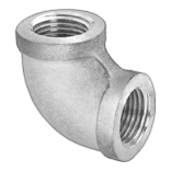
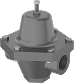
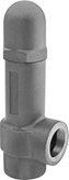
Vibration-Damping Pressure-Regulating Valves for Water, Oil, Air, and Inert Gas
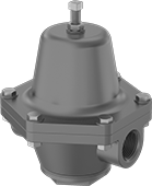 |
A cast iron body absorbs vibration from pressure changes to reduce wear and noise in your pipeline. These valves automatically reduce a high, variable inlet pressure to a lower, stable outlet pressure. Adjust the outlet pressure within the range.
Internal Strainer—Internal strainers trap debris.
Inlet | Outlet | ||||||||||||||||||||||||||||||||||||||||||||||||||||||||||||||||||||||||||||||||||||||||||||||||||
|---|---|---|---|---|---|---|---|---|---|---|---|---|---|---|---|---|---|---|---|---|---|---|---|---|---|---|---|---|---|---|---|---|---|---|---|---|---|---|---|---|---|---|---|---|---|---|---|---|---|---|---|---|---|---|---|---|---|---|---|---|---|---|---|---|---|---|---|---|---|---|---|---|---|---|---|---|---|---|---|---|---|---|---|---|---|---|---|---|---|---|---|---|---|---|---|---|---|---|---|
Pipe Size | Location | Max. Pressure, psi | Pipe Size | Location | Pressure Adjustment Method | End-to-End Lg. | For Use With | Temp. Range, ° F | Choose an Outlet Pressure, psi | Each | |||||||||||||||||||||||||||||||||||||||||||||||||||||||||||||||||||||||||||||||||||||||||
NPT Female | |||||||||||||||||||||||||||||||||||||||||||||||||||||||||||||||||||||||||||||||||||||||||||||||||||
Cast Iron Body—Buna-N Diaphragm and Seal with Internal Strainer | |||||||||||||||||||||||||||||||||||||||||||||||||||||||||||||||||||||||||||||||||||||||||||||||||||
| 1/4 | Side | 200 | 1/4 | Side | Screw | 3" | Water, Oil, Air, Inert Gas | 32 to 180 | 2 to 25 , 20 to 60 | 4674K41 | 0000000 | ||||||||||||||||||||||||||||||||||||||||||||||||||||||||||||||||||||||||||||||||||||||||
| 3/8 | Side | 200 | 3/8 | Side | Screw | 3 7/8" | Water, Oil, Air, Inert Gas | 32 to 180 | 2 to 30 , 20 to 70 , 40 to 110 , 90 to 150 | 4674K42 | 000000 | ||||||||||||||||||||||||||||||||||||||||||||||||||||||||||||||||||||||||||||||||||||||||
| 1/2 | Side | 200 | 1/2 | Side | Screw | 4 1/2" | Water, Oil, Air, Inert Gas | 32 to 180 | 2 to 30 , 10 to 50 , 30 to 125 , 50 to 125 | 4674K43 | 000000 | ||||||||||||||||||||||||||||||||||||||||||||||||||||||||||||||||||||||||||||||||||||||||
| 3/4 | Side | 200 | 3/4 | Side | Screw | 5 1/8" | Water, Oil, Air, Inert Gas | 32 to 180 | 2 to 20 , 10 to 35 , 30 to 75 , 50 to 110 , 105 to 125 | 4674K44 | 000000 | ||||||||||||||||||||||||||||||||||||||||||||||||||||||||||||||||||||||||||||||||||||||||
| 1 | Side | 200 | 1 | Side | Screw | 5 7/8" | Water, Oil, Air, Inert Gas | 32 to 180 | 2 to 20 , 10 to 45 , 20 to 60 , 55 to 100 , 90 to 125 | 4674K45 | 000000 | ||||||||||||||||||||||||||||||||||||||||||||||||||||||||||||||||||||||||||||||||||||||||
| 1 1/4 | Side | 200 | 1 1/4 | Side | Screw | 6 3/4" | Water, Oil, Air, Inert Gas | 32 to 180 | 2 to 15 , 10 to 30 , 20 to 50 , 45 to 100 , 90 to 150 | 4674K46 | 000000 | ||||||||||||||||||||||||||||||||||||||||||||||||||||||||||||||||||||||||||||||||||||||||
| 1 1/2 | Side | 200 | 1 1/2 | Side | Screw | 6 3/4" | Water, Oil, Air, Inert Gas | 32 to 180 | 2 to 15 , 10 to 30 , 20 to 50 , 45 to 100 , 90 to 125 | 4674K47 | 000000 | ||||||||||||||||||||||||||||||||||||||||||||||||||||||||||||||||||||||||||||||||||||||||
| 2 | Side | 200 | 2 | Side | Screw | 9 1/4" | Water, Oil, Air, Inert Gas | 32 to 180 | 2 to 20 , 10 to 60 , 20 to 100 , 90 to 125 | 4674K48 | 00000000 | ||||||||||||||||||||||||||||||||||||||||||||||||||||||||||||||||||||||||||||||||||||||||
Cast Iron Body—Fluoroelastomer Diaphragm and 420 Stainless Steel Seal | |||||||||||||||||||||||||||||||||||||||||||||||||||||||||||||||||||||||||||||||||||||||||||||||||||
| 3/8 | Side | 250 | 3/8 | Side | Screw | 4 1/4" | Water, Oil, Air, Inert Gas | 32 to 300 | 0 to 10 , 10 to 50 , 40 to 100 , 100 to 200 | 9796K11 | 000000 | ||||||||||||||||||||||||||||||||||||||||||||||||||||||||||||||||||||||||||||||||||||||||
| 1/2 | Side | 250 | 1/2 | Side | Screw | 3 5/8" | Water, Oil, Air, Inert Gas | 32 to 300 | 0 to 10 , 10 to 50 , 40 to 100 , 100 to 200 | 9796K12 | 000000 | ||||||||||||||||||||||||||||||||||||||||||||||||||||||||||||||||||||||||||||||||||||||||
| 3/4 | Side | 250 | 3/4 | Side | Screw | 3 5/8" | Water, Oil, Air, Inert Gas | 32 to 300 | 0 to 10 , 10 to 50 , 40 to 100 , 100 to 200 | 9796K13 | 000000 | ||||||||||||||||||||||||||||||||||||||||||||||||||||||||||||||||||||||||||||||||||||||||
| 1 | Side | 250 | 1 | Side | Screw | 4 1/2" | Water, Oil, Air, Inert Gas | 32 to 300 | 0 to 10 , 10 to 30 , 30 to 50 , 40 to 85 | 9796K14 | 000000 | ||||||||||||||||||||||||||||||||||||||||||||||||||||||||||||||||||||||||||||||||||||||||
| 2 | Side | 250 | 2 | Side | Screw | 6 1/2" | Water, Oil, Air, Inert Gas | 32 to 300 | 0 to 10 , 10 to 30 , 30 to 50 , 40 to 85 | 9796K15 | 000000 | ||||||||||||||||||||||||||||||||||||||||||||||||||||||||||||||||||||||||||||||||||||||||
Pressure-Regulating Valves for Steam
 |
Automatically reduce a high, variable inlet pressure in your steam system to a lower, stable outlet pressure. Adjust the outlet pressure within the range. These valves have a cast iron body that absorbs vibration from pressure changes to reduce wear and noise in your pipeline.
Internal Strainer—Internal strainers trap debris.
Valves | Repair Kits | ||||||||||||||||||||||||||||||||||||||||||||||||||||||||||||||||||||||||||||||||||||||||||||||||||
|---|---|---|---|---|---|---|---|---|---|---|---|---|---|---|---|---|---|---|---|---|---|---|---|---|---|---|---|---|---|---|---|---|---|---|---|---|---|---|---|---|---|---|---|---|---|---|---|---|---|---|---|---|---|---|---|---|---|---|---|---|---|---|---|---|---|---|---|---|---|---|---|---|---|---|---|---|---|---|---|---|---|---|---|---|---|---|---|---|---|---|---|---|---|---|---|---|---|---|---|
Inlet | Outlet | ||||||||||||||||||||||||||||||||||||||||||||||||||||||||||||||||||||||||||||||||||||||||||||||||||
Pipe Size | Location | Max. Pressure, psi | Pipe Size | Location | Pressure Adjustment Method | End-to-End Lg. | For Use With | Temp. Range, ° F | Choose an Outlet Pressure, psi | Each | Each | ||||||||||||||||||||||||||||||||||||||||||||||||||||||||||||||||||||||||||||||||||||||||
NPT Female | |||||||||||||||||||||||||||||||||||||||||||||||||||||||||||||||||||||||||||||||||||||||||||||||||||
Cast Iron Body—Bronze Diaphragm and 420 Stainless Steel Seal | |||||||||||||||||||||||||||||||||||||||||||||||||||||||||||||||||||||||||||||||||||||||||||||||||||
| 1/2 | Side | 250 | 1/2 | Side | Screw | 3 5/8" | Steam | -20 to 400 | 0 to 10 , 10 to 50 , 40 to 100 , 100 to 200 | 9796K38 | 0000000 | 9796K96 | 000000 | ||||||||||||||||||||||||||||||||||||||||||||||||||||||||||||||||||||||||||||||||||||||
| 3/4 | Side | 250 | 3/4 | Side | Screw | 3 5/8" | Steam | -20 to 400 | 0 to 10 , 10 to 50 , 40 to 100 , 100 to 200 | 9796K39 | 000000 | 9796K96 | 00000 | ||||||||||||||||||||||||||||||||||||||||||||||||||||||||||||||||||||||||||||||||||||||
| 1 | Side | 250 | 1 | Side | Screw | 4 1/2" | Steam | -20 to 400 | 0 to 10 , 10 to 30 , 30 to 50 , 40 to 85 | 9796K91 | 000000 | 9796K97 | 000000 | ||||||||||||||||||||||||||||||||||||||||||||||||||||||||||||||||||||||||||||||||||||||
| 1 1/4 | Side | 250 | 1 1/4 | Side | Screw | 4 1/2" | Steam | -20 to 400 | 0 to 10 , 10 to 30 , 30 to 50 , 40 to 85 | 9796K92 | 000000 | 9796K97 | 000000 | ||||||||||||||||||||||||||||||||||||||||||||||||||||||||||||||||||||||||||||||||||||||
| 1 1/2 | Side | 250 | 1 1/2 | Side | Screw | 6 1/2" | Steam | -20 to 400 | 0 to 10 , 10 to 30 , 30 to 50 , 40 to 85 | 9796K93 | 000000 | 9796K99 | 000000 | ||||||||||||||||||||||||||||||||||||||||||||||||||||||||||||||||||||||||||||||||||||||
| 2 | Side | 250 | 2 | Side | Screw | 6 1/2" | Steam | -20 to 400 | 0 to 10 , 10 to 30 , 30 to 50 , 40 to 85 | 9796K94 | 000000 | 9796K99 | 000000 | ||||||||||||||||||||||||||||||||||||||||||||||||||||||||||||||||||||||||||||||||||||||
Cast Iron Body—Bronze Diaphragm and PTFE Seal with Internal Strainer | |||||||||||||||||||||||||||||||||||||||||||||||||||||||||||||||||||||||||||||||||||||||||||||||||||
| 1/4 | Side | 150 | 1/4 | Side | Screw | 3" | Steam | -20 to 400 | 2 to 25 , 20 to 60 , 30 to 100 | 4674K61 | 000000 | ——— | 0 | ||||||||||||||||||||||||||||||||||||||||||||||||||||||||||||||||||||||||||||||||||||||
| 3/8 | Side | 150 | 3/8 | Side | Screw | 3 7/8" | Steam | -20 to 400 | 2 to 30 , 20 to 70 , 90 to 150 | 4674K62 | 000000 | ——— | 0 | ||||||||||||||||||||||||||||||||||||||||||||||||||||||||||||||||||||||||||||||||||||||
| 1/2 | Side | 150 | 1/2 | Side | Screw | 4 1/2" | Steam | -20 to 400 | 2 to 30 , 10 to 50 , 30 to 125 , 50 to 150 | 4674K63 | 000000 | 4674K91 | 000000 | ||||||||||||||||||||||||||||||||||||||||||||||||||||||||||||||||||||||||||||||||||||||
| 3/4 | Side | 150 | 3/4 | Side | Screw | 5 1/8" | Steam | -20 to 400 | 2 to 20 , 10 to 35 , 30 to 75 , 50 to 110 , 105 to 150 | 4674K64 | 000000 | 4674K92 | 000000 | ||||||||||||||||||||||||||||||||||||||||||||||||||||||||||||||||||||||||||||||||||||||
| 1 | Side | 150 | 1 | Side | Screw | 5 7/8" | Steam | -20 to 400 | 2 to 20 , 10 to 45 , 20 to 60 , 55 to 100 , 90 to 150 | 4674K65 | 000000 | 4674K93 | 000000 | ||||||||||||||||||||||||||||||||||||||||||||||||||||||||||||||||||||||||||||||||||||||
| 1 1/4 | Side | 150 | 1 1/4 | Side | Screw | 6 3/4" | Steam | -20 to 400 | 2 to 15 , 10 to 30 , 20 to 50 , 45 to 100 , 90 to 150 | 4674K66 | 000000 | 4674K94 | 000000 | ||||||||||||||||||||||||||||||||||||||||||||||||||||||||||||||||||||||||||||||||||||||
| 1 1/2 | Side | 150 | 1 1/2 | Side | Screw | 6 3/4" | Steam | -20 to 400 | 2 to 15 , 10 to 30 , 20 to 50 , 45 to 100 , 90 to 150 | 4674K67 | 000000 | 4674K94 | 000000 | ||||||||||||||||||||||||||||||||||||||||||||||||||||||||||||||||||||||||||||||||||||||
| 2 | Side | 150 | 2 | Side | Screw | 9 1/4" | Steam | -20 to 400 | 2 to 20 , 10 to 60 , 20 to 100 , 90 to 150 | 4674K68 | 00000000 | 4674K95 | 000000 | ||||||||||||||||||||||||||||||||||||||||||||||||||||||||||||||||||||||||||||||||||||||
Pressure-Regulating Inline Hydraulic Valves
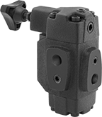 |
When input pressure varies, use these valves to maintain a consistent pressure. They are often placed after a directional-control valve and before an actuator, such as a cylinder. They have an indicator/gauge port for the inlet and one for the outlet so you can monitor that output pressure remains steady.
Inlet/Outlet Connection | Relief Connection | Overall | |||||||||||||||||||||||||||||||||||||||||||||||||||||||||||||||||||||||||||||||||||||||||||||||||
|---|---|---|---|---|---|---|---|---|---|---|---|---|---|---|---|---|---|---|---|---|---|---|---|---|---|---|---|---|---|---|---|---|---|---|---|---|---|---|---|---|---|---|---|---|---|---|---|---|---|---|---|---|---|---|---|---|---|---|---|---|---|---|---|---|---|---|---|---|---|---|---|---|---|---|---|---|---|---|---|---|---|---|---|---|---|---|---|---|---|---|---|---|---|---|---|---|---|---|---|
Pipe Size | Dash Size | Pipe Size | Dash Size | Max. Flow Rate, gpm | Max. Pressure, psi | Lg. | Wd. | Ht. | For Use With | Choose a Set Pressure, psi | Each | ||||||||||||||||||||||||||||||||||||||||||||||||||||||||||||||||||||||||||||||||||||||||
NPT Female Inlet and Relief Port | |||||||||||||||||||||||||||||||||||||||||||||||||||||||||||||||||||||||||||||||||||||||||||||||||||
Cast Iron Body—Buna-N Seal | |||||||||||||||||||||||||||||||||||||||||||||||||||||||||||||||||||||||||||||||||||||||||||||||||||
| 3/4 | 12 | 1/4 | 04 | 33 | 3,000 | 5 7/8" | 3 3/4" | 7 1/8" | Hydraulic Fluid | 100 to 1,000 , 500 to 2,000 , 1,000 to 3,000 | 9474T2 | 0000000 | |||||||||||||||||||||||||||||||||||||||||||||||||||||||||||||||||||||||||||||||||||||||
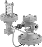
Back-Pressure-Regulating Valves for Water and Oil
 |
Commonly used as bypass lines after centrifugal, reciprocating, and rotary pumps, these valves obstruct flow to maintain sufficient operating pressure in your system. If the system pressure exceeds the set pressure, they exhaust through the threaded relief port. Adjust the set pressure within the range. Valves have a cast iron body that absorbs vibration from pressure changes to reduce wear and noise in your pipeline.
Inlet | Outlet | Relief Port | |||||||||||||||||||||||||||||||||||||||||||||||||||||||||||||||||||||||||||||||||||||||||||||||||
|---|---|---|---|---|---|---|---|---|---|---|---|---|---|---|---|---|---|---|---|---|---|---|---|---|---|---|---|---|---|---|---|---|---|---|---|---|---|---|---|---|---|---|---|---|---|---|---|---|---|---|---|---|---|---|---|---|---|---|---|---|---|---|---|---|---|---|---|---|---|---|---|---|---|---|---|---|---|---|---|---|---|---|---|---|---|---|---|---|---|---|---|---|---|---|---|---|---|---|---|
Pipe Size | Location | Max. Pressure, psi | Pipe Size | Location | Pressure Adjustment Method | Pipe Size | Location | End-to-End Lg. | For Use With | Temp. Range, ° F | Choose an Outlet Pressure, psi | Each | |||||||||||||||||||||||||||||||||||||||||||||||||||||||||||||||||||||||||||||||||||||||
NPT Female | |||||||||||||||||||||||||||||||||||||||||||||||||||||||||||||||||||||||||||||||||||||||||||||||||||
Cast Iron Body—Nickel Diaphragm and 303 Stainless Steel Seal | |||||||||||||||||||||||||||||||||||||||||||||||||||||||||||||||||||||||||||||||||||||||||||||||||||
| 1/2 | Side | 400 | 1/2 | Side | Screw | 1/2 | Bottom | 2 7/8" | Water, Oil | -40 to 200 | 0 to 25 , 5 to 50 , 30 to 100 , 75 to 175 , 150 to 400 | 4675K21 | 000000000 | ||||||||||||||||||||||||||||||||||||||||||||||||||||||||||||||||||||||||||||||||||||||
| 1 1/4 | Side | 400 | 1 1/4 | Side | Screw | 1 1/4 | Bottom | 4 1/4" | Water, Oil | -40 to 200 | 20 to 85 , 40 to 125 , 50 to 230 , 175 to 380 , 300 to 400 | 4675K25 | 00000000 | ||||||||||||||||||||||||||||||||||||||||||||||||||||||||||||||||||||||||||||||||||||||
| 1 1/2 | Side | 400 | 1 1/2 | Side | Screw | 1 1/2 | Bottom | 5" | Water, Oil | -40 to 200 | 10 to 55 , 30 to 100 , 40 to 200 , 125 to 300 , 200 to 400 | 4675K26 | 00000000 | ||||||||||||||||||||||||||||||||||||||||||||||||||||||||||||||||||||||||||||||||||||||
| 2 | Side | 400 | 2 | Side | Screw | 2 | Bottom | 5" | Water, Oil | -40 to 200 | 10 to 55 , 30 to 100 , 40 to 200 , 125 to 300 , 200 to 400 | 4675K27 | 00000000 | ||||||||||||||||||||||||||||||||||||||||||||||||||||||||||||||||||||||||||||||||||||||
High-Accuracy Pressure-Regulating Valves for Steam
 |
Control steam line pressure with ±1 psi accuracy. These valves automatically reduce a high, variable inlet pressure to a lower, stable outlet pressure. Adjust the outlet pressure within the range. Valves have a cast iron body that absorbs vibration from pressure changes to reduce wear and noise in your pipeline. They meet ANSI/FCI 70-2 Class IV for tight shut-off (max. leakage rate of 0.01%). Install 1/4 NPT male pipe (not included) between the control valve and your downstream steam line.
Repair Kits—Repair kits (sold separately) include replacement seals, diaphragm, spring, and spring assembly.
Valves | Repair Kits | ||||||||||||||||||||||||||||||||||||||||||||||||||||||||||||||||||||||||||||||||||||||||||||||||||
|---|---|---|---|---|---|---|---|---|---|---|---|---|---|---|---|---|---|---|---|---|---|---|---|---|---|---|---|---|---|---|---|---|---|---|---|---|---|---|---|---|---|---|---|---|---|---|---|---|---|---|---|---|---|---|---|---|---|---|---|---|---|---|---|---|---|---|---|---|---|---|---|---|---|---|---|---|---|---|---|---|---|---|---|---|---|---|---|---|---|---|---|---|---|---|---|---|---|---|---|
Inlet | Outlet | ||||||||||||||||||||||||||||||||||||||||||||||||||||||||||||||||||||||||||||||||||||||||||||||||||
Pipe Size | Location | Max. Pressure, psi | Pipe Size | Location | Pressure Adjustment Method | For Use With | Temp. Range, ° F | Specs. Met | Choose an Outlet Pressure, psi | Each | Each | ||||||||||||||||||||||||||||||||||||||||||||||||||||||||||||||||||||||||||||||||||||||||
NPT Female | |||||||||||||||||||||||||||||||||||||||||||||||||||||||||||||||||||||||||||||||||||||||||||||||||||
Cast Iron Body—301 Stainless Steel Diaphragm and 420 Stainless Steel Seal | |||||||||||||||||||||||||||||||||||||||||||||||||||||||||||||||||||||||||||||||||||||||||||||||||||
| 1/2 | Side | 250 | 1/2 | Side | Screw | Steam | 40 to 450 | ANSI/FCI 70-2 Class IV | 3 to 20 , 5 to 50 , 10 to 100 , 20 to 150 | 9792K19 | 000000000 | 9792K32 | 0000000 | ||||||||||||||||||||||||||||||||||||||||||||||||||||||||||||||||||||||||||||||||||||||
| 3/4 | Side | 250 | 3/4 | Side | Screw | Steam | 40 to 450 | ANSI/FCI 70-2 Class IV | 3 to 20 , 5 to 50 , 10 to 100 , 20 to 150 | 9792K21 | 00000000 | 9792K33 | 000000 | ||||||||||||||||||||||||||||||||||||||||||||||||||||||||||||||||||||||||||||||||||||||
| 1 | Side | 250 | 1 | Side | Screw | Steam | 40 to 450 | ANSI/FCI 70-2 Class IV | 3 to 20 , 5 to 50 , 10 to 100 , 20 to 150 | 9792K23 | 00000000 | 9792K34 | 000000 | ||||||||||||||||||||||||||||||||||||||||||||||||||||||||||||||||||||||||||||||||||||||
| 1 1/4 | Side | 250 | 1 1/4 | Side | Screw | Steam | 40 to 450 | ANSI/FCI 70-2 Class IV | 3 to 20 , 5 to 50 , 10 to 100 , 20 to 150 | 9792K25 | 00000000 | 9792K35 | 000000 | ||||||||||||||||||||||||||||||||||||||||||||||||||||||||||||||||||||||||||||||||||||||
| 1 1/2 | Side | 250 | 1 1/2 | Side | Screw | Steam | 40 to 450 | ANSI/FCI 70-2 Class IV | 3 to 20 , 5 to 50 , 10 to 100 , 20 to 150 | 9792K27 | 00000000 | 9792K36 | 000000 | ||||||||||||||||||||||||||||||||||||||||||||||||||||||||||||||||||||||||||||||||||||||
| 2 | Side | 250 | 2 | Side | Screw | Steam | 40 to 450 | ANSI/FCI 70-2 Class IV | 3 to 20 , 5 to 50 , 10 to 100 , 20 to 150 | 9792K29 | 00000000 | 9792K37 | 00000000 | ||||||||||||||||||||||||||||||||||||||||||||||||||||||||||||||||||||||||||||||||||||||
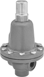
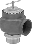
Hydraulic Pressure-Relief Valves
 |
Iron |
To set the pressure, unscrew the cap and turn the adjustment screw. Valves begin opening at the set pressure and fully open at about 10% over the set pressure. They begin closing as pressure drops and close when the system pressure is restored below the set pressure.
Iron Body—Iron valves absorb vibration to reduce noise and wear in the pipeline.
Inlet Connection | Relief Connection | Overall | |||||||||||||||||||||||||||||||||||||||||||||||||||||||||||||||||||||||||||||||||||||||||||||||||
|---|---|---|---|---|---|---|---|---|---|---|---|---|---|---|---|---|---|---|---|---|---|---|---|---|---|---|---|---|---|---|---|---|---|---|---|---|---|---|---|---|---|---|---|---|---|---|---|---|---|---|---|---|---|---|---|---|---|---|---|---|---|---|---|---|---|---|---|---|---|---|---|---|---|---|---|---|---|---|---|---|---|---|---|---|---|---|---|---|---|---|---|---|---|---|---|---|---|---|---|
Pipe Size | Dash Size | Pipe Size | Dash Size | Lg. | Wd. | Ht. | Temp. Range, ° F | Choose a Set Pressure, psi | Each | ||||||||||||||||||||||||||||||||||||||||||||||||||||||||||||||||||||||||||||||||||||||||||
NPT Female Inlet and NPT Female Relief Port | |||||||||||||||||||||||||||||||||||||||||||||||||||||||||||||||||||||||||||||||||||||||||||||||||||
Iron Body | |||||||||||||||||||||||||||||||||||||||||||||||||||||||||||||||||||||||||||||||||||||||||||||||||||
| 3/8 | 06 | 3/8 | 06 | 2 1/16" | 1 3/8" | 5 3/8" | -20 to 400 | 3 to 10 , 7 to 35 , 30 to 100 , 60 to 175 , 150 to 350 , 300 to 500 | 4704K32 | 0000000 | |||||||||||||||||||||||||||||||||||||||||||||||||||||||||||||||||||||||||||||||||||||||||
| 1/2 | 08 | 1/2 | 08 | 2 3/16" | 1 7/16" | 6 3/16" | -20 to 400 | 3 to 10 , 7 to 35 , 30 to 100 , 60 to 175 , 150 to 350 , 300 to 500 | 4704K11 | 000000 | |||||||||||||||||||||||||||||||||||||||||||||||||||||||||||||||||||||||||||||||||||||||||
| 3/4 | 12 | 3/4 | 12 | 2 11/16" | 1 11/16" | 6 15/16" | -20 to 400 | 3 to 10 , 7 to 35 , 30 to 100 , 60 to 175 , 150 to 350 , 300 to 500 | 4704K12 | 000000 | |||||||||||||||||||||||||||||||||||||||||||||||||||||||||||||||||||||||||||||||||||||||||
| 1 | 16 | 1 | 16 | 3 5/16" | 2 1/16" | 8 1/4" | -20 to 400 | 3 to 10 , 7 to 35 , 30 to 100 , 60 to 175 , 150 to 350 , 300 to 500 | 4704K13 | 000000 | |||||||||||||||||||||||||||||||||||||||||||||||||||||||||||||||||||||||||||||||||||||||||
| 1 1/4 | 20 | 1 1/4 | 20 | 3 13/16" | 2 1/2" | 9 9/16" | -20 to 400 | 3 to 10 , 7 to 35 , 30 to 100 , 60 to 175 , 150 to 350 , 300 to 500 | 4704K14 | 000000 | |||||||||||||||||||||||||||||||||||||||||||||||||||||||||||||||||||||||||||||||||||||||||
| 1 1/2 | 24 | 1 1/2 | 24 | 4 1/8" | 2 7/8" | 11 1/16" | -20 to 400 | 3 to 10 , 7 to 35 , 30 to 100 , 60 to 175 , 150 to 350 , 300 to 500 | 4704K25 | 000000 | |||||||||||||||||||||||||||||||||||||||||||||||||||||||||||||||||||||||||||||||||||||||||
| 2 | 32 | 2 | 32 | 4 5/8" | 3 1/4" | 13" | -20 to 400 | 3 to 10 , 7 to 35 , 30 to 100 , 60 to 175 , 150 to 350 , 250 to 600 | 4704K26 | 000000 | |||||||||||||||||||||||||||||||||||||||||||||||||||||||||||||||||||||||||||||||||||||||||
Large-Diameter Remote-Discharge Fast-Acting Pressure-Relief Valves for Air and Inert Gas
NPT Male Inlet and NPT Female Relief Port
 |
Inlet | Relief | ||||||||||||||||||||||||||||||||||||||||||||||||||||||||||||||||||||||||||||||||||||||||||||||||||
|---|---|---|---|---|---|---|---|---|---|---|---|---|---|---|---|---|---|---|---|---|---|---|---|---|---|---|---|---|---|---|---|---|---|---|---|---|---|---|---|---|---|---|---|---|---|---|---|---|---|---|---|---|---|---|---|---|---|---|---|---|---|---|---|---|---|---|---|---|---|---|---|---|---|---|---|---|---|---|---|---|---|---|---|---|---|---|---|---|---|---|---|---|---|---|---|---|---|---|---|
Pipe Size | Location | Max. Pressure, psi | Port Pipe Size | Port Location | Shape | Overall Ht. | For Use With | Temp. Range, ° F | Test Mechanism | Valve Type | Choose a Set Pressure, psi | Each | |||||||||||||||||||||||||||||||||||||||||||||||||||||||||||||||||||||||||||||||||||||||
Cast Iron Body—Bronze Seal | |||||||||||||||||||||||||||||||||||||||||||||||||||||||||||||||||||||||||||||||||||||||||||||||||||
| 2 | Bottom | 60 | 2 | Side | 90° Elbow | 7" | Air, Inert Gas | -20 to 406 | T-Handle | Pop Safety | 2 , 4 , 6 , 8 , 10 , 12 , 14 | 8175K31 | 0000000 | ||||||||||||||||||||||||||||||||||||||||||||||||||||||||||||||||||||||||||||||||||||||
| 2 1/2 | Bottom | 60 | 2 1/2 | Side | 90° Elbow | 8" | Air, Inert Gas | -20 to 406 | T-Handle | Pop Safety | 2 , 4 , 6 , 8 , 10 , 12 , 14 | 8175K33 | 000000 | ||||||||||||||||||||||||||||||||||||||||||||||||||||||||||||||||||||||||||||||||||||||
| 3 | Bottom | 60 | 3 | Side | 90° Elbow | 9" | Air, Inert Gas | -20 to 406 | T-Handle | Pop Safety | 2 , 4 , 6 , 8 , 10 , 12 , 14 | 8175K35 | 00000000 | ||||||||||||||||||||||||||||||||||||||||||||||||||||||||||||||||||||||||||||||||||||||
Large-Diameter Remote-Discharge ASME-Code Fast-Acting Pressure-Relief Valves for Air and Inert Gas
NPT Male Inlet and NPT Female Relief Port
|
Inlet | Relief | ||||||||||||||||||||||||||||||||||||||||||||||||||||||||||||||||||||||||||||||||||||||||||||||||||
|---|---|---|---|---|---|---|---|---|---|---|---|---|---|---|---|---|---|---|---|---|---|---|---|---|---|---|---|---|---|---|---|---|---|---|---|---|---|---|---|---|---|---|---|---|---|---|---|---|---|---|---|---|---|---|---|---|---|---|---|---|---|---|---|---|---|---|---|---|---|---|---|---|---|---|---|---|---|---|---|---|---|---|---|---|---|---|---|---|---|---|---|---|---|---|---|---|---|---|---|
Pipe Size | Location | Max. Pressure, psi | Port Pipe Size | Port Location | Shape | Overall Ht. | For Use With | Temp. Range, ° F | Test Mechanism | Valve Type | Certification | Choose a Set Pressure, psi | Each | ||||||||||||||||||||||||||||||||||||||||||||||||||||||||||||||||||||||||||||||||||||||
Cast Iron Body—Bronze Seal | |||||||||||||||||||||||||||||||||||||||||||||||||||||||||||||||||||||||||||||||||||||||||||||||||||
| 2 | Bottom | 60 | 2 | Side | 90° Elbow | 7" | Air, Inert Gas | -20 to 406 | T-Handle | Pop Safety | ASME BPVC.VIII | 16 , 18 , 20 , 22 , 24 , 26 , 28 , 30 , 32 , 34 , 36 , 38 , 40 , 42 , 44 , 46 , 48 , 50 , 52 , 54 , 56 , 58 , 60 | 8175K32 | 0000000 | |||||||||||||||||||||||||||||||||||||||||||||||||||||||||||||||||||||||||||||||||||||
| 2 1/2 | Bottom | 60 | 2 1/2 | Side | 90° Elbow | 8" | Air, Inert Gas | -20 to 406 | T-Handle | Pop Safety | ASME BPVC.VIII | 16 , 18 , 20 , 22 , 24 , 26 , 28 , 30 , 32 , 34 , 36 , 38 , 40 , 42 , 44 , 46 , 48 , 50 , 52 , 54 , 56 , 58 , 60 | 8175K34 | 000000 | |||||||||||||||||||||||||||||||||||||||||||||||||||||||||||||||||||||||||||||||||||||
| 3 | Bottom | 60 | 3 | Side | 90° Elbow | 9" | Air, Inert Gas | -20 to 406 | T-Handle | Pop Safety | ASME BPVC.VIII | 16 , 18 , 20 , 22 , 24 , 26 , 28 , 30 , 32 , 34 , 36 , 38 , 40 , 42 , 44 , 46 , 48 , 50 , 52 , 54 , 56 , 58 , 60 | 8175K36 | 00000000 | |||||||||||||||||||||||||||||||||||||||||||||||||||||||||||||||||||||||||||||||||||||
