


Filter by
Electrical Connection
Mounting Location
Electrical Protection Type
Certification
U.S.–Mexico–Canada Agreement (USMCA) Qualifying
DFARS Specialty Metals
Export Control Classification Number (ECCN)
Wire Connection


Switch Starting Position
Surface-Mount GFCIs
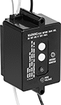 |
Mount and hardwire these GFCIs to your equipment to provide ground fault protection. They will trip if a ground fault is detected; press the button to reset. In case of a power outage, the reset is automatic.
Electrical Connection | ||||||||||||||
|---|---|---|---|---|---|---|---|---|---|---|---|---|---|---|
Voltage, V AC | Current, amp | Input | Output | Ht. | Wd. | Dp. | Features | No. of Mounting Holes | Mounting Hole Dia. | Mounting Fasteners Included | Certification | Each | ||
| 120 | 20 | Wire Leads | Wire Leads | 3.8" | 2.3" | 2.2" | Reset Button, Test Button, Power-Indicating Light | 2 | 3/16" | No | UL Recognized Component | 72155K73 | 000000 | |
Extension Cord GFCI Converters
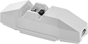 |
Inline GFCI |
Hardwire one of these converters to an extension cord to keep personnel safe from electric shock.
Automatic Reset—Converters with automatic GFCI reset immediately regain power after ground is established.
Manual Reset—Converters with manual GFCI reset prevent unexpected start-up.
For Cable OD | Reset Type | No. of Outlets | AWG | Current, amp | Voltage, V AC | Material | Certification | Color | Each | ||||||||||||||||||||||||||||||||||||||||||||||||||||||||||||||||||||||||||||||||||||||||||
|---|---|---|---|---|---|---|---|---|---|---|---|---|---|---|---|---|---|---|---|---|---|---|---|---|---|---|---|---|---|---|---|---|---|---|---|---|---|---|---|---|---|---|---|---|---|---|---|---|---|---|---|---|---|---|---|---|---|---|---|---|---|---|---|---|---|---|---|---|---|---|---|---|---|---|---|---|---|---|---|---|---|---|---|---|---|---|---|---|---|---|---|---|---|---|---|---|---|---|---|
Inline GFCI | |||||||||||||||||||||||||||||||||||||||||||||||||||||||||||||||||||||||||||||||||||||||||||||||||||
| 5/16" to 7/16" | Manual | — | — | 20 | 125 | Polycarbonate | UL Listed, CSA Certified | Yellow | 7228K12 | 000000 | |||||||||||||||||||||||||||||||||||||||||||||||||||||||||||||||||||||||||||||||||||||||||
| 5/16" to 7/16" | Manual | — | — | 20 | 240 | Polycarbonate | UL Listed | Yellow | 7228K23 | 000000 | |||||||||||||||||||||||||||||||||||||||||||||||||||||||||||||||||||||||||||||||||||||||||
| 5/16" to 9/16" | Automatic | — | — | 20 | 120 | Polycarbonate | UL Listed, C-UL Listed | Black | 7228K19 | 00000 | |||||||||||||||||||||||||||||||||||||||||||||||||||||||||||||||||||||||||||||||||||||||||
Inline GFCI with NEMA 5-15 | |||||||||||||||||||||||||||||||||||||||||||||||||||||||||||||||||||||||||||||||||||||||||||||||||||
| 5/16" to 5/8" | Manual | 3 | 12 | 15 | 125 | Polycarbonate | UL Listed, C-UL Listed | Yellow | 7228K18 | 00000 | |||||||||||||||||||||||||||||||||||||||||||||||||||||||||||||||||||||||||||||||||||||||||
90° Elbow Plug GFCI with NEMA 5-15 | |||||||||||||||||||||||||||||||||||||||||||||||||||||||||||||||||||||||||||||||||||||||||||||||||||
| 5/16" to 7/16" | Manual | — | — | 15 | 125 | Polycarbonate | UL Listed, CSA Certified | Yellow | 7228K11 | 00000 | |||||||||||||||||||||||||||||||||||||||||||||||||||||||||||||||||||||||||||||||||||||||||
| 5/16" to 5/8" | Automatic | — | — | 15 | 125 | Polycarbonate | UL Listed, C-UL Listed | Black | 7228K15 | 00000 | |||||||||||||||||||||||||||||||||||||||||||||||||||||||||||||||||||||||||||||||||||||||||
Straight Inline GFCI with NEMA 5-15 | |||||||||||||||||||||||||||||||||||||||||||||||||||||||||||||||||||||||||||||||||||||||||||||||||||
| 5/16" to 5/8" | Automatic | — | 12 | 15 | 125 | Polycarbonate | UL Listed, C-UL Listed | Yellow | 7228K16 | 00000 | |||||||||||||||||||||||||||||||||||||||||||||||||||||||||||||||||||||||||||||||||||||||||
| 5/16" to 5/8" | Manual | — | 12 | 15 | 125 | Polycarbonate | UL Listed, C-UL Listed | Yellow | 7228K17 | 00000 | |||||||||||||||||||||||||||||||||||||||||||||||||||||||||||||||||||||||||||||||||||||||||
Voltage-Monitoring Relays
Monitoring Relays
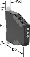 |
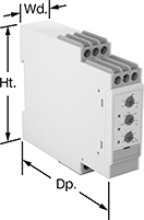
With Spring-Clamp Terminals—Relays with spring-clamp terminals connect and disconnect to wire without screws. Because there’s no screw, these connections are less likely to loosen over time, even in high-vibration environments.
Knob Adjustment—Relays with knob adjustments have knobs right on the front where you can set your trip voltage. You can see that they're wired correctly and when they're actuated based on the LED indicators. If you want to mount these relays to a surface instead of DIN rail, they have mounting holes.
No. of Terminals | Input Voltage | Trip Voltage Setting | Trip Time, sec. | Reset Type | Switching Current @ Voltage | Max. Switching Voltage | Adjustment Mechanism | Ht. | Wd. | Dp. | Features | Each | |||||||||||||||||||||||||||||||||||||||||||||||||||||||||||||||||||||||||||||||||||||||
|---|---|---|---|---|---|---|---|---|---|---|---|---|---|---|---|---|---|---|---|---|---|---|---|---|---|---|---|---|---|---|---|---|---|---|---|---|---|---|---|---|---|---|---|---|---|---|---|---|---|---|---|---|---|---|---|---|---|---|---|---|---|---|---|---|---|---|---|---|---|---|---|---|---|---|---|---|---|---|---|---|---|---|---|---|---|---|---|---|---|---|---|---|---|---|---|---|---|---|---|
1 Circuit Controlled with 1 Off or 1 On—SPDT | |||||||||||||||||||||||||||||||||||||||||||||||||||||||||||||||||||||||||||||||||||||||||||||||||||
With Spring-Clamp Terminals | |||||||||||||||||||||||||||||||||||||||||||||||||||||||||||||||||||||||||||||||||||||||||||||||||||
| 9 | 24V AC, 24V DC | 1V AC to 10V AC 3V AC to 30V AC 15V AC to 150V AC 1V DC to 10V DC 3V DC to 30V DC 15V DC to 150V DC | 0.1 to 30 | Automatic, Manual | 5 amp @ 240V AC 5 amp @ 30V DC | 250V AC 48V DC | Knob | 3.5" | 0.7" | 3.5" | LED Indicator | 8446N101 | 0000000 | ||||||||||||||||||||||||||||||||||||||||||||||||||||||||||||||||||||||||||||||||||||||
| 9 | 24V AC, 24V DC | 20V AC to 200V AC 30V AC to 300V AC 60V AC to 600V AC 20V DC to 200V DC 30V DC to 300V DC 60V DC to 600V DC | 0.1 to 30 | Automatic, Manual | 5 amp @ 240V AC 5 amp @ 30V DC | 250V AC 48V DC | Knob | 3.5" | 0.7" | 3.5" | LED Indicator | 8446N103 | 000000 | ||||||||||||||||||||||||||||||||||||||||||||||||||||||||||||||||||||||||||||||||||||||
| 9 | 120V AC, 240V AC | 1V AC to 10V AC 3V AC to 30V AC 15V AC to 150V AC 1V DC to 10V DC 3V DC to 30V DC 15V DC to 150V DC | 0.1 to 30 | Automatic, Manual | 5 amp @ 240V AC 5 amp @ 30V DC | 250V AC 48V DC | Knob | 3.5" | 0.7" | 3.5" | LED Indicator | 8446N102 | 000000 | ||||||||||||||||||||||||||||||||||||||||||||||||||||||||||||||||||||||||||||||||||||||
| 9 | 120V AC, 240V AC | 20V AC to 200V AC 30V AC to 300V AC 60V AC to 600V AC 20V DC to 200V DC 30V DC to 300V DC 60V DC to 600V DC | 0.1 to 30 | Automatic, Manual | 5 amp @ 240V AC 5 amp @ 30V DC | 250V AC 48V DC | Knob | 3.5" | 0.7" | 3.5" | LED Indicator | 8446N104 | 000000 | ||||||||||||||||||||||||||||||||||||||||||||||||||||||||||||||||||||||||||||||||||||||
Monitoring Relays with IO Link
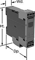 |
Relays with IO link can be programmed, monitored and reset remotely by connecting them to a programmable logic controller (PLC), human-machine interface (HMI), or computer. If you want to program them locally, they have a keypad.
With Spring-Clamp Terminals—Relays with spring-clamp terminals connect and disconnect to wire without screws. Because there’s no screw, these connections are less likely to loosen over time, even in high-vibration environments.
No. of Terminals | Input Voltage, V DC | Trip Voltage | Trip Time, sec. | Reset Type | Switching Current @ Voltage | Max. Switching Voltage | Adjustment Mechanism | Ht. | Wd. | Dp. | Digital Display Type | Features | Each | ||||||||||||||||||||||||||||||||||||||||||||||||||||||||||||||||||||||||||||||||||||||
|---|---|---|---|---|---|---|---|---|---|---|---|---|---|---|---|---|---|---|---|---|---|---|---|---|---|---|---|---|---|---|---|---|---|---|---|---|---|---|---|---|---|---|---|---|---|---|---|---|---|---|---|---|---|---|---|---|---|---|---|---|---|---|---|---|---|---|---|---|---|---|---|---|---|---|---|---|---|---|---|---|---|---|---|---|---|---|---|---|---|---|---|---|---|---|---|---|---|---|---|
1 Circuit Controlled with 1 Off or 1 On—SPDT | |||||||||||||||||||||||||||||||||||||||||||||||||||||||||||||||||||||||||||||||||||||||||||||||||||
With Screw Terminals | |||||||||||||||||||||||||||||||||||||||||||||||||||||||||||||||||||||||||||||||||||||||||||||||||||
| 9 | 24 | 10V AC to 600V AC, 10V DC to 600V DC | 0 to 999 | Automatic | 3 amp @ 240V AC 1 amp @ 24V DC | 400V AC 250V DC | External Controller, Keypad | 3.6" | 0.9" | 3.6" | LCD | Remote Reset | 8446N105 | 0000000 | |||||||||||||||||||||||||||||||||||||||||||||||||||||||||||||||||||||||||||||||||||||
With Spring-Clamp Terminals | |||||||||||||||||||||||||||||||||||||||||||||||||||||||||||||||||||||||||||||||||||||||||||||||||||
| 9 | 24 | 10V AC to 600V AC, 10V DC to 600V DC | 0 to 999 | Automatic | 3 amp @ 240V AC 1 amp @ 24V DC | 400V AC 250V DC | External Controller, Keypad | 3.8" | 0.9" | 3.6" | LCD | Remote Reset | 8446N106 | 000000 | |||||||||||||||||||||||||||||||||||||||||||||||||||||||||||||||||||||||||||||||||||||
Extension Cord ELCI Converters
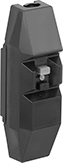 |
Prevent shocks from extension cords connected to boats, RVs, and other large electrical systems. These ELCI (equipment leakage circuit interrupters) converters monitor the flow of current to and from an electrical system. If they detect an imbalance, they cut off the power. They’re similar to GFCI converters, but they monitor an entire system rather than one device. They also tolerate a higher level of imbalance before they trip. These converters have a manual reset to keep equipment from starting unexpectedly.
For Cable OD | Reset Type | Current, amp | Voltage, V AC | Material | Certification | Color | Each | ||||||||||||||||||||||||||||||||||||||||||||||||||||||||||||||||||||||||||||||||||||||||||||
|---|---|---|---|---|---|---|---|---|---|---|---|---|---|---|---|---|---|---|---|---|---|---|---|---|---|---|---|---|---|---|---|---|---|---|---|---|---|---|---|---|---|---|---|---|---|---|---|---|---|---|---|---|---|---|---|---|---|---|---|---|---|---|---|---|---|---|---|---|---|---|---|---|---|---|---|---|---|---|---|---|---|---|---|---|---|---|---|---|---|---|---|---|---|---|---|---|---|---|---|
Inline ELCI | |||||||||||||||||||||||||||||||||||||||||||||||||||||||||||||||||||||||||||||||||||||||||||||||||||
| 5/16" to 7/16" | Manual | 20 | 120/240 | Polycarbonate | UL Listed, CSA Certified | Black | 5491N11 | 000000 | |||||||||||||||||||||||||||||||||||||||||||||||||||||||||||||||||||||||||||||||||||||||||||
Smart Multifunction Monitoring Relays
 |
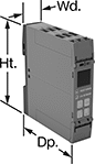
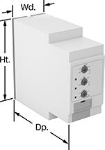
Remotely control these relays through an app on your smartphone—they simultaneously monitor phase, voltage, and frequency. The downloadable app lets you change the tripping range, modify settings, and save programs to apply to multiple relays. Tap your smartphone or tablet to the relays to connect to them. They use NFC (near field communication), so you don’t need to manually pair them like Bluetooth devices.
You’ll often see these relays used to protect motors, generators, and other three-phase circuits from burning out or overheating. They'll switch the circuit off if they detect voltage or frequencies outside of the set range or phase loss, imbalance, or reversal. You can see that they're wired correctly and when they're actuated based on the LED indicators. Rated IP20, they have recessed terminals that keep fingers and other objects from touching live circuits. Mount them on a 35 mm DIN rail (also known as DIN 3 rail) for fast installation.
No. of Terminals | Input Voltage, V AC | Trip Voltage, V AC | Input Freq., Hz | Trip Freq., Hz | Trip Time, sec. | Reset Type | Switching Current @ Voltage | Max. Switching Voltage, V AC | Ht. | Wd. | Dp. | Operating System Compatibility | Each | ||||||||||||||||||||||||||||||||||||||||||||||||||||||||||||||||||||||||||||||||||||||
|---|---|---|---|---|---|---|---|---|---|---|---|---|---|---|---|---|---|---|---|---|---|---|---|---|---|---|---|---|---|---|---|---|---|---|---|---|---|---|---|---|---|---|---|---|---|---|---|---|---|---|---|---|---|---|---|---|---|---|---|---|---|---|---|---|---|---|---|---|---|---|---|---|---|---|---|---|---|---|---|---|---|---|---|---|---|---|---|---|---|---|---|---|---|---|---|---|---|---|---|
2 Circuits Controlled with 2 Off or 2 On—DPDT | |||||||||||||||||||||||||||||||||||||||||||||||||||||||||||||||||||||||||||||||||||||||||||||||||||
With Screw Terminals | |||||||||||||||||||||||||||||||||||||||||||||||||||||||||||||||||||||||||||||||||||||||||||||||||||
| 12 | 208, 240, 300, 480 | 208 to 480 | 50, 60 | 45 to 66 | 0.1 to 60 | Automatic | 8 amp @ 240V AC | 250 | 3.5" | 0.9" | 3.9" | Android 7.0 or Later, iOS 14.5 or Later | 8452N11 | 0000000 | |||||||||||||||||||||||||||||||||||||||||||||||||||||||||||||||||||||||||||||||||||||
Multifunction Monitoring Relays
 |
Monitor phase, voltage, and frequency at the same time to protect motors, generators, and other three-phase circuits from burning out or overheating. They'll switch the circuit off if they detect voltage or frequencies outside of the set range or phase loss, imbalance, or reversal. Rated IP20, they have recessed terminals that keep fingers and other objects from touching live circuits. Mount them on a 35 mm DIN rail (also known as DIN 3 rail) for fast installation.
These relays use IO Link, so they can be programmed, monitored, and reset remotely by connecting them to a programmable logic controller (PLC), human-machine interface (HMI), or computer. If you want to program them locally, they have a keypad.
Spring-Clamp-Terminal Wire Connection—Relays with spring-clamp terminals connect and disconnect to wire without screws. Because there’s no screw, these connections are less likely to loosen over time, even in high-vibration environments.
No. of Terminals | Input Voltage, V DC | Trip Voltage, V AC | Input Freq., Hz | Trip Freq., Hz | Trip Time, sec. | Reset Type | Switching Current @ Voltage | Max. Switching Voltage | Adjustment Mechanism | Ht. | Wd. | Dp. | Each | ||||||||||||||||||||||||||||||||||||||||||||||||||||||||||||||||||||||||||||||||||||||
|---|---|---|---|---|---|---|---|---|---|---|---|---|---|---|---|---|---|---|---|---|---|---|---|---|---|---|---|---|---|---|---|---|---|---|---|---|---|---|---|---|---|---|---|---|---|---|---|---|---|---|---|---|---|---|---|---|---|---|---|---|---|---|---|---|---|---|---|---|---|---|---|---|---|---|---|---|---|---|---|---|---|---|---|---|---|---|---|---|---|---|---|---|---|---|---|---|---|---|---|
1 Circuit Controlled with 1 Off or 1 On—SPDT | |||||||||||||||||||||||||||||||||||||||||||||||||||||||||||||||||||||||||||||||||||||||||||||||||||
Screw Terminals with IO Link | |||||||||||||||||||||||||||||||||||||||||||||||||||||||||||||||||||||||||||||||||||||||||||||||||||
| 12 | 24 | 90 to 760 | 50, 60 | 15 to 70 | 0.1 to 30 | Automatic | 3 amp @ 240V AC 1 amp @ 24V DC | 400V AC 250V DC | External Controller, Keypad | 3.9" | 0.9" | 3.6" | 8449N12 | 0000000 | |||||||||||||||||||||||||||||||||||||||||||||||||||||||||||||||||||||||||||||||||||||
Spring-Clamp Terminals with IO Link | |||||||||||||||||||||||||||||||||||||||||||||||||||||||||||||||||||||||||||||||||||||||||||||||||||
| 12 | 24 | 90 to 760 | 50, 60 | 15 to 70 | 0.1 to 30 | Automatic | 3 amp @ 240V AC 1 amp @ 24V DC | 400V AC 250V DC | External Controller, Keypad | 3.9" | 0.9" | 3.6" | 8449N11 | 000000 | |||||||||||||||||||||||||||||||||||||||||||||||||||||||||||||||||||||||||||||||||||||
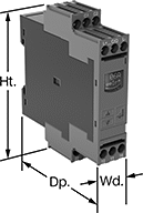
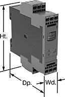
Frequency-Monitoring Relays
 |  |
DIN-Rail Mount | Relay-Socket Mount |
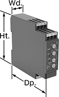
Prevent changes in frequency from damaging sensitive equipment. Often used with motors, fluorescent lighting, and controllers, these relays cut power to your device if the frequency falls outside the set range. Switches on the front of these relays let you set your trip frequency and time. You can see that they're wired correctly and when they're actuated based on the LED indicators. Rated IP20, these relays have recessed terminals that keep fingers and other objects from touching live circuits.
DIN-Rail Mount—DIN-rail mount relays snap onto 35 mm DIN rail (also known as DIN 3 rail) for fast installation.
Relay-Socket Mount—Relay-socket mount relays plug into a socket (sold separately), which is required for installation.
Monitoring Relays | Sockets | ||||||||||||||||||||||||||||||||||||||||||||||||||||||||||||||||||||||||||||||||||||||||||||||||||
|---|---|---|---|---|---|---|---|---|---|---|---|---|---|---|---|---|---|---|---|---|---|---|---|---|---|---|---|---|---|---|---|---|---|---|---|---|---|---|---|---|---|---|---|---|---|---|---|---|---|---|---|---|---|---|---|---|---|---|---|---|---|---|---|---|---|---|---|---|---|---|---|---|---|---|---|---|---|---|---|---|---|---|---|---|---|---|---|---|---|---|---|---|---|---|---|---|---|---|---|
Trip Frequency Setting, Hz | |||||||||||||||||||||||||||||||||||||||||||||||||||||||||||||||||||||||||||||||||||||||||||||||||||
No. of Terminals | Input Voltage, V AC | 50 Hz Input | 60 Hz Input | Trip Time, sec. | Reset Type | Switching Current @ Voltage | Max. Switching Voltage | Adjustment Mechanism | Ht. | Wd. | Dp. | Features | Each | Each | |||||||||||||||||||||||||||||||||||||||||||||||||||||||||||||||||||||||||||||||||||||
1 Circuit Controlled with 1 Off or 1 On—SPDT | |||||||||||||||||||||||||||||||||||||||||||||||||||||||||||||||||||||||||||||||||||||||||||||||||||
DIN-Rail Mount | |||||||||||||||||||||||||||||||||||||||||||||||||||||||||||||||||||||||||||||||||||||||||||||||||||
| 9 | 24, 48, 120, 240 | 40 to 60 48 to 52 | 50 to 70 58 to 62 | 0.1 to 30 | Automatic, Manual | 8 amp @ 240V AC 5 amp @ 24V DC | 250V AC 24V DC | DIP Switch | 3.1" | 0.9" | 3.9" | LED Indicator | 8477N11 | 0000000 | ——— | 0 | |||||||||||||||||||||||||||||||||||||||||||||||||||||||||||||||||||||||||||||||||||
Relay-Socket Mount | |||||||||||||||||||||||||||||||||||||||||||||||||||||||||||||||||||||||||||||||||||||||||||||||||||
| 1 | 24, 48, 120, 240 | 40 to 60 48 to 52 | 50 to 70 58 to 62 | 0.1 to 30 | Automatic, Manual | 8 amp @ 240V AC 5 amp @ 24V DC | 250V AC 24V DC | DIP Switch | 3.1" | 1.4" | 3.7" | LED Indicator | 8477N12 | 000000 | 7122K12 | 000000 | |||||||||||||||||||||||||||||||||||||||||||||||||||||||||||||||||||||||||||||||||||
Current-Monitoring Relays
 |  |  |
Screw Terminals Knob Adjustment | Screw Terminals with IO Link, Keypad Adjustment | Spring-Clamp Terminals with IO Link, Keypad Adjustment |
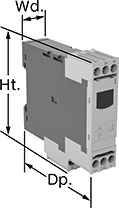
Protect electrical equipment from overcurrent and undercurrent damage—these relays continuously monitor current flow. When current is outside a set range, they trip and cut power to prevent overheating, fire hazards, and stalling. Rated IP20, these relays have recessed terminals that keep fingers and other objects from touching live circuits. Mount them on a 35 mm DIN rail (also known as DIN 3 rail) for fast installation.
Spring-Clamp-Terminal Wire Connection—Relays with spring-clamp terminals connect and disconnect to wire without screws. Because there’s no screw, these connections are less likely to loosen over time, even in high-vibration environments.
IO Link Communication Protocol—Relays with IO link can be programmed, monitored, and reset remotely by connecting them to a programmable logic controller (PLC), human-machine interface (HMI), or computer. If you want to program them locally, they have a keypad.
Knob Adjustment—Relays with knob adjustments have knobs right on the front where you can set your trip current. You can see that they're wired correctly and when they're actuated based on the LED indicators.
No. of Terminals | Input Voltage | Trip Current Setting, amp | Trip Current, amp | Trip Time, sec. | Reset Type | Switching Current @ Voltage | Max. Switching Voltage | Adjustment Mechanism | Ht. | Wd. | Dp. | Digital Display Type | Each | ||||||||||||||||||||||||||||||||||||||||||||||||||||||||||||||||||||||||||||||||||||||
|---|---|---|---|---|---|---|---|---|---|---|---|---|---|---|---|---|---|---|---|---|---|---|---|---|---|---|---|---|---|---|---|---|---|---|---|---|---|---|---|---|---|---|---|---|---|---|---|---|---|---|---|---|---|---|---|---|---|---|---|---|---|---|---|---|---|---|---|---|---|---|---|---|---|---|---|---|---|---|---|---|---|---|---|---|---|---|---|---|---|---|---|---|---|---|---|---|---|---|---|
Screw Terminals | |||||||||||||||||||||||||||||||||||||||||||||||||||||||||||||||||||||||||||||||||||||||||||||||||||
1 Circuit Controlled with 1 Off or 1 On—SPDT | |||||||||||||||||||||||||||||||||||||||||||||||||||||||||||||||||||||||||||||||||||||||||||||||||||
| 9 | 24V AC, 24V DC | 0.1 to 1, 0.5 to 5, 0.8 to 8 | — | 0.1 to 30 | Automatic, Manual | 5 amp @ 240V AC 5 amp @ 30V DC | 250V AC 30V DC | Knob | 3.5" | 0.9" | 3.9" | — | 8123N14 | 0000000 | |||||||||||||||||||||||||||||||||||||||||||||||||||||||||||||||||||||||||||||||||||||
| 9 | 120V AC, 240V AC | 0.1 to 1, 0.5 to 5, 0.8 to 8 | — | 0.1 to 30 | Automatic, Manual | 5 amp @ 240V AC 5 amp @ 30V DC | 250V AC 30V DC | Knob | 3.5" | 0.9" | 3.9" | — | 8123N13 | 000000 | |||||||||||||||||||||||||||||||||||||||||||||||||||||||||||||||||||||||||||||||||||||
Screw Terminals with IO Link | |||||||||||||||||||||||||||||||||||||||||||||||||||||||||||||||||||||||||||||||||||||||||||||||||||
1 Circuit Controlled with 1 Off or 1 On—SPDT | |||||||||||||||||||||||||||||||||||||||||||||||||||||||||||||||||||||||||||||||||||||||||||||||||||
| 9 | 24V DC | — | 0.05 to 10 | 0 to 999 | Automatic | 3 amp @ 240V AC 1 amp @ 24V DC | 400V AC 250V DC | External Controller, Keypad | 3.6" | 0.9" | 3.4" | LCD | 8123N11 | 000000 | |||||||||||||||||||||||||||||||||||||||||||||||||||||||||||||||||||||||||||||||||||||
Spring-Clamp Terminals with IO Link | |||||||||||||||||||||||||||||||||||||||||||||||||||||||||||||||||||||||||||||||||||||||||||||||||||
1 Circuit Controlled with 1 Off or 1 On—SPDT | |||||||||||||||||||||||||||||||||||||||||||||||||||||||||||||||||||||||||||||||||||||||||||||||||||
| 9 | 24V DC | — | 0.05 to 10 | 0 to 999 | Automatic | 3 amp @ 240V AC 1 amp @ 24V DC | 400V AC 250V DC | External Controller, Keypad | 3.8" | 0.9" | 3.4" | LCD | 8123N12 | 000000 | |||||||||||||||||||||||||||||||||||||||||||||||||||||||||||||||||||||||||||||||||||||
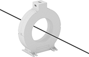
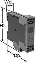
High-Current-Monitoring Relays
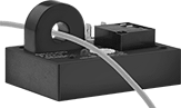 |
Prevent AC current overload in equipment such as motors and heaters.
These relays sense current flowing through wires routed through the opening. If the current exceeds a set trip point, the relay trips and starts the adjustable delay timer. After the timer's cycle, the relay cuts power to the equipment to protect against overload. Once current drops below the trip point, the relay allows power to flow again to the equipment.
To determine the current trip range for more than one wire, divide the listed trip range by the number of wires passed through the opening.
Current Trip for One Wire Range, amp | Switch Designation | Resistive Load Current @ AC Voltage | Delay Time Range, sec. | For Max. Wire Dia. | Ht. | Wd. | Dp. | Input AC Voltage, V AC | Wire Connection | Certification | Mount Type | Fasteners Included | Mounting Hole Dia. | No. of Mounting Holes | Each | ||||||||||||||||||||||||||||||||||||||||||||||||||||||||||||||||||||||||||||||||||||
|---|---|---|---|---|---|---|---|---|---|---|---|---|---|---|---|---|---|---|---|---|---|---|---|---|---|---|---|---|---|---|---|---|---|---|---|---|---|---|---|---|---|---|---|---|---|---|---|---|---|---|---|---|---|---|---|---|---|---|---|---|---|---|---|---|---|---|---|---|---|---|---|---|---|---|---|---|---|---|---|---|---|---|---|---|---|---|---|---|---|---|---|---|---|---|---|---|---|---|---|
Measures AC Current | |||||||||||||||||||||||||||||||||||||||||||||||||||||||||||||||||||||||||||||||||||||||||||||||||||
| 0.1 to 1 | SPDT | 10 amp @ 240V AC | 0.5 to 6 | 0.5" | 2.13" | 3.5" | 2.5" | 120 | Quick-Disconnect Terminal | UL Recognized Component | Screw On | No | 0.19" | 2 | 65795K69 | 0000000 | |||||||||||||||||||||||||||||||||||||||||||||||||||||||||||||||||||||||||||||||||||
| 1 to 10 | SPDT | 10 amp @ 240V AC | 0.5 to 6 | 0.5" | 2.13" | 3.5" | 2.5" | 120 | Quick-Disconnect Terminal | C-UL Recognized Component, UL Recognized Component | Screw On | No | 0.19" | 2 | 65795K71 | 000000 | |||||||||||||||||||||||||||||||||||||||||||||||||||||||||||||||||||||||||||||||||||
| 3 to 30 | SPDT | 10 amp @ 240V AC | 0.5 to 6 | 0.5" | 2.13" | 3.5" | 2.5" | 120 | Quick-Disconnect Terminal | C-UL Recognized Component, UL Recognized Component | Screw On | No | 0.19" | 2 | 65795K72 | 000000 | |||||||||||||||||||||||||||||||||||||||||||||||||||||||||||||||||||||||||||||||||||
| 6 to 60 | SPDT | 10 amp @ 240V AC | 0.5 to 6 | 0.5" | 2.13" | 3.5" | 2.5" | 120 | Quick-Disconnect Terminal | C-UL Recognized Component, UL Recognized Component | Screw On | No | 0.19" | 2 | 65795K73 | 000000 | |||||||||||||||||||||||||||||||||||||||||||||||||||||||||||||||||||||||||||||||||||
| 10 to 100 | SPDT | 10 amp @ 240V AC | 0.5 to 6 | 0.5" | 2.13" | 3.5" | 2.5" | 120 | Quick-Disconnect Terminal | C-UL Recognized Component, UL Recognized Component | Screw On | No | 0.19" | 2 | 65795K74 | 000000 | |||||||||||||||||||||||||||||||||||||||||||||||||||||||||||||||||||||||||||||||||||
Ground-Fault Monitoring Relays
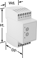 | 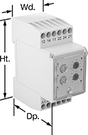 |
Screw Terminals | Screw Terminals Knob Adjustment |
 |  |
Screw Terminals with IO Link | Spring-Clamp Terminals with IO Link |
Detect and mitigate ground faults to prevent harm to equipment, circuits, and people. These relays monitor the differential between incoming and outgoing current, also known as residual current. When the balance is off, they trip and cut power to the circuit. These relays are highly sensitive, so you can trust them to de-energize faulty circuits before a minor issue becomes a major one. Rated IP20, they have recessed terminals that keep fingers and other objects from touching live circuits. Mount them on 35 mm DIN rail (also known as DIN 3 rail) for fast installation.
These relays require a current-indicating ring (sold separately) to operate. Choose a ring that is large enough for your lines to pass through. Feed the lines of the circuit through the center of the ring and connect the indicating ring output to the relay.
Spring-Clamp-Terminal Wire Connection—Relays with spring-clamp terminals connect and disconnect to wire without screws. Because they don’t have screws, there’s less of a risk that they will loosen over time, even when they’re under vibration.
IO Link Communication Protocol—Relays with IO link can be programmed, monitored, and reset remotely by connecting them to a programmable logic controller (PLC), human-machine interface (HMI), or computer. If you want to program them locally, they have a keypad.
Knob Adjustment—Relays with knob adjustments have knobs right on the front where you can set your trip current.
LED Indicator—Relays with an LED indicator show the status of your relay, so you know it is wired correctly and when it is actuated.
No. of Terminals | Input Voltage | Trip Current Setting, amp | Trip Current, amp | Trip Time, sec. | Switching Current @ Voltage | Max. Switching Voltage | Adjustment Mechanism | Ht. | Wd. | Dp. | Features | Each | |||||||||||||||||||||||||||||||||||||||||||||||||||||||||||||||||||||||||||||||||||||||
|---|---|---|---|---|---|---|---|---|---|---|---|---|---|---|---|---|---|---|---|---|---|---|---|---|---|---|---|---|---|---|---|---|---|---|---|---|---|---|---|---|---|---|---|---|---|---|---|---|---|---|---|---|---|---|---|---|---|---|---|---|---|---|---|---|---|---|---|---|---|---|---|---|---|---|---|---|---|---|---|---|---|---|---|---|---|---|---|---|---|---|---|---|---|---|---|---|---|---|---|
Screw Terminals | |||||||||||||||||||||||||||||||||||||||||||||||||||||||||||||||||||||||||||||||||||||||||||||||||||
2 Circuits Controlled with 2 Off or 2 On—DPDT | |||||||||||||||||||||||||||||||||||||||||||||||||||||||||||||||||||||||||||||||||||||||||||||||||||
| 12 | 24V AC, 48V AC, 120V AC, 240V AC | 0.03 | — | 0 | 5 amp @ 240V AC 5 amp @ 24V DC | 250V AC 24V DC | — | 3.2" | 1.4" | 2.6" | LED Indicator | 8121N101 | 0000000 | ||||||||||||||||||||||||||||||||||||||||||||||||||||||||||||||||||||||||||||||||||||||
| 12 | 24V AC, 48V AC, 120V AC, 240V AC | 0.3 | — | 0 | 5 amp @ 240V AC 5 amp @ 24V DC | 250V AC 24V DC | — | 3.2" | 1.4" | 2.6" | LED Indicator | 8121N102 | 000000 | ||||||||||||||||||||||||||||||||||||||||||||||||||||||||||||||||||||||||||||||||||||||
| 12 | 24V AC, 48V AC, 120V AC, 240V AC | — | 0.03 to 5 | 0 to 5 | 5 amp @ 240V AC 5 amp @ 24V DC | 250V AC 24V DC | Knob | 3.2" | 1.4" | 2.8" | LED Indicator | 8121N103 | 000000 | ||||||||||||||||||||||||||||||||||||||||||||||||||||||||||||||||||||||||||||||||||||||
| 12 | 24V AC, 48V AC, 120V AC, 240V AC | — | 0.3 to 30 | 0 to 5 | 5 amp @ 240V AC 5 amp @ 24V DC | 250V AC 24V DC | Knob | 3.2" | 1.4" | 2.8" | LED Indicator | 8121N104 | 000000 | ||||||||||||||||||||||||||||||||||||||||||||||||||||||||||||||||||||||||||||||||||||||
Screw Terminals with IO Link | |||||||||||||||||||||||||||||||||||||||||||||||||||||||||||||||||||||||||||||||||||||||||||||||||||
2 Circuits Controlled with 2 Off or 2 On—DPDT | |||||||||||||||||||||||||||||||||||||||||||||||||||||||||||||||||||||||||||||||||||||||||||||||||||
| 12 | 24V DC | — | 0.03 to 40 | 0 to 999 | 3 amp @ 240V AC 1 amp @ 24V DC | 400V AC 250V DC | External Controller, Keypad | 4" | 0.9" | 3.6" | Remote Reset | 8121N109 | 000000 | ||||||||||||||||||||||||||||||||||||||||||||||||||||||||||||||||||||||||||||||||||||||
Spring-Clamp Terminals with IO Link | |||||||||||||||||||||||||||||||||||||||||||||||||||||||||||||||||||||||||||||||||||||||||||||||||||
2 Circuits Controlled with 2 Off or 2 On—DPDT | |||||||||||||||||||||||||||||||||||||||||||||||||||||||||||||||||||||||||||||||||||||||||||||||||||
| 12 | 24V DC | — | 0.03 to 40 | 0 to 999 | 3 amp @ 240V AC 1 amp @ 24V DC | 400V AC 250V DC | External Controller, Keypad | 4.1" | 0.9" | 3.6" | Remote Reset | 8121N111 | 000000 | ||||||||||||||||||||||||||||||||||||||||||||||||||||||||||||||||||||||||||||||||||||||