


Filter by
For Hand Wheel Diameter

For Valve Control Type
For Use With
Message


Specifications Met
Export Control Classification Number (ECCN)
DFARS Specialty Metals
For Plug Width
Hinged Lockouts for Valve Hand Wheels
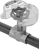 | 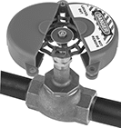 |
Clear Lockout Cover | Opaque Lockout Cover |
A hinged design makes mounting these lockouts easy. All prevent valve hand wheels from turning to keep you safe when repairing systems downstream. These lockouts help you comply with OSHA 29 CFR 1910.147 requirements for the control of hazardous energy.
Clear—Clear lockouts let you check the status of the equipment you’ve locked out at a glance. They’re a good choice for dial-indicating hand wheels.
Plastic—Plastic lockouts resist corrosion better than steel lockouts.
Powder-Coated Steel—Steel lockouts resist impact better than plastic lockouts.
For Hand Wheel Dia. | For Max. No. of Padlocks | For Max. Padlock Shackle Dia. | Temp. Range, ° F | For Valve Control Type | Includes | Label Included | Message | Specs. Met | Choose a Color | Each | |||
|---|---|---|---|---|---|---|---|---|---|---|---|---|---|
Clear Lockout Cover | |||||||||||||
Plastic | |||||||||||||
| 1" to 2 1/2" | 1 | 3/8" | -40 to 300 | Hand Wheel | 1 Each: English, Spanish, French Lockout Labels | Yes | Danger—Locked Out—Do Not Remove Peligro—Bloqueado—No Remueva Danger—Verrouillage—Ne Pas Enlever | OSHA Compliant 29 CFR 1910.147 | Clear | 47235K61 | 000000 | ||
| 2 1/2" to 5" | 1 | 3/8" | -40 to 300 | Hand Wheel | 1 Each: English, Spanish, French Lockout Labels | Yes | Danger—Locked Out—Do Not Remove Peligro—Bloqueado—No Remueva Danger—Verrouillage—Ne Pas Enlever | OSHA Compliant 29 CFR 1910.147 | Clear | 47235K62 | 00000 | ||
| 5" to 6 1/2" | 1 | 3/8" | -40 to 300 | Hand Wheel | 1 Each: English, Spanish, French Lockout Labels | Yes | Danger—Locked Out—Do Not Remove Peligro—Bloqueado—No Remueva Danger—Verrouillage—Ne Pas Enlever | OSHA Compliant 29 CFR 1910.147 | Clear | 47235K63 | 00000 | ||
| 6 1/2" to 10" | 1 | 3/8" | -40 to 300 | Hand Wheel | 1 Each: English, Spanish, French Lockout Labels | Yes | Danger—Locked Out—Do Not Remove Peligro—Bloqueado—No Remueva Danger—Verrouillage—Ne Pas Enlever | OSHA Compliant 29 CFR 1910.147 | Clear | 47235K64 | 00000 | ||
| 10" to 13" | 1 | 3/8" | -40 to 300 | Hand Wheel | 1 Each: English, Spanish, French Lockout Labels | Yes | Danger—Locked Out—Do Not Remove Peligro—Bloqueado—No Remueva Danger—Verrouillage—Ne Pas Enlever | OSHA Compliant 29 CFR 1910.147 | Clear | 47235K65 | 00000 | ||
Opaque Lockout Cover | |||||||||||||
Plastic | |||||||||||||
| 1" to 2 1/2" | 1 | 3/8" | -25 to 200 | Hand Wheel | 1 Each: English, Spanish, French Lockout Labels | Yes | Danger—Locked Out—Do Not Remove Peligro—Bloqueado—No Remueva Danger—Verrouillage—Ne Pas Enlever | OSHA Compliant 29 CFR 1910.147 | Blue, Green, Red, Yellow | 47235K51 | 00000 | ||
| 2 1/2" to 5" | 1 | 3/8" | -25 to 200 | Hand Wheel | 1 Each: English, Spanish, French Lockout Labels | Yes | Danger—Locked Out—Do Not Remove Peligro—Bloqueado—No Remueva Danger—Verrouillage—Ne Pas Enlever | OSHA Compliant 29 CFR 1910.147 | Blue, Green, Red, Yellow | 47235K52 | 00000 | ||
| 5" to 6 1/2" | 1 | 3/8" | -25 to 200 | Hand Wheel | 1 Each: English, Spanish, French Lockout Labels | Yes | Danger—Locked Out—Do Not Remove Peligro—Bloqueado—No Remueva Danger—Verrouillage—Ne Pas Enlever | OSHA Compliant 29 CFR 1910.147 | Blue, Green, Red, Yellow | 47235K53 | 00000 | ||
| 6 1/2" to 10" | 1 | 3/8" | -25 to 200 | Hand Wheel | 1 Each: English, Spanish, French Lockout Labels | Yes | Danger—Locked Out—Do Not Remove Peligro—Bloqueado—No Remueva Danger—Verrouillage—Ne Pas Enlever | OSHA Compliant 29 CFR 1910.147 | Blue, Green, Red, Yellow | 47235K54 | 00000 | ||
| 10" to 13" | 1 | 3/8" | -25 to 200 | Hand Wheel | 1 Each: English, Spanish, French Lockout Labels | Yes | Danger—Locked Out—Do Not Remove Peligro—Bloqueado—No Remueva Danger—Verrouillage—Ne Pas Enlever | OSHA Compliant 29 CFR 1910.147 | Blue, Green, Red, Yellow | 47235K55 | 00000 | ||
Powder-Coated Steel | |||||||||||||
| 1" to 2 1/2" | 2 | 5/16" | -100 to 400 | Hand Wheel | — | No | — | OSHA Compliant 29 CFR 1910.147 | Red | 6189N11 | 00000 | ||
| 2 1/2" to 5" | 3 | 5/16" | -100 to 400 | Hand Wheel | — | No | — | OSHA Compliant 29 CFR 1910.147 | Red | 6189N12 | 00000 | ||
| 5" to 6 1/2" | 4 | 5/16" | -100 to 400 | Hand Wheel | — | No | — | OSHA Compliant 29 CFR 1910.147 | Red | 6189N13 | 00000 | ||
| 6 1/2" to 10" | 4 | 5/16" | -100 to 400 | Hand Wheel | — | No | — | OSHA Compliant 29 CFR 1910.147 | Red | 6189N14 | 000000 | ||
| 10" to 13" | 4 | 5/16" | -100 to 400 | Hand Wheel | — | No | — | OSHA Compliant 29 CFR 1910.147 | Red | 6189N15 | 000000 | ||
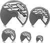
Nestable Lockouts for Valve Hand Wheels
 |
Each lockout rotates into itself, making installation in tight spaces easier than other lockouts. All prevent valve handles from turning and include write-on labels. They help you comply with OSHA 29 CFR 1910.147 procedures for the control of energy sources that could injure workers.
For Hand Wheel Dia. | For Max. No. of Padlocks | For Max. Padlock Shackle Dia. | Temp. Range, ° F | For Valve Control Type | Color | Label Included | Language | Message | Specs. Met | Each | |||
|---|---|---|---|---|---|---|---|---|---|---|---|---|---|
Lockout Cover | |||||||||||||
Plastic | |||||||||||||
| 1" to 3" | 2 | 9/32" | -50 to 350 | Hand Wheel | Red | Yes | English, Spanish, French | Danger—Do Not Operate, Peligro—No Usar, Danger—Ne Pas Utiliser | OSHA Compliant 29 CFR 1910.147 | 3286A11 | 000000 | ||
| 2" to 5" | 3 | 9/32" | -50 to 350 | Hand Wheel | Red | Yes | English, Spanish, French | Danger—Do Not Operate, Peligro—No Usar, Danger—Ne Pas Utiliser | OSHA Compliant 29 CFR 1910.147 | 3286A12 | 00000 | ||
| 4" to 6 1/2" | 4 | 9/32" | -50 to 350 | Hand Wheel | Red | Yes | English, Spanish, French | Danger—Do Not Operate, Peligro—No Usar, Danger—Ne Pas Utiliser | OSHA Compliant 29 CFR 1910.147 | 3286A13 | 00000 | ||
| 6" to 10" | 4 | 9/32" | -50 to 350 | Hand Wheel | Red | Yes | English, Spanish, French | Danger—Do Not Operate, Peligro—No Usar, Danger—Ne Pas Utiliser | OSHA Compliant 29 CFR 1910.147 | 3286A14 | 00000 | ||
| 8" to 13" | 4 | 9/32" | -50 to 350 | Hand Wheel | Red | Yes | English, Spanish, French | Danger—Do Not Operate, Peligro—No Usar, Danger—Ne Pas Utiliser | OSHA Compliant 29 CFR 1910.147 | 3286A15 | 00000 | ||
Electrical Plug Lockouts
 |
For Max. of 4 Padlocks (Padlock Not Included) |
 |
For Max. of 6 Padlocks (Padlock Not Included) |
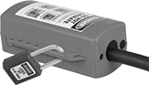
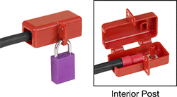
Lock out a plug that powers machinery so no one starts it up during maintenance. Place a plug into the cylinder of these lockouts and secure with a padlock. All can fit a standard electrical plug that has a single cord. Made of plastic, they resist corrosion and are nonconductive for use with electronics. These lockouts help you comply with OSHA 29 CFR 1910.147, which requires electrical circuits to be locked out to prevent injury.
For 4 Maximum Padlocks and For 6 Maximum Padlocks—Lockouts for 2 or more padlocks let multiple people add their own padlock. This keeps everyone safe until all of the maintenance work is done and all padlocks are removed.
2 Holes—Lockouts with 2 holes let you insert a cord from either end. That means you can lock out two devices at once, or lock out both the plug and socket of the same cord.
5 Holes—Lockouts with 5 holes have a variety of hole sizes to handle different cord diameters. They’ll fit dual-cord battery plugs for forklifts, as well as standard single-cord plugs. Use them with gas-powered equipment, too—the largest hole on these lockouts fits a gas cylinder valve.
UL ECVP 2809-2—Hasps that meet UL 2809-2 are made of 100% recycled materials and are sustainably sourced to meet purchasing requirements for LEED-certified facilities.
Message—Lockouts with a message alert passersby that a plug has been locked out for safety.
For Plug | Overall | |||||||||||||||
|---|---|---|---|---|---|---|---|---|---|---|---|---|---|---|---|---|
For Max. No. of Padlocks | For Max. Padlock Shackle Dia. | For Maximum Cord Diameter | No. of Holes | Max. Lg. | Wd. | Lg. | Wd. | Ht. | Dia. | Temp. Range, ° F | Message | Specs. Met | Each | |||
Yellow Plastic | ||||||||||||||||
| 4 | 3/8" | 1 1/8" | 2 | 4 3/4" | 1 1/2" to 2 3/4" | 7 1/4" | — | — | 4 1/4" | -20 to 140 | — | OSHA Compliant 29 CFR 1910.147 | 15515A41 | 000000 | ||
Red Plastic (English) | ||||||||||||||||
| 6 | 9/32" | 1 1/8", 1", 1" | 5 | 6 3/4" | 1/2" to 2 1/2" | 7 1/4" | 4 1/4" | 3" | — | -40 to 300 | Danger—Do Not Operate—Equipment Locked Out | OSHA Compliant 29 CFR 1910.147, UL ECVP 2809-2 | 15515A51 | 00000 | ||
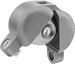
Valve Handle Lockouts
Style G
 |
Style G (Padlocks Not Included) |
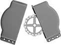
Hinged Cover—Hinged lockouts secure the valve handle in any position. They have a one-piece design that stays together for easy storage.
For Handle | ||||||||||||
|---|---|---|---|---|---|---|---|---|---|---|---|---|
Lg. | Thk. | Min. Padlock Vert. Shackle Clearance | For Max. No. of Padlocks | For Max. Padlock Shackle Dia. | Temp. Range, ° F | Color | Label Included | Specs. Met | Each | |||
Hinged—Locks in Closed and Open Position | ||||||||||||
Plastic | ||||||||||||
| 1/2" to 8" | 3/4" to 2" | 3/4" | 4 | 5/16" | -40 to 210 | Red | No | OSHA Compliant 29 CFR 1910.147 | 45075K71 | 000000 | ||
Two-Piece Lockouts for Valve Hand Wheels
 |
Prevent valve hand wheels from turning. These lockouts help you comply with OSHA 29 CFR 1910.147 procedures for the control of energy sources that could injure workers.
Wall-Mount Electrical and Valve Lockout Sets with Padlocks
 | 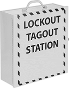 | 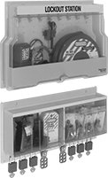 |
Cabinet | Cabinet (Shown Closed) | Case |
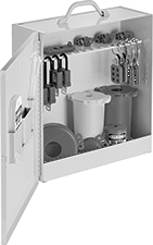
Keep everything you need to lock out most electrical equipment and valves around your facility in a single spot against the wall. These sets have supplies for locking out circuit breakers, valves, plugs, wall switches, and other controls. The supplies are red or yellow to alert people to maintenance. They help you comply with OSHA 29 CFR 1910.147, which requires power sources and supply lines to be locked out to prevent injuries.
Cabinet—Cabinets are made of stainless steel, so they resist damage better than our plastic cases. They meet UL 2809-2, so they’re made of at least 90% recycled materials to meet purchasing requirements for LEED-certified facilities.
Case—Cases have a clear plastic cover to protect lockout items against water and dust while still letting you see inside. They have a larger set of supplies than our cabinets, including a cable lockout for weaving through and around panel boxes, valve wheels, and other hard-to-secure equipment.
Mounting Holes | |||||||||||
|---|---|---|---|---|---|---|---|---|---|---|---|
Includes | Ht. | Wd. | Dp. | Fasteners Included | No. Of | Screw Size | Specs. Met | Each | |||
Cabinet | |||||||||||
| 1 Each: Gas Cylinder Lockout 1 Each: Wall Switch Lockout 2 Each: Plug Lockouts 2 Valve Wheel Lockouts (1 Each that fits 1"-2 1/2" and 2 1/2"-5" Diameter Wheels) 3 Each: Circuit Breaker Lockouts 4 Each: Lockout Hasps 4 Each: 1/4" Shackle Diameter Keyed Differently Padlocks with Labels 10 Each: Tags 10 Each: Cable Ties | 16" | 15 1/4" | 5 1/2" | No | 4 | No. 10 | OSHA Compliant 29 CFR 1910.147, UL ECVP 2809-2 | 4977A201 | 0000000 | ||
Case | |||||||||||
| 2 Each: Plug Lockouts 1 Each: Cable Lockout 1 Each: Snap-On Lockout Hasp 2 Each: Lockout Hasps 2 Each: Valve Handle Lockouts (Fits 3/8 to 4 Pipe Size) 2 Each: Wall Switch Lockouts 4 Valve Wheel Lockouts (1 Each that fits 1"-3", 2"-5", 4"-6 1/2", and 6"-10" Diameter Wheels) 6 Each: 1/4" Shackle Diameter Keyed Differently Padlocks with Labels 8 Each: Circuit Breaker Lockouts 24 Each: Tags 24 Each: Cable Ties | 27" | 23 1/2" | 4 1/2" | No | 8 | No. 10 | OSHA Compliant 29 CFR 1910.147 | 4977A15 | 000000 | ||
Keyed Alike Locking Door Handle Guards
 |
ID | OD | Inside Dp. | For Door Swing Direction | Material | Each | ||
|---|---|---|---|---|---|---|---|
| 2 3/8" | 2 7/8" | 1 7/8" | Left, Right | Gray Painted Aluminum | 12035A32 | 000000 |
Battery Cable Connector Lockouts
 |
Hinged Cover For 1 Battery Cable |
 |
Hinged Cover For 2 Battery Cables |
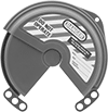
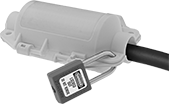
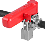
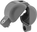
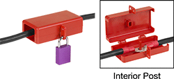
Padlock these lockouts over the ends of battery cables to keep forklifts, pallet jacks, and other machinery powered off during maintenance. They signal that equipment is being serviced, preventing accidental startups. These lockouts have space for two padlocks, so teams can safely perform two maintenance tasks at once.
Made from nonconductive plastic, they insulate battery terminals and protect workers from accidental shocks, helping you comply with OSHA 29 CFR 1910.147 requirements for the control of electricity. These lockouts are also rated UL 94 HB, which means they have been tested in a horizontal position for flame resistance; the slow-burning plastic keeps flames from spreading.
Hinged Cover—Hinged lockouts fully enclose battery cable ends and inline connections. Fit battery connectors, such as lugs and terminal clamps, over the internal post to hold cables in place.
For Max. Connector | Cable Opening | Overall | |||||||||||||||||
|---|---|---|---|---|---|---|---|---|---|---|---|---|---|---|---|---|---|---|---|
Lg. | Wd. | Ht. | For No. of Battery Cables | Wd. | Ht. | Post Dia. | Lg. | Wd. | Ht. | For Max. No. of Padlocks | For Max. Padlock Shackle Dia. | Temp. Range, ° F | Color | Specs. Met | Flammability Rating | Each | |||
Hinged Cover | |||||||||||||||||||
Plastic | |||||||||||||||||||
| 2 5/8" | 1 1/2" | 1 1/4" | 1 | 1" | 1" | 1/4" | 3 3/4" | 2 7/8" | 1 3/8" | 2 | 5/16" | -40 to 212 | Red | OSHA Compliant 29 CFR 1910.147 | UL 94 HB | 3699N11 | 000000 | ||
| 2 5/8" | 2 3/4" | 1 5/8" | 2 | 2" | 1 3/8" | 1/4" | 5 3/4" | 4 1/8" | 1 3/4" | 2 | 5/16" | -40 to 212 | Red | OSHA Compliant 29 CFR 1910.147 | UL 94 HB | 3699N12 | 00000 | ||
Electrical, Valve, and Air Hose Lockout Sets with Padlocks
 |
Lock out nearly any power source or supply line in your facility, from circuit breakers and valve handles to wall switches and air hose. These sets include padlocks, hasps, and other lockouts in a carrying case—just grab them and go. They also include a cable lockout for panel boxes, handwheels, and other devices that require extra length to secure. To alert others to maintenance and repair, the lockouts are red. The lockouts in these sets help you meet OSHA 29 CFR 1910.147 requirements to prevent injuries caused by accidental startups.
For Use With | For Valve Control Type | Includes | Specs. Met | Each | ||
|---|---|---|---|---|---|---|
| Air Hose, Circuit Breakers, Electrical Panels, Electrical Plugs, Push Buttons, Valves, Wall Switches | Hand Wheel, Handle | 1 Each: Wall Switch Lockout 2 Each: Plug Lockouts 2 Valve Wheel Lockouts (1 Each that fits 1"-2 1/2" and 2 1/2"-5" Diameter Wheels) 3 Each: Circuit Breaker Lockouts 1 Each: Cable Lockout 2 Each: Lockout Hasps 1 Each: Air Hose Lockout 1 Each: Push Button Lockout 1 Each: Valve Handle Lockout (Fits 3/8 to 1 Pipe Size) 2 Each: 1/4" Shackle Diameter Keyed Differently Padlocks with Labels 5 Each: Cable Ties 5 Each: Tags Carrying Case | OSHA Compliant 29 CFR 1910.147 | 6778N11 | 0000000 |
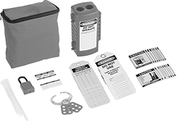
Electrical and Valve Lockout Sets with Padlocks
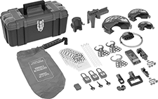 |
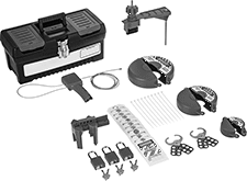
Everything you need to lock out your electrical equipment or valves. These sets are your one stop shop for padlocks, hasps, and other lockout devices. Bright red, they alert others to service or repairs. Use them to comply with OSHA 29 CFR 1910.147 requirements to prevent injuries caused by accidental startups during maintenance.
1 Each: Cable Lockout—Sets with a cable lockout can be used on panel boxes or handwheels. Thanks to their extra length, they weave between handles or wheels to prevent them from turning.
Plastic Box—Sets in a plastic box are more weather resistant than sets in a carrying case or fanny pack.
Fanny Pack—Sets in a fanny pack are strapped around your waist to keep lockout devices within reach.
Carrying Case—Sets in a carrying case store lockout components in a soft, portable bag.
UL ECVP 2809-2—Sets that meet UL 2809-2 are made of 100% recycled materials, so they meet purchasing requirements for LEED-certified facilities.
Lockout Type | Includes | Specs. Met | Each | ||
|---|---|---|---|---|---|
| Cover, Cable, Hasp, Bag | 1 Each: Wall Switch Lockout 1 Each: Cable Lockout 1 Each: Plug Lockout 5 Each: Circuit Breaker Lockouts Plastic Box 1 Each: Adjustable Ball Valve Lockout 1 Each: Plug Prong Lockout 3 Valve Wheel Lockouts (1 Each that fits 1"-3", 2"-5", and 4"-6 1/2" Diameter Wheels) 1 Each: Hoist Cover 3 Each: Lockout Hasps 3 Each: 1/4" Shackle Diameter Keyed Alike Padlocks with Labels 6 Each: Tags 6 Cable Ties | OSHA Compliant 29 CFR 1910.147 | 4974A14 | 0000000 | |
| Cover, Cable, Hasp, Bag | 1 Each: Wall Switch Lockout 2 Each: Plug Lockouts 1 Each: Cable Lockout 6 Each: 1/4" Shackle Diameter Keyed Differently Padlocks with Labels 12 Each: Tags 3 Valve Wheel Lockouts (1 Each that fits 1"-3", 2"-5", and 4"-6 1/2" Diameter Wheels) 11 Each: Circuit Breaker Lockouts 2 Each: Valve Lockouts 6 Each: Lockout Hasps 12 Cable Ties Carrying Case | OSHA Compliant 29 CFR 1910.147 | 4974A16 | 000000 | |
| Cover, Hasp | 4 Each: Lockout Hasps 2 Each: 1/4" Shackle Diameter Keyed Differently Padlocks with Labels 5 Each: Tags 1 Each: Plug Lockout 1 Each: Circuit Breaker Lockout 1 Valve Wheel Lockout (fits 2 1/2"-5" Diameter Wheels) 5 Cable Ties Fanny Pack | OSHA Compliant 29 CFR 1910.147, UL ECVP 2809-2 | 4974A212 | 000000 | |
| Cover, Hasp | 2 Each: Lockout Hasps 2 Each: 1/4" Shackle Diameter Keyed Differently Padlocks with Labels 2 Each: Tags 1 Each: Circuit Breaker Lockout 2 Valve Wheel Lockouts (1 Each that fits 1"-2 1/2" and 2 1/2"-4" Diameter Wheels) 3 Cable Ties Carrying Case | OSHA Compliant 29 CFR 1910.147, UL ECVP 2809-2 | 4974A211 | 000000 |
Gas Cylinder Lockouts
Plastic
 |
A (Padlock Not Included) |
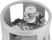
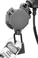
Plastic lockouts are more corrosion resistant and lighter in weight than steel lockouts. However, they aren’t as strong. These lockouts have a warning label to alert passersby.
Style A—Style A are for forklift gas cylinder handwheels. With holes for up to three padlocks, each person can add their own as they start a job. Each padlock adds another layer of security, and until the last is removed, these lockouts won’t open. Made of 100% recycled materials, they meet UL 2809-2 purchasing requirements for LEED-certified facilities.
Style | For Hand Wheel Dia. Range | For Max. No. of Padlocks | For Max. Padlock Shackle Dia. | Overall Lg. | Max. Temp., ° F | Color | Message | Specs. Met | Each | |||
|---|---|---|---|---|---|---|---|---|---|---|---|---|
| A | 1 1/4" to 2 3/16" | 3 | 5/16" | 3 1/2" | 200 | Yellow | Danger—Do Not Operate—Equipment Locked Out | OSHA Compliant 29 CFR 1910.147, UL ECVP 2809-2 | 3409A115 | 000000 | ||
Keyed Differently Locking Door Handle Guards
|
ID | OD | Inside Dp. | For Door Swing Direction | Material | Each | ||
|---|---|---|---|---|---|---|---|
| 2 3/8" | 2 7/8" | 1 7/8" | Left, Right | Gray Painted Aluminum | 12035A31 | 000000 |
Nestable Lockout Sets for Valve Hand Wheels
 |
Each lockout rotates into itself, making installation in tight spaces easier than other lockouts. The lockouts are red. They help you comply with OSHA 29 CFR 1910.147 procedures for the control of energy sources that could injure workers.
For Use With | For Valve Control Type | Includes | Specs. Met | Each | ||
|---|---|---|---|---|---|---|
| Valves | Hand Wheel | 1 Each: 1" to 3" Valve Hand Wheel Lockout 1 Each: 2" to 5" Valve Hand Wheel Lockout 1 Each: 4" to 6 1/2" Valve Hand Wheel Lockout 1 Each: 6" to 10" Valve Hand Wheel Lockout 1 Each: 8" to 13" Valve Hand Wheel Lockout | OSHA Compliant 29 CFR 1910.147 | 3286A16 | 0000000 |
Push-Button Safety Covers
Hinged
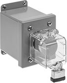 |
Hinged safety covers have a door that flips shut. They mount permanently and encase two button sizes—22 mm or 30 mm. Snap off the tabs around the mounting hole to fit 30 mm buttons.
Overall | ||||||||||||
|---|---|---|---|---|---|---|---|---|---|---|---|---|
For Panel Cutout Dia. | For Max. No. of Padlocks | For Max. Padlock Shackle Dia. | Wd. | Ht. | Dp. | Color | Label Included | Specs. Met | Each | |||
Lockout Cover | ||||||||||||
Plastic | ||||||||||||
| 7/8", 1 3/16", 22 mm, 30 mm | 1 | 5/16" | 1 3/4" | 1 3/4" | 1 7/8" | Clear | No | OSHA Compliant 29 CFR 1910.147 | 6913N93 | 000000 | ||
Forklift Lockout Sets with Padlock
 |
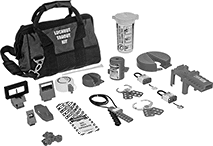
Prevent injuries while servicing a forklift—these kits come with everything you need to perform lockout tagout procedures. They include a lockout device that fully covers a gas cylinder and connectors, preventing accidental startup. An eye-catching red padlock, hasp, lockout, and carrying bag alert others to the maintenance and signal they should proceed with caution. These kits help you comply with OSHA 29 CFR 1910.147, which requires the battery or gas cylinder to be locked out during maintenance.
For Use With | Includes | Specs. Met | Each | ||
|---|---|---|---|---|---|
| Battery Cable Connectors, Electrical Plugs, Gas Cylinders | 10 Each: Cable Ties 1 Each: Plug Lockout 1 Each: 1/4" Shackle Diameter Keyed Differently Padlock with Label 1 Each: Lockout Hasp 10 Each: Forklift Inspection Tags 10 Each: Lockout Tags 20 Each: Safety Labels Carrying Case | OSHA Compliant 29 CFR 1910.147 | 6987N11 | 0000000 |
Keyed Alike Locking Door Knob Guards
 |
Choose this guard if you need several door knob guards that open with the same key. It blocks access to door knobs.
For Knob Dia. | ID | OD | Inside Dp. | For Door Swing Direction | Material | Each | ||
|---|---|---|---|---|---|---|---|---|
| 1 1/2" to 2 5/16" | 2 3/8" | 2 7/8" | 1 7/8" | Left, Right | Gray Painted Aluminum | 12035A13 | 000000 |
Keyed Differently Locking Door Knob Guards
|
Choose this guard if you need door knob guards that each open with a different key. It blocks access to door knobs.
For Knob Dia. | ID | OD | Inside Dp. | For Door Swing Direction | Material | Each | ||
|---|---|---|---|---|---|---|---|---|
| 1 1/2" to 2 5/16" | 2 3/8" | 2 7/8" | 1 7/8" | Left, Right | Gray Painted Aluminum | 12035A12 | 000000 |
Trailer Brake Lockouts
 |
Padlock and Tag Not Included |
Don’t worry about accidents and injuries—these lockouts stop accidental startups and sudden trailer movement, helping you comply with OSHA 29 CFR 1910.147 requirements. Clamp them around your trailer’s emergency air brake connection, also known as the glad hand or glad valve. Secure them with a padlock and add a lockout tag (both not included) so nobody can connect the trailer to a semi-truck.
Overall | |||||||||||
|---|---|---|---|---|---|---|---|---|---|---|---|
For Max. No. of Padlocks | For Max. Padlock Shackle Dia. | Lg. | Wd. | Ht. | Color | Label Included | Specs. Met | Each | |||
Lockout Cover | |||||||||||
Plastic | |||||||||||
| 1 | 9/32" | 4" | 3" | 2" | Red | No | OSHA Compliant 29 CFR 1910.147 | 7484N11 | 000000 | ||
Valve Lockout Sets with Padlocks
 |
Everything you need to safely lock out nearly every valve in your facility—these sets include adjustable ball valve and wheel lockouts along with a universal and cable lockout to tackle unusually shaped valves. Eye-catching red padlocks, hasps, and lockouts alert others to the maintenance and signal they should proceed with caution. Use them on compressed air, hydraulic fluid, fuel, and other potentially dangerous lines. These lockouts help you comply with OSHA 29 CFR 1910.147 requirements to prevent injuries from valves being accidentally opened during maintenance.
For Valve Control Type | Includes | Specs. Met | Each | ||
|---|---|---|---|---|---|
| Hand Wheel, Handle | 10 Each: Tags 1 Each: Cable Lockout 2 Each: Lockout Hasps Plastic Box 1 Each: Adjustable Ball Valve Lockout 1 Each: Universal Valve Lockout with Blocking Arm 10 Each: Zip Ties 3 Each: 1/4" Shackle Diameter Keyed Differently Padlocks 3 Valve Wheel Lockouts (1 Each that fits 1"-2 1/2", 2 1/2"-5", and 5"-6 1/2" Diameter Wheels) | OSHA Compliant 29 CFR 1910.147 | 7555N11 | 0000000 |
Wall Switch Lockouts
 | |
Clear Lockout | Lockout with Label |
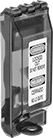
Mount these lockouts over a toggle- or rocker-style wall switch so it can’t be flipped during maintenance. They secure with a padlock to help you comply with OSHA 29 CFR 1910.147 requirements for locking out controls to prevent injuries. They’ll lock out your switch whether it’s on or off. When not in use, the cover flips up to allow normal operation. Made of plastic, these lockouts are corrosion resistant and nonconductive. That means they’re durable and safe for electrical applications. Use the screws on your switch cover plate to mount them in place.
Clear—Clear lockouts let you check your switch position at a glance.
Red—Red lockouts have a warning label on the front to alert others to the maintenance.
Overall | |||||||||||||
|---|---|---|---|---|---|---|---|---|---|---|---|---|---|
For Max. No. of Padlocks | For Max. Padlock Shackle Dia. | Lg. | Wd. | Dp. | Color | Label Included | Language | Message | Specs. Met | Each | |||
Lockout Cover | |||||||||||||
Plastic | |||||||||||||
| 1 | 5/16" | 3 7/8" | 13/16" | 15/16" | Clear | No | — | — | OSHA Compliant 29 CFR 1910.147 | 12135A111 | 000000 | ||
| 1 | 9/32" | 4 3/4" | 1 3/4" | 1 1/8" | Red | Yes | English/Spanish, English/French, | Danger—Locked Out—Do No Remove, Peligro—Cerrado—No Lo Quite Danger—Locked Out—Do No Remove, Danger—Verrouille—Ne Pas Enlever | OSHA Compliant 29 CFR 1910.147 | 12135A72 | 0000 | ||
