Filter by
Material
Overall Length
Mounting Location
Latching Distance
Overall Width
Draw Latch Type
Width
Length
DFARS Specialty Metals
Export Control Classification Number (ECCN)
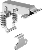
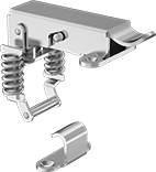
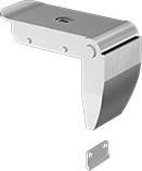
Tight-Hold Draw Latches
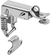
Style A | Style B | Style C |
 | ||
Style D | Style E | Style F |
 |  |  |
Style G | Style H | Replacement Latch Strike Plates |
Latches | Replacement Latch Strike Plates | ||||||||||||||||||||||||||||||||||||||||||||||||||||||||||||||||||||||||||||||||||||||||||||||||||
|---|---|---|---|---|---|---|---|---|---|---|---|---|---|---|---|---|---|---|---|---|---|---|---|---|---|---|---|---|---|---|---|---|---|---|---|---|---|---|---|---|---|---|---|---|---|---|---|---|---|---|---|---|---|---|---|---|---|---|---|---|---|---|---|---|---|---|---|---|---|---|---|---|---|---|---|---|---|---|---|---|---|---|---|---|---|---|---|---|---|---|---|---|---|---|---|---|---|---|---|
Overall | Mounting | ||||||||||||||||||||||||||||||||||||||||||||||||||||||||||||||||||||||||||||||||||||||||||||||||||
Style | Material | Appearance | Latching Distance | Lg. | Wd. | Projection | Wt. Cap., lb. | Fasteners Included | Screw Size | Each | Each | ||||||||||||||||||||||||||||||||||||||||||||||||||||||||||||||||||||||||||||||||||||||||
Screw On | |||||||||||||||||||||||||||||||||||||||||||||||||||||||||||||||||||||||||||||||||||||||||||||||||||
| A | 300 Series Stainless Steel | Polished | 3/8" | 1 7/16" | 1/2" | 5/16" | 200 | No | No. 2 | 0000000 | 00000 | 0000000 | 00000 | ||||||||||||||||||||||||||||||||||||||||||||||||||||||||||||||||||||||||||||||||||||||
| B | Zinc-Plated Steel | Dull | 1 5/16" | 2 3/4" | 1 3/16" | 7/16" | 400 | No | No. 6 | 0000000 | 0000 | 0000000 | 0000 | ||||||||||||||||||||||||||||||||||||||||||||||||||||||||||||||||||||||||||||||||||||||
| B | 300 Series Stainless Steel | Polished | 1 5/16" | 2 3/4" | 1 3/16" | 7/16" | 400 | No | No. 6 | 0000000 | 0000 | 0000000 | 0000 | ||||||||||||||||||||||||||||||||||||||||||||||||||||||||||||||||||||||||||||||||||||||
| C | Zinc-Plated Steel | Dull | 1 5/16" | 2 3/4" | 1 1/8" | 1/2" | 400 | No | No. 6 | 0000000 | 0000 | 0000000 | 0000 | ||||||||||||||||||||||||||||||||||||||||||||||||||||||||||||||||||||||||||||||||||||||
| C | 300 Series Stainless Steel | Polished | 1 5/16" | 2 3/4" | 1 1/8" | 1/2" | 400 | No | No. 6 | 0000000 | 00000 | 0000000 | 0000 | ||||||||||||||||||||||||||||||||||||||||||||||||||||||||||||||||||||||||||||||||||||||
| D | Zinc-Plated Steel | Dull | 1 5/16" | 2 3/4" | 1 1/8" | 3/8" | 400 | No | No. 6 | 0000000 | 0000 | 0000000 | 0000 | ||||||||||||||||||||||||||||||||||||||||||||||||||||||||||||||||||||||||||||||||||||||
| D | 300 Series Stainless Steel | Polished | 1 5/16" | 2 3/4" | 1 1/8" | 3/8" | 400 | No | No. 6 | 0000000 | 0000 | 0000000 | 0000 | ||||||||||||||||||||||||||||||||||||||||||||||||||||||||||||||||||||||||||||||||||||||
| E | 300 Series Stainless Steel | Polished | 1 5/16" | 1 7/16" | 1/2" | 1/4" | 400 | No | No. 5 | 0000000 | 00000 | 0000000 | 0000 | ||||||||||||||||||||||||||||||||||||||||||||||||||||||||||||||||||||||||||||||||||||||
| F | 304 Stainless Steel | Polished | 1 3/4" | 3 1/8" | 1 5/16" | 3/4" | Not Rated | No | No. 5 | 0000000 | 00000 | ——— | 0 | ||||||||||||||||||||||||||||||||||||||||||||||||||||||||||||||||||||||||||||||||||||||
| G | Zinc-Plated Steel | Dull | 1 1/4" | 2 3/8" | 1 3/8" | 1/2" | Not Rated | No | No. 6 | 0000000 | 0000 | ——— | 0 | ||||||||||||||||||||||||||||||||||||||||||||||||||||||||||||||||||||||||||||||||||||||
| G | Zinc-Plated Steel | Dull | 1 3/8" | 2 3/4" | 1 1/2" | 1/2" | Not Rated | No | No. 3 | 0000000 | 0000 | ——— | 0 | ||||||||||||||||||||||||||||||||||||||||||||||||||||||||||||||||||||||||||||||||||||||
| G | Zinc-Plated Steel | Dull | 1 3/8" | 3 1/2" | 1 15/16" | 5/8" | Not Rated | No | No. 10, No. 12 | 0000000 | 0000 | ——— | 0 | ||||||||||||||||||||||||||||||||||||||||||||||||||||||||||||||||||||||||||||||||||||||
| G | Zinc-Plated Steel | Dull | 1 7/16" | 3 7/8" | 1 7/8" | 5/8" | Not Rated | No | No. 5 | 0000000 | 00000 | ——— | 0 | ||||||||||||||||||||||||||||||||||||||||||||||||||||||||||||||||||||||||||||||||||||||
| G | 300 Series Stainless Steel | Polished | 1 3/8" | 3 13/16" | 1 15/16" | 5/8" | Not Rated | No | No. 5, No. 12 | 0000000 | 00000 | 0000000 | 0000 | ||||||||||||||||||||||||||||||||||||||||||||||||||||||||||||||||||||||||||||||||||||||
| G | 304 Stainless Steel | Polished | 7/8" | 2" | 1 1/4" | 3/8" | Not Rated | No | No. 3 | 0000000 | 0000 | ——— | 0 | ||||||||||||||||||||||||||||||||||||||||||||||||||||||||||||||||||||||||||||||||||||||
| G | 304 Stainless Steel | Polished | 1 3/8" | 2 11/16" | 1 1/2" | 9/16" | Not Rated | No | No. 5 | 0000000 | 0000 | ——— | 0 | ||||||||||||||||||||||||||||||||||||||||||||||||||||||||||||||||||||||||||||||||||||||
| G | 304 Stainless Steel | Polished | 1 3/8" | 3 3/4" | 1 13/16" | 5/8" | Not Rated | No | No. 5 | 0000000 | 00000 | ——— | 0 | ||||||||||||||||||||||||||||||||||||||||||||||||||||||||||||||||||||||||||||||||||||||
Weld On | |||||||||||||||||||||||||||||||||||||||||||||||||||||||||||||||||||||||||||||||||||||||||||||||||||
| C | Zinc-Plated Steel | Dull | 1 5/16" | 2 3/4" | 1 1/8" | 1/2" | 400 | — | — | 0000000 | 0000 | 0000000 | 0000 | ||||||||||||||||||||||||||||||||||||||||||||||||||||||||||||||||||||||||||||||||||||||
| C | 300 Series Stainless Steel | Polished | 1 5/16" | 2 3/4" | 1 1/8" | 1/2" | 400 | — | — | 0000000 | 00000 | 0000000 | 0000 | ||||||||||||||||||||||||||||||||||||||||||||||||||||||||||||||||||||||||||||||||||||||
| D | Zinc-Plated Steel | Dull | 1 5/16" | 2 3/4" | 1 1/8" | 3/8" | 400 | — | — | 0000000 | 0000 | 0000000 | 0000 | ||||||||||||||||||||||||||||||||||||||||||||||||||||||||||||||||||||||||||||||||||||||
| D | 300 Series Stainless Steel | Polished | 1 5/16" | 2 3/4" | 1 1/8" | 3/8" | 400 | — | — | 0000000 | 0000 | 0000000 | 0000 | ||||||||||||||||||||||||||||||||||||||||||||||||||||||||||||||||||||||||||||||||||||||
| H | Steel | Dull | 1 1/4" | 2 3/8" | 1 3/8" | 1/2" | Not Rated | — | — | 0000000 | 0000 | ——— | 0 | ||||||||||||||||||||||||||||||||||||||||||||||||||||||||||||||||||||||||||||||||||||||
Corner-Mount Tight-Hold Draw Latches
Overall | Mounting | Straight Strike Plate | 90° Angle Strike Plate | ||||||||||||||||||||||||||||||||||||||||||||||||||||||||||||||||||||||||||||||||||||||||||||||||
|---|---|---|---|---|---|---|---|---|---|---|---|---|---|---|---|---|---|---|---|---|---|---|---|---|---|---|---|---|---|---|---|---|---|---|---|---|---|---|---|---|---|---|---|---|---|---|---|---|---|---|---|---|---|---|---|---|---|---|---|---|---|---|---|---|---|---|---|---|---|---|---|---|---|---|---|---|---|---|---|---|---|---|---|---|---|---|---|---|---|---|---|---|---|---|---|---|---|---|---|
Material | Appearance | Latching Distance | Lg. | Wd. | Projection | Wt. Cap. | Fasteners Included | Screw Size | Each | Each | |||||||||||||||||||||||||||||||||||||||||||||||||||||||||||||||||||||||||||||||||||||||||
Draw Latches | |||||||||||||||||||||||||||||||||||||||||||||||||||||||||||||||||||||||||||||||||||||||||||||||||||
| 304 Stainless Steel | Polished | 1 1/8" | 2 1/4" | 1 9/16" | 5/8" | Not Rated | No | M4 | 0000000 | 000000 | 0000000 | 000000 | |||||||||||||||||||||||||||||||||||||||||||||||||||||||||||||||||||||||||||||||||||||||
Safety Catch | |||||||||||||||||||||||||||||||||||||||||||||||||||||||||||||||||||||||||||||||||||||||||||||||||||
| 304 Stainless Steel | Polished | 2 3/16" | 2 3/8" | 1 11/16" | 5/8" | Not Rated | No | M3 | 0000000 | 00000 | ——— | 0 | |||||||||||||||||||||||||||||||||||||||||||||||||||||||||||||||||||||||||||||||||||||||
| 304 Stainless Steel | Polished | 2 9/16" | 3 5/8" | 2 1/4" | 3/4" | Not Rated | No | M4 | 0000000 | 00000 | 0000000 | 00000 | |||||||||||||||||||||||||||||||||||||||||||||||||||||||||||||||||||||||||||||||||||||||
| 304 Stainless Steel | Polished | 2 13/16" | 4 3/8" | 2 1/2" | 1" | Not Rated | No | M5 | 0000000 | 00000 | 0000000 | 00000 | |||||||||||||||||||||||||||||||||||||||||||||||||||||||||||||||||||||||||||||||||||||||
Corner-Mount Draw Latches
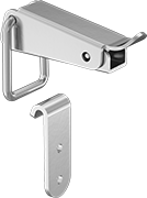 | 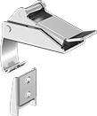 | 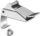 | 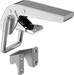 |
Style A | Style B | Style C | Style D |
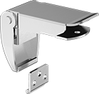 | 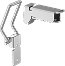 |  | |
Style E | Style F | Style G |
Overall | Mounting | ||||||||||||||||||||||||||||||||||||||||||||||||||||||||||||||||||||||||||||||||||||||||||||||||||
|---|---|---|---|---|---|---|---|---|---|---|---|---|---|---|---|---|---|---|---|---|---|---|---|---|---|---|---|---|---|---|---|---|---|---|---|---|---|---|---|---|---|---|---|---|---|---|---|---|---|---|---|---|---|---|---|---|---|---|---|---|---|---|---|---|---|---|---|---|---|---|---|---|---|---|---|---|---|---|---|---|---|---|---|---|---|---|---|---|---|---|---|---|---|---|---|---|---|---|---|
Style | Material | Appearance | Latching Distance | Lg. | Wd. | Projection | Wt. Cap., lb. | Fasteners Included | Screw Size | Each | |||||||||||||||||||||||||||||||||||||||||||||||||||||||||||||||||||||||||||||||||||||||||
Screw On | |||||||||||||||||||||||||||||||||||||||||||||||||||||||||||||||||||||||||||||||||||||||||||||||||||
| A | Zinc-Plated Steel | Dull | 1" | 3 3/16" | 1 9/16" | 1 1/16" | 310 | No | M5 | 00000000 | 000000 | ||||||||||||||||||||||||||||||||||||||||||||||||||||||||||||||||||||||||||||||||||||||||
| B | 304 Stainless Steel | Polished | 13/16" | 2 1/8" | 15/16" | 7/8" | 155 | No | M4 | 00000000 | 00000 | ||||||||||||||||||||||||||||||||||||||||||||||||||||||||||||||||||||||||||||||||||||||||
| C | 304 Stainless Steel | Polished | 13/16" | 2 1/8" | 15/16" | 7/8" | 155 | No | M4 | 00000000 | 00000 | ||||||||||||||||||||||||||||||||||||||||||||||||||||||||||||||||||||||||||||||||||||||||
| D | 304 Stainless Steel | Polished | 1 7/16" | 5" | 2 3/16" | 1 13/16" | 895 | No | M6 | 00000000 | 00000 | ||||||||||||||||||||||||||||||||||||||||||||||||||||||||||||||||||||||||||||||||||||||||
| D | 304 Stainless Steel | Polished | 2 3/8" | 6 15/16" | 2 5/8" | 2 3/16" | 1,010 | No | M6 | 00000000 | 00000 | ||||||||||||||||||||||||||||||||||||||||||||||||||||||||||||||||||||||||||||||||||||||||
| D | 304 Stainless Steel | Polished | 2 3/8" | 9" | 2 5/8" | 2 3/8" | 1,010 | No | M6 | 00000000 | 00000 | ||||||||||||||||||||||||||||||||||||||||||||||||||||||||||||||||||||||||||||||||||||||||
| E | 304 Stainless Steel | Polished | 11/16" | 2 1/8" | 1 1/16" | 7/16" | Not Rated | No | M3 | 00000000 | 00000 | ||||||||||||||||||||||||||||||||||||||||||||||||||||||||||||||||||||||||||||||||||||||||
| E | 304 Stainless Steel | Polished | 15/16" | 2 5/8" | 1 5/16" | 1/2" | Not Rated | No | M4 | 00000000 | 00000 | ||||||||||||||||||||||||||||||||||||||||||||||||||||||||||||||||||||||||||||||||||||||||
| E | 304 Stainless Steel | Polished | 1 5/16" | 3 1/4" | 1 5/8" | 9/16" | 115 | No | M4 | 00000000 | 00000 | ||||||||||||||||||||||||||||||||||||||||||||||||||||||||||||||||||||||||||||||||||||||||
| F | 304 Stainless Steel | Polished | 2 1/16" | 2 7/16" | 1 1/8" | 3/4" | 75 | No | M4 | 00000000 | 00000 | ||||||||||||||||||||||||||||||||||||||||||||||||||||||||||||||||||||||||||||||||||||||||
| G | 304 Stainless Steel | Polished | 1 7/8" | 2 1/4" | 1 13/16" | 1/2" | 25 | No | M4 | 00000000 | 00000 | ||||||||||||||||||||||||||||||||||||||||||||||||||||||||||||||||||||||||||||||||||||||||
Tight-Hold Padlockable Draw Latches
 |  |  |
Style A | Style B | Replacement Latch Strike Plates |
Latches | Replacement Latch Strike Plates | |||||||||||||||
|---|---|---|---|---|---|---|---|---|---|---|---|---|---|---|---|---|
Overall | Mounting | |||||||||||||||
Style | Material | Appearance | Latching Distance | Lg. | Wd. | Projection | Wt. Cap. | For Max. Padlock Shackle Dia. | Fasteners Included | Screw Size | Each | Each | ||||
| A | Zinc-Plated Steel | Polished | 1 1/16" | 3" | 1 3/8" | 13/16" | Not Rated | 5/16" | No | No. 6 | 0000000 | 00000 | 0000000 | 00000 | ||
| A | Zinc-Plated Steel | Polished | 1 1/4" | 3 5/8" | 1 13/16" | 15/16" | Not Rated | 3/8" | No | No. 10, No. 12 | 0000000 | 00000 | 0000000 | 0000 | ||
| B | Zinc-Plated Steel | Polished | 4 1/16" | 3 3/16" | 1 7/8" | 7/8" | Not Rated | 3/8" | No | No. 10 | 0000000 | 0000 | 0000000 | 0000 | ||
| B | 300 Series Stainless Steel | Dull | 4 1/16" | 3 3/16" | 1 7/8" | 7/8" | Not Rated | 3/8" | No | No. 10 | 0000000 | 00000 | 0000000 | 0000 | ||
Keyed Corner-Mount Draw Locks
Overall | Mounting | Straight Strike Plate | ||||||||||||
|---|---|---|---|---|---|---|---|---|---|---|---|---|---|---|
Material | Appearance | Latching Distance | Lg. | Wd. | Projection | Wt. Cap. | Fasteners Included | Screw Size | Key No. | No. of Keys Included | Each | |||
| 304 Stainless Steel | Polished | 3/4" | 2 1/16" | 1" | 7/16" | Not Rated | No | No. 5 | 0200 | 2 | 0000000 | 000000 | ||
| 304 Stainless Steel | Polished | 1" | 2 9/16" | 1 1/4" | 1/2" | Not Rated | No | No. 8 | 0200 | 2 | 0000000 | 00000 | ||
| 304 Stainless Steel | Polished | 1 1/4" | 3 1/4" | 1 9/16" | 5/8" | Not Rated | No | No. 8 | 0200 | 2 | 0000000 | 00000 | ||
Padlockable Draw Latches
 |  |  |  |
Style B | Style G | Style H | Style J |
Latches | Replacement Latch Strike Plates | ||||||||||||||||||||||||||||||||||||||||||||||||||||||||||||||||||||||||||||||||||||||||||||||||||
|---|---|---|---|---|---|---|---|---|---|---|---|---|---|---|---|---|---|---|---|---|---|---|---|---|---|---|---|---|---|---|---|---|---|---|---|---|---|---|---|---|---|---|---|---|---|---|---|---|---|---|---|---|---|---|---|---|---|---|---|---|---|---|---|---|---|---|---|---|---|---|---|---|---|---|---|---|---|---|---|---|---|---|---|---|---|---|---|---|---|---|---|---|---|---|---|---|---|---|---|
Overall | Mounting | ||||||||||||||||||||||||||||||||||||||||||||||||||||||||||||||||||||||||||||||||||||||||||||||||||
Style | Material | Appearance | Latching Distance | Lg. | Wd. | Projection | Wt. Cap., lb. | For Max. Padlock Shackle Dia. | Fasteners Included | Screw Size | Pkg. Qty. | Pkg. | Each | ||||||||||||||||||||||||||||||||||||||||||||||||||||||||||||||||||||||||||||||||||||||
Screw On | |||||||||||||||||||||||||||||||||||||||||||||||||||||||||||||||||||||||||||||||||||||||||||||||||||
| B | Zinc-Plated Steel | Polished | 2 9/16" | 2 1/2" | 7/8" | 3/4" | Not Rated | 1/4" | No | No. 6 | 1 | 0000000 | 00000 | 0000000 | 00000 | ||||||||||||||||||||||||||||||||||||||||||||||||||||||||||||||||||||||||||||||||||||
| B | 300 Series Stainless Steel | Dull | 2 9/16" | 2 1/2" | 7/8" | 3/4" | Not Rated | 1/4" | No | No. 6 | 1 | 0000000 | 00000 | 0000000 | 0000 | ||||||||||||||||||||||||||||||||||||||||||||||||||||||||||||||||||||||||||||||||||||
| G | 300 Series Stainless Steel | Dull | 1 5/16" | 2 3/4" | 1 3/16" | 15/16" | 400 | 3/8" | No | No. 6 | 1 | 0000000 | 00000 | ——— | 0 | ||||||||||||||||||||||||||||||||||||||||||||||||||||||||||||||||||||||||||||||||||||
| H | Zinc-Plated Steel | Polished | 3 7/8" | 3 7/8" | 1 1/4" | 15/16" | Not Rated | 3/8" | No | No. 10 | 1 | 0000000 | 0000 | 0000000 | 0000 | ||||||||||||||||||||||||||||||||||||||||||||||||||||||||||||||||||||||||||||||||||||
| H | 300 Series Stainless Steel | Dull | 3 7/8" | 3 7/8" | 1 1/4" | 15/16" | Not Rated | 3/8" | No | No. 10 | 1 | 0000000 | 00000 | 0000000 | 0000 | ||||||||||||||||||||||||||||||||||||||||||||||||||||||||||||||||||||||||||||||||||||
| J | Zinc-Plated Steel | Polished | 4 1/2" | 3 5/8" | 1 7/8" | 7/8" | Not Rated | 1/4" | No | No. 10 | 1 | 0000000 | 00000 | 0000000 | 0000 | ||||||||||||||||||||||||||||||||||||||||||||||||||||||||||||||||||||||||||||||||||||
Tight-Hold Draw Latches with Safety Catch
 |  |  |
Style A | Style B | Replacement Latch Strike Plates |
Latches | Replacement Latch Strike Plates | ||||||||||||||||||||||||||||||||||||||||||||||||||||||||||||||||||||||||||||||||||||||||||||||||||
|---|---|---|---|---|---|---|---|---|---|---|---|---|---|---|---|---|---|---|---|---|---|---|---|---|---|---|---|---|---|---|---|---|---|---|---|---|---|---|---|---|---|---|---|---|---|---|---|---|---|---|---|---|---|---|---|---|---|---|---|---|---|---|---|---|---|---|---|---|---|---|---|---|---|---|---|---|---|---|---|---|---|---|---|---|---|---|---|---|---|---|---|---|---|---|---|---|---|---|---|
Overall | Mounting | ||||||||||||||||||||||||||||||||||||||||||||||||||||||||||||||||||||||||||||||||||||||||||||||||||
Style | Material | Appearance | Latching Distance | Lg. | Wd. | Projection | Wt. Cap., lb. | Fasteners Included | Screw Size | Each | Each | ||||||||||||||||||||||||||||||||||||||||||||||||||||||||||||||||||||||||||||||||||||||||
Screw On | |||||||||||||||||||||||||||||||||||||||||||||||||||||||||||||||||||||||||||||||||||||||||||||||||||
| A | 300 Series Stainless Steel | Polished | 1 11/16" | 2 3/4" | 1 1/8" | 5/8" | 400 | No | No. 6 | 0000000 | 000000 | 0000000 | 00000 | ||||||||||||||||||||||||||||||||||||||||||||||||||||||||||||||||||||||||||||||||||||||
| B | 304 Stainless Steel | Polished | 1 11/16" | 3 1/4" | 1 5/16" | 3/4" | Not Rated | No | M4 | 0000000 | 00000 | ——— | 0 | ||||||||||||||||||||||||||||||||||||||||||||||||||||||||||||||||||||||||||||||||||||||
| B | 304 Stainless Steel | Polished | 1 13/16" | 3 15/16" | 2 1/16" | 3/4" | Not Rated | No | M4 | 0000000 | 00000 | ——— | 0 | ||||||||||||||||||||||||||||||||||||||||||||||||||||||||||||||||||||||||||||||||||||||
Weld On | |||||||||||||||||||||||||||||||||||||||||||||||||||||||||||||||||||||||||||||||||||||||||||||||||||
| A | Zinc-Plated Steel | Dull | 1 11/16" | 2 3/4" | 1 1/8" | 5/8" | 400 | — | — | 0000000 | 00000 | ——— | 0 | ||||||||||||||||||||||||||||||||||||||||||||||||||||||||||||||||||||||||||||||||||||||
| A | 300 Series Stainless Steel | Polished | 1 11/16" | 2 3/4" | 1 1/8" | 5/8" | 400 | — | — | 0000000 | 00000 | ——— | 0 | ||||||||||||||||||||||||||||||||||||||||||||||||||||||||||||||||||||||||||||||||||||||
Corner-Mount Tight-Hold Padlockable Draw Latches with Safety Catch
Overall | Mounting | Straight Strike Plate | ||||||||||||
|---|---|---|---|---|---|---|---|---|---|---|---|---|---|---|
Material | Appearance | Latching Distance | Lg. | Wd. | Projection | Wt. Cap. | For Max. Padlock Shackle Dia. | Fasteners Included | Screw Size | Features | Each | |||
| 304 Stainless Steel | Polished | 1 1/8" | 2 9/16" | 1 9/16" | 5/8" | Not Rated | 3/16" | No | M4 | Safety Catch | 0000000 | 000000 | ||
