


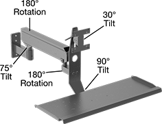
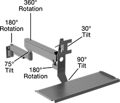
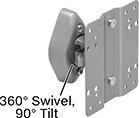
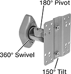
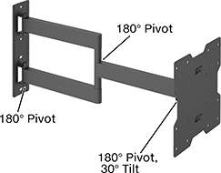
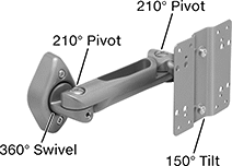
Heavy Duty Positioning Arms
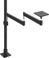 |  |
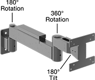
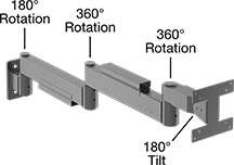
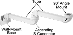
Arm Built with Floor- and Bench-Mount Pole Base, Pole, Pole-to-Pin Adapter, Two Rigid Connectors, and Pivoting Mounting Plate | Arm Built with Wall-Mount Pin Base, Two Rigid Connectors, and Pivoting Mounting Plate |
 |  |
Complete Arms Screw On Style A | Complete Arms Screw On Style B |
 |  |
Complete Arms Screw On Style C | Complete Arms Screw On Style D |
 |  |
Complete Arms Screw On Style E | Complete Arms Screw On Style F |
 |  |
Complete Arms Screw On Style G | Complete Arms Screw On Style H |
| |
Screw On Style A | Screw On Style B |
| |
Screw On Style C | Screw On Style D |
| |
Screw On Style E | Screw On Style F |
| |
Screw On Style G | Screw On Style H |
Load Capacity, lb. | Base | Attaching End | ||||||||||||||||||
|---|---|---|---|---|---|---|---|---|---|---|---|---|---|---|---|---|---|---|---|---|
Style | Mounting Location | Max. Projection | Min. | Max. | Material | Color | Mounting Fasteners Included | Lg. | Wd. | No. of Mounting Holes | Mounting Hole Dia. | Plate Lg. | Plate Wd. | No. of Mounting Holes | Mounting Hole Dia. | Includes | Each | |||
Screw On | ||||||||||||||||||||
| A | Wall | 27" | — | 100 | Powder-Coated Steel | Black | No | 6" | 6" | 4 | 13/32" | 6" | 6" | 4 | 13/32" | Pivoting Mounting Plate, (2) Rigid Connectors, Pin Base | 5164T1 | 0000000 | ||
| A | Wall | 39" | — | 100 | Powder-Coated Steel | Black | No | 6" | 6" | 4 | 13/32" | 6" | 6" | 4 | 13/32" | Pivoting Mounting Plate, (2) Rigid Connectors, Pin Base | 5164T2 | 000000 | ||
| B | Wall | 7" | — | 25 | Powder-Coated Steel | Black | No | 4 1/2" | 2" | 2 | 13/32" | 4 1/2" | 4 1/2" | 8 | 3/16" | Flat-Panel Monitor Mounting Plate, Pin Base | 5164T31 | 000000 | ||
| C | Wall | 19" | — | 25 | Powder-Coated Steel | Black | No | 4 1/2" | 2" | 2 | 13/32" | 4 1/2" | 4 1/2" | 8 | 3/16" | Flat-Panel Monitor Mounting Plate, Rigid Connector, Cable Protector, Pin Base | 5164T32 | 000000 | ||
| D | Wall | 31" | — | 25 | Powder-Coated Steel | Black | No | 4 1/2" | 2" | 2 | 13/32" | 4 1/2" | 4 1/2" | 8 | 3/16" | Flat-Panel Monitor Mounting Plate, (2) Rigid Connectors, (2) Cable Protectors, Pin Base | 5164T33 | 000000 | ||
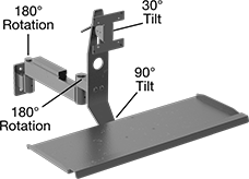
| E | Wall | 29" | — | 25 | Powder-Coated Steel | Black | No | 4 1/2" | 2" | 2 | 13/32" | 4 1/2" | 4 1/2" | 8 | 3/16" | Flat-Panel Monitor Mounting Plate, Keyboard Tray, Rigid Connector, Cable Protector, Pin Base | 5164T34 | 000000 | ||
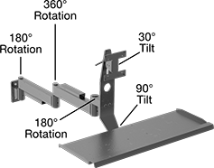
| F | Wall | 41" | — | 25 | Powder-Coated Steel | Black | No | 4 1/2" | 2" | 2 | 13/32" | 4 1/2" | 4 1/2" | 8 | 3/16" | Flat-Panel Monitor Mounting Plate, Keyboard Tray, (2) Rigid Connectors, (2) Cable Protectors, Pin Base | 5164T35 | 000000 | ||
| G | Wall | 36" | 4 | 21 | Powder-Coated Steel | Black | No | 6" | 2 1/2" | 3 | 13/32" | 4 1/2" | 4 1/2" | 8 | 3/16" | Flat-Panel Monitor Mounting Plate, Keyboard Tray, Counterbalancing Connector, Cable Protector, Pin Base | 5164T38 | 000000 | ||
| H | Wall | 43" | 18 | 43 | Powder-Coated Steel | Black | No | 4 1/2" | 2" | 2 | 13/32" | 4 1/2" | 4 1/2" | 8 | 3/16" | Flat-Panel Monitor Mounting Plate, Keyboard Tray, Rigid Connector, Counterbalancing Connector, (2) Cable Protectors, Pin Base | 5164T37 | 000000 | ||
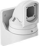
 |  |
Wall- and T-Slot Rail-Mount Pin Base | Wall-Mount Pin Base |
For T-Slot Rail Ht. | Mounting | |||||||||||||||
|---|---|---|---|---|---|---|---|---|---|---|---|---|---|---|---|---|
Mounting Location | Single | Double, Quad | Lg. | Wd. | Ht. | For Pin Dia. | Max. Load Cap., lb. | Material | Color | Fasteners Included | No. of Holes | Hole Dia. | Each | |||
Screw On | ||||||||||||||||
| T-Slotted Rail, Wall | 1 1/2", 30 mm, 40 mm, 45 mm | 3", 60 mm, 80 mm, 90 mm | 3" | 2" | 4 1/2" | 7/8" | 50 | Powder-Coated Steel | Black | No | 2 | 13/32" | 5164T942 | 000000 | ||
| T-Slotted Rail, Wall | 1 1/2", 30 mm, 40 mm, 45 mm | 3", 60 mm, 80 mm, 90 mm | 7 1/8" | 2 1/2" | 6" | 7/8" | 75 | Powder-Coated Steel | Black | No | 3 | 13/32" | 5164T943 | 000000 | ||
| Wall | — | — | 1 7/8" | 6" | 6" | 7/8" | 100 | Powder-Coated Steel | Black | No | 4 | 13/32" | 5164T52 | 000000 | ||
 |
Screw On Wall Mount |
Mounting | ||||||||||||||
|---|---|---|---|---|---|---|---|---|---|---|---|---|---|---|
Mounting Location | Lg. | Wd. | Ht. | For Pole Dia. | Max. Load Cap., lb. | Material | Color | Fasteners Included | No. of Holes | Hole Dia. | Each | |||
Screw On | ||||||||||||||
| Wall | 3" | 4 1/2" | 3" | 2" | 100 | Powder-Coated Aluminum | Black | No | 4 | 5/16" | 5164T951 | 0000000 | ||
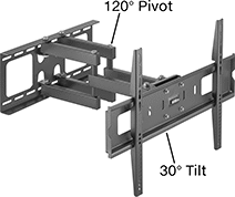
Wall Monitor Mounts
 |  |
Style A | Style B |
 |  |
Style C | Style D |
 |  |
Style E | Style F |
| |
Style A | Style B |
Base | ||||||||||||||
|---|---|---|---|---|---|---|---|---|---|---|---|---|---|---|
Style | For Monitor Size | Max. Load Cap., lb. | Max. Projection | Material | Lg. | Wd. | Monitor Mounting Pattern Compatibility | Mounting Fasteners Included | Adjustment Movement | Features | Each | |||
Screw-On Base | ||||||||||||||
| A | 10" to 30" | 40 | 3" | Silver Powder-Coated Steel | 3 13/16" | 2 7/16" | VESA 75 × 75, VESA 100 × 100 | Yes | Swivel, Tilt | Swivel Plate | 4628T11 | 000000 | ||
| B | 10" to 30" | 40 | 4 11/16" | Silver Powder-Coated Steel | 3 13/16" | 2 7/16" | VESA 75 × 75, VESA 100 × 100 | Yes | Pivot, Swivel, Tilt | Swivel Plate | 4628T12 | 00000 | ||
| |
Style C | Style D |
| |
Style E |
Projection | Base | ||||||||||||||
|---|---|---|---|---|---|---|---|---|---|---|---|---|---|---|---|
Style | For Monitor Size | Max. Load Cap., lb. | Min. | Max. | Material | Lg. | Wd. | Monitor Mounting Pattern Compatibility | Mounting Fasteners Included | Adjustment Movement | Certification | Each | |||
Screw-On Base | |||||||||||||||
| C | 13" to 27" | 30 | 4 1/8" | 15 15/16" | Black Powder-Coated Steel | 4 5/8" | 4 5/8" | VESA 75 × 75, VESA 100 × 100 | Yes | Extend, Pivot, Tilt | — | 1133A6 | 000000 | ||
| C | 17" to 42" | 75 | 2 1/4" | 22 1/16" | Black Powder-Coated Steel | 9 5/16" | 8 3/4" | VESA 75 × 75, VESA 100 × 100, VESA 200 × 200 | Yes | Extend, Pivot, Tilt | — | 1133A4 | 00000 | ||
| D | 37" to 70" | 165 | 4 9/16" | 20 5/8" | Black Powder-Coated Steel | 31 15/16" | 8 3/4" | VESA 200 × 200, VESA 300 × 300, VESA 400 × 400, VESA 600 × 600 | Yes | Extend, Pivot, Tilt | — | 1133A5 | 000000 | ||
| E | 60" to 100" | 275 | 2 3/4" | 24 5/8" | Black Powder-Coated Steel | 37" | 15 15/16" | VESA 200 × 200, VESA 300 × 300, VESA 400 × 200, VESA 400 × 400, VESA 500 × 500, VESA 600 × 400, VESA 600 × 600, VESA 600 × 900, VESA 800 × 400, VESA 800 × 600 | Yes | Extend, Pivot, Tilt | C-UL Listed, UL Listed | 1133A112 | 000000 | ||
|
Style F |
Projection | Base | ||||||||||||||
|---|---|---|---|---|---|---|---|---|---|---|---|---|---|---|---|
Style | For Monitor Size | Max. Load Cap., lb. | Min. | Max. | Material | Lg. | Wd. | Monitor Mounting Pattern Compatibility | Mounting Fasteners Included | Adjustment Movement | Features | Each | |||
Screw-On Base | |||||||||||||||
| F | 10" to 30" | 40 | 3 5/8" | 10 11/16" | Silver Powder-Coated Steel | 3 13/16" | 2 7/16" | VESA 75 × 75, VESA 100 × 100 | Yes | Extend, Pivot, Swivel, Tilt, Up and Down | Swivel Plate | 4628T13 | 000000 | ||
Suspension Positioning Arms for Enclosures
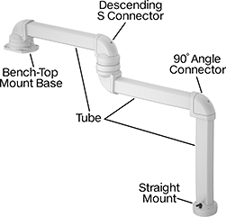 | 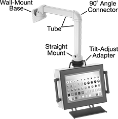 |
Example Configuration | All Components Sold Separately |
 | |
Example Configuration |
 |
Wall Mount |
For Tube | Mounting Plate | ||||||||||||||
|---|---|---|---|---|---|---|---|---|---|---|---|---|---|---|---|
Adjustment Movement | Max. Range of Motion | Ht. | Wd. | Ht. | Lg. | Wd. | Hole Dia. | Material | Color | Mounting Fasteners Included | Features | Each | |||
Wall Mount | |||||||||||||||
| Pivot | 230° | 3 1/2" | 2 1/2" | 10" | 7 1/8" | 5 5/8" | 0.389" | Powder-Coated Aluminum | White | Yes | Cable Routing Hole, Locking Pins | 7255N12 | 0000000 | ||
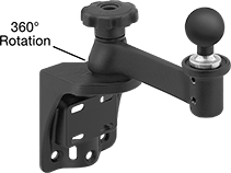
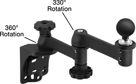
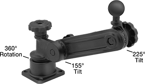
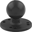
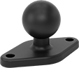
Ball-Grip Positioning Arms
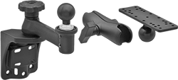 |
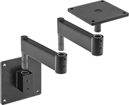
Arm Built with Rotating Complete Arm with Ball, Rigid Connector, and Universal Mounting Plate |
 |  |
Any-Which-Way | Rotating/Tilting Arm |
Base | Attaching End | ||||||||||||||||
|---|---|---|---|---|---|---|---|---|---|---|---|---|---|---|---|---|---|
Max. Projection | Ht. | Max. Load Cap., lb. | Material | Color | Mounting Fasteners Included | Dia. | No. of Mounting Holes | Mounting Hole Dia. | Plate Dia. | Mounting Hole Dia. | Range of Motion | Max. Tilt Range of Motion | No. of Mounting Holes | Each | |||
Any-Which-Way | |||||||||||||||||
| — | 7 3/8" | 1 | Plastic | Black | No | 2 1/2" | 4 | 13/64" | 2 1/2" | 13/64" | — | — | 4 | 5031T132 | 000000 | ||
Rotating/Tilting | |||||||||||||||||
| 7 1/4" | — | 3 | Powder-Coated Aluminum | Black | No | 2 7/16" | 7 | 3/16" | 2 7/16" | 3/16" | 360° | 180° | 7 | 5031T61 | 00000 | ||
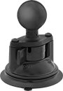
 |  |
Rotating-Ball Arm | Extended-Reach Rotating Ball Arm |
Base | ||||||||||||||||
|---|---|---|---|---|---|---|---|---|---|---|---|---|---|---|---|---|
Max. Projection | Ht. | Ball Dia. | Max. Load Cap., lb. | Material | Ball Material | Color | Mounting Fasteners Included | Lg. | Wd. | No. of Mounting Holes | Mounting Hole Dia. | Max. Range of Motion | Each | |||
Rotating with Ball | ||||||||||||||||
| 9 1/4" | 9" | 1 1/2" | 3 | Powder-Coated Aluminum | Rubber | Black | No | 4 3/4" | 3 7/8" | 6 | 11/32" | — | 5031T77 | 0000000 | ||
Extended-Reach Rotating with Ball | ||||||||||||||||
| 15 1/4" | 11 1/4" | 1 1/2" | 3 | Powder-Coated Aluminum | Rubber | Black | No | 4 3/4" | 3 7/8" | 6 | 11/32" | 330° | 5031T25 | 000000 | ||
 |
Rotating/Tilting-Ball Arm |
Base | ||||||||||||||||
|---|---|---|---|---|---|---|---|---|---|---|---|---|---|---|---|---|
Max. Projection | Ht. | Ball Dia. | Max. Load Cap., lb. | Material | Ball Material | Color | Mounting Fasteners Included | Lg. | Wd. | No. of Mounting Holes | Mounting Hole Dia. | Max. Tilt Range of Motion | Each | |||
Rotating/Tilting with Ball | ||||||||||||||||
| 14 1/2" | 14 1/2" | 1 1/2" | 3 | Powder-Coated Aluminum | Rubber | Black | No | 3 7/16" | 3 7/16" | 4 | 11/32" | 155° | 5031T26 | 0000000 | ||
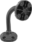
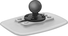
 |  |
Round Base | Diamond Base |
Mounting | Base | |||||||||||||||
|---|---|---|---|---|---|---|---|---|---|---|---|---|---|---|---|---|
Ht. | Ball Dia. | Max. Load Cap., lb. | Material | Ball Material | Color | Fasteners Included | Pattern Compatibility | No. of Holes | Hole Dia. | Dia. | Lg. | Wd. | Each | |||
Round Base | ||||||||||||||||
| 1 1/2" | 1" | 1 | Powder-Coated Aluminum | Rubber | Black | No | AMPS | 7 | 7/32" | 2 7/16" | — | — | 5031T102 | 000000 | ||
| 2 1/8" | 1 1/2" | 3 | Powder-Coated Aluminum | Rubber | Black | No | AMPS | 7 | 7/32" | 2 1/2" | — | — | 5031T63 | 00000 | ||
| 3 1/16" | 2 1/4" | 5 | Powder-Coated Aluminum | Rubber | Black | No | AMPS | 4 | 7/32" | 2 7/16" | — | — | 5031T113 | 00000 | ||
Diamond Base | ||||||||||||||||
| 1 1/2" | 1" | 1 | Powder-Coated Aluminum | Rubber | Black | No | AMPS | 2 | 7/32" | — | 2 7/16" | 1 5/16" | 5031T105 | 00000 | ||

 |
Base | |||||||||||
|---|---|---|---|---|---|---|---|---|---|---|---|
Ht. | Ball Dia. | Max. Load Cap., lb. | Material | Ball Material | Color | Lg. | Wd. | Each | |||
Rotate, Tilt, Side to Side, In/Out | |||||||||||
| 2 3/4" | 1 1/2" | 3 | Plastic | Rubber | Gray | 5 3/8" | 7" | 5031T57 | 000000 | ||
 |
AMPS and VESA 75 |
Mounting | |||||||||
|---|---|---|---|---|---|---|---|---|---|
Lg. | Wd. | Material | Color | Fasteners Included | Pattern Compatibility | Each | |||
Rotate, Tilt, Side to Side, In/Out | |||||||||
| 6" | 8 9/16" to 11 1/8" | Plastic | Black | Yes | AMPS VESA 75 × 75 | 5031T569 | 000000 | ||
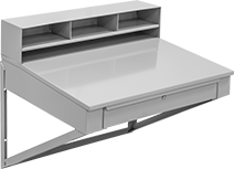
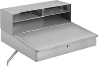
Wall-Mount Desks
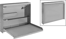 |  |  |
Style A | Style B | Style C |
Beige | Gray | White |
|
Beige |
Gray |
White |
Overall | Work Surface | Mounting Holes | ||||||||||||||
|---|---|---|---|---|---|---|---|---|---|---|---|---|---|---|---|---|
Wd. | Dp. | Ht. | Style | Dp. | Top Wt. Cap., lb. | Projection When Folded | Side Stop Ht. | No. of | Dia. | Mounting Fasteners Included | Assembly | Choose a Color | Each | |||
Powder-Coated Steel | ||||||||||||||||
| 20" | 15 1/4" | 16 3/8" | Flat | 13 1/2" | 25 | 3 3/8" | 1" | 2 | 3/16" | Yes | Assembled | Beige, Gray, White | 4796T15 | 0000000 | ||
Stainless Steel | ||||||||||||||||
| 20" | 15 1/4" | 16 3/8" | Flat | 13 1/2" | 25 | 3 3/8" | 1" | 2 | 3/16" | Yes | Assembled | — | 4796T21 | 000000 | ||
| |
Gray |
Overall | Work Surface | Drawers | Mounting Holes | Locks | |||||||||||||||||
|---|---|---|---|---|---|---|---|---|---|---|---|---|---|---|---|---|---|---|---|---|---|
Wd. | Dp. | Ht. | Style | Dp. | Top Wt. Cap., lb. | Dp. | Wd. | Ht. | Wt. Cap., lb. | No. of | Dia. | Number of | Location | Included | Mounting Fasteners Included | Assembly | Color | Each | |||
Powder-Coated Steel | |||||||||||||||||||||
| 34 1/2" | 30" | 32" | Sloped | 22" | 200 | 28" | 24" | 3 1/2" | 100 | 4 | 7/16" | 1 | Drawer | Yes | Yes | Assembled | Gray | 4808T15 | 0000000 | ||
| |
Gray |
Overall | Work Surface | Locks | ||||||||||||||
|---|---|---|---|---|---|---|---|---|---|---|---|---|---|---|---|---|
Wd. | Dp. | Ht. | Style | Dp. | Top Wt. Cap., lb. | Number of | Location | Included | Mounting Hole Diameter (No. of) | Mounting Fasteners Included | Assembly | Color | Each | |||
Powder-Coated Steel | ||||||||||||||||
| 24 1/2" | 27 1/4" | 11 7/8" | Sloped | 13 1/2" | 100 | 1 | Top Compartment | Yes | 1/4" (2), 1/4" (4) | No | Assembled | Gray | 4014T48 | 0000000 | ||
Stainless Steel | ||||||||||||||||
| 24 1/2" | 27 1/4" | 11 7/8" | Sloped | 13 1/2" | 150 | 1 | Top Compartment | Yes | 1/4" (2), 1/4" (4) | No | Assembled | — | 4014T47 | 000000 | ||
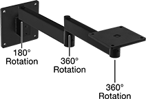
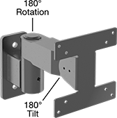
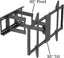
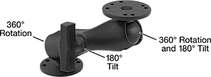
Positioning Arms
 | 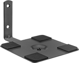 |
Pivoting Arm | Fixed Arm |
Base | Attaching End | |||||||||||||||||
|---|---|---|---|---|---|---|---|---|---|---|---|---|---|---|---|---|---|---|
Max. Projection | Max. Load Cap., lb. | Material | Color | Mounting Fasteners Included | Lg. | Wd. | No. of Mounting Holes | Mounting Hole Dia. | Mounting Hole Dia. | Max. Tilt Range of Motion | Plate Lg. | Plate Wd. | No. of Mounting Holes | Features | Each | |||
Pivoting Arm | ||||||||||||||||||
| 13" | 8 | Anodized Aluminum | Black | Yes | 3" | 2" | 4 | 17/64" | 13/64" | 45° | 6" | 4" | 12 | — | 1592A31 | 0000000 | ||
| 20" | 8 | Anodized Aluminum | Black | Yes | 3" | 2" | 4 | 17/64" | 13/64" | 45° | 6" | 4" | 12 | — | 1592A32 | 000000 | ||
Fixed Arm | ||||||||||||||||||
| 8 1/2" | 12 | Powder-Coated Steel | Black | No | 4 1/2" | 1 1/4" | 2 | 3/16" | 1/4" | — | 6" | 6" | 4 | Slip-Resistant Plate Pads | 8262K12 | 00000 | ||
Monitor Enclosures
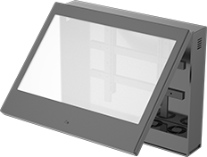 | 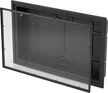 |
ABS | Polyethylene |
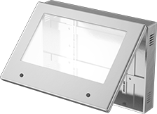 | |
Stainless Steel |
Monitor Enclosures | Tilt Brackets | ||||||||||||||||
|---|---|---|---|---|---|---|---|---|---|---|---|---|---|---|---|---|---|
Cover | Number of | ||||||||||||||||
For Max. Monitor Size | Ht. | Wd. | Dp. | Environment | Attachment Style | Closure Method | Locks | Keys Included | Color | Mounting Fasteners Included | Each | Each | |||||
ABS—NEMA 12 | |||||||||||||||||
| 32" | 29" | 36" | 8" | Dusty, Oily, Wet | Hinged | Key Lock | 1 | 2 | Black | No | 7991N11 | 000000000 | 1133A4 | 000000 | ——— | ||
| 42" | 33" | 44" | 8 3/16" | Dusty, Oily, Wet | Hinged | Key Lock | 1 | 2 | Black | No | 7991N12 | 00000000 | 1133A5 | 000000 | ——— | ||
| 50" | 38 1/4" | 50" | 8 3/16" | Dusty, Oily, Wet | Hinged | Key Lock | 1 | 2 | Black | No | 7991N13 | 00000000 | 1133A5 | 000000 | ——— | ||
| 52" | 45 1/2" | 55" | 8 3/16" | Dusty, Oily, Wet | Hinged | Key Lock | 1 | 2 | Black | No | 7991N14 | 00000000 | 1133A5 | 000000 | ——— | ||
| 65" | 48 1/4" | 65 1/2" | 8 3/16" | Dusty, Oily, Wet | Hinged | Key Lock | 1 | 2 | Black | No | 7991N15 | 00000000 | 1133A5 | 000000 | ——— | ||
Polyethylene—IP55, NEMA 4 | |||||||||||||||||
| 32" | 22" | 34 1/4" | 4 7/8" | Dusty, Outdoor, Washdown, Wet | Lift Off | Screw | — | — | Black | No | 7991N17 | 000000 | 1133A4 | 00000 | ——— | ||
| 43" | 27 1/8" | 42 1/4" | 7" | Dusty, Outdoor, Washdown, Wet | Lift Off | Screw | — | — | Black | No | 7991N18 | 000000 | 1133A5 | 000000 | ——— | ||
| 50" | 31 3/8" | 49 1/2" | 6 13/16" | Dusty, Outdoor, Washdown, Wet | Lift Off | Screw | — | — | Black | No | 7991N19 | 000000 | 1133A5 | 000000 | ——— | ||
| 55" | 35" | 55 3/8" | 6 7/8" | Dusty, Outdoor, Washdown, Wet | Lift Off | Screw | — | — | Black | No | 7991N21 | 00000000 | 1133A5 | 000000 | ——— | ||
| 65" | 40 1/8" | 64 3/8" | 6 7/8" | Dusty, Outdoor, Washdown, Wet | Lift Off | Screw | — | — | Black | No | 7991N22 | 00000000 | 1133A5 | 000000 | ——— | ||
Stainless Steel—IP66, NEMA 4X | |||||||||||||||||
| 24" | 19" | 27" | 5" | Corrosive, Dusty, Outdoor, Washdown, Wet | Hinged | Key Lock | 1 | 1 | — | No | 7991N23 | 00000000 | ——— | 000000 | 7991N28 | ||
| 32" | 24 1/2" | 36 1/2" | 6" | Corrosive, Dusty, Outdoor, Washdown, Wet | Hinged | Key Lock | 2 | 1 | — | No | 7991N24 | 00000000 | ——— | 000000 | 7991N28 | ||
| 50" | 33" | 50" | 6" | Corrosive, Dusty, Outdoor, Washdown, Wet | Hinged | Key Lock | 2 | 1 | — | No | 7991N25 | 00000000 | ——— | 000000 | 7991N28 | ||
| 55" | 35 1/2" | 56 1/2" | 6" | Corrosive, Dusty, Outdoor, Washdown, Wet | Hinged | Key Lock | 2 | 1 | — | No | 7991N26 | 00000000 | ——— | 000000 | 7991N28 | ||
| 65" | 41" | 65" | 6" | Corrosive, Dusty, Outdoor, Washdown, Wet | Hinged | Key Lock | 2 | 1 | — | No | 7991N27 | 00000000 | ——— | 000000 | 7991N28 | ||
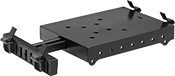
Portable Desks
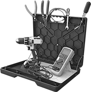 |
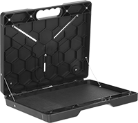 | 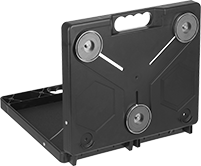 | 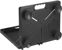 |
Back View with Magnets | Back View with Suction Cups |
Inside | |||||||||||||||||||
|---|---|---|---|---|---|---|---|---|---|---|---|---|---|---|---|---|---|---|---|
For Min. Material Thk. | Wd. | Dp. | Ht. | Wd. | Dp. | Ht. | Wt. Cap., lb. | Work Surface Style | Mounting Location | Mount Type | Mounting Hardware Included | Assembly | Features | Includes | Color | Each | |||
Portable | |||||||||||||||||||
ABS | |||||||||||||||||||
| 1/16" | 17" | 2 3/4" | 14" | 16 3/4" | 3/4" | 11 3/4" | 40 | Flat | Bench Top, Wall | Magnet, Suction Cup | Yes | Assembled | Magnetic Strips, Wire Rope Cables | Rubber Pad | Black | 5426N11 | 0000000 | ||
Wall-Mount Monitor Stands
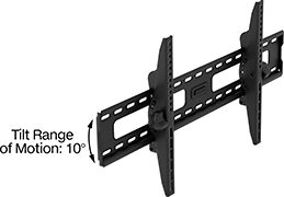 | 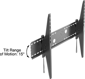 |
10° Tilt Range of Motion | 15° Tilt Range of Motion |
Overall | |||||||||||||
|---|---|---|---|---|---|---|---|---|---|---|---|---|---|
For Monitor Size (Diag.) Range | Tilt Range of Motion | Max. Load Cap., lb. | Ht. | Wd. | Material | Color | Attaching End Mounting Pattern Compatibility | Mounting Fasteners Included | Certification | Each | |||
Up and Down | |||||||||||||
| 26" to 55" | 10° | 165 | 17 5/16" | 18 1/8" | Powder-Coated Steel | Black | VESA 200 × 200, VESA 200 × 300, VESA 200 × 400, VESA 300 × 200, VESA 300 × 300, VESA 300 × 400, VESA 400 × 200, VESA 400 × 300, VESA 400 × 400 | Yes | — | 5565N111 | 000000 | ||
| 45" to 85" | 10° | 200 | 17 5/16" | 33 7/8" | Powder-Coated Steel | Black | VESA 200 × 200, VESA 200 × 300, VESA 200 × 400, VESA 300 × 200, VESA 300 × 300, VESA 300 × 400, VESA 400 × 200, VESA 400 × 300, VESA 400 × 400, VESA 500 × 300, VESA 500 × 400, VESA 600 × 300, VESA 600 × 400, VESA 800 × 300, VESA 800 × 400 | Yes | — | 5565N112 | 000000 | ||
| 60" to 100" | 15° | 350 | 32 3/4" | 44 7/8" | Powder-Coated Steel | Black | VESA 100 × 100, VESA 100 × 200, VESA 200 × 100, VESA 200 × 200, VESA 200 × 300, VESA 200 × 400, VESA 200 × 500, VESA 300 × 200, VESA 300 × 300, VESA 300 × 400, VESA 300 × 500, VESA 300 × 600, VESA 300 × 700, VESA 300 × 800, VESA 400 × 200, VESA 400 × 300, VESA 400 × 400, VESA 400 × 500, VESA 400 × 600, VESA 400 × 700, VESA 400 × 800, VESA 500 × 200, VESA 500 × 300, VESA 500 × 400, VESA 500 × 500, VESA 500 × 600, VESA 500 × 700, VESA 500 × 800, VESA 600 × 300, VESA 600 × 400, VESA 600 × 500, VESA 600 × 600, VESA 600 × 700, VESA 600 × 800, VESA 600 × 900, VESA 700 × 300, VESA 700 × 400, VESA 700 × 500, VESA 700 × 600, VESA 700 × 700, VESA 700 × 800, VESA 800 × 300, VESA 800 × 400, VESA 800 × 500, VESA 800 × 600, VESA 800 × 700, VESA 800 × 800, VESA 900 × 400, VESA 900 × 500, VESA 900 × 600, VESA 900 × 700, VESA 900 × 800, VESA 1000 × 400, VESA 1000 × 500, VESA 1000 × 600, VESA 1000 × 700, VESA 1000 × 800 | Yes | UL Listed | 5565N113 | 000000 | ||
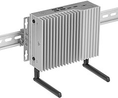
Rugged Computers
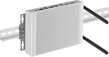 | 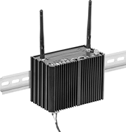 |
Intel Pentium J6426 Shown Mounted on DIN Rail | Intel Atom X6425E Shown Mounted on DIN Rail |
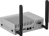
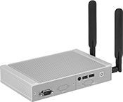 | 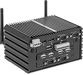 |
Intel Pentium J6426 | Intel Atom X6425E |
Connection Type | Memory Size, GB | Digital Storage Size, GB | Operating System | Temp. Range, ° F | Lg. | Wd. | Ht. | Includes | Certification | Mil. Spec. | Each | |||
|---|---|---|---|---|---|---|---|---|---|---|---|---|---|---|
Intel Pentium J6426 | ||||||||||||||
| Standard DisplayPort 1.4 (3 each) USB-A 3.2 Gen 2 (3 each) USB-A 2.0 (3 each) Ethernet RJ45 (2 each) DB9 COM (1 each) 3.5 mm Audio Input/Output (1 each) Wi-Fi 802.11b/a/g/n/ac Bluetooth 5.1 | 8 | 256 | Windows 10 IoT Enterprise LTSC 2021 | 32 to 120 | 7 3/4" | 4 3/4" | 1 1/2" | DIN-Rail Mounting Bracket, Surface Mounting Bracket, Power Adapter | CE Marked | — | 8142N13 | 000000000 | ||
Intel Atom X6425E | ||||||||||||||
| Standard DisplayPort 1.4 (3 each) USB-A 3.2 Gen 2 (3 each) USB-A 2.0 (5 each) Ethernet RJ45 (2 each) DB9 COM (4 each) 3.5 mm Audio Input (1 each) 3.5 mm Audio Output (1 each) Digital Inputs (4 each) Digital Outputs (4 each) Wi-Fi 802.11b/a/g/n/ac Bluetooth 4.2 | 16 | 256 | Windows 10 IoT Enterprise LTSC 2021 | -40 to 155 | 5 7/8" | 4 1/8" | 3 1/4" | DIN-Rail Mounting Bracket, Surface Mounting Bracket, Power Adapter | CE Marked, Mil. Spec. | MIL-STD-810 | 8142N11 | 00000000 | ||
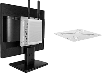 |  |
For Computers with Pentium J6426 and Intel Core i5-1250PE | For Computers with Atom X6425E |
 |  |
Intel Core i5-1250PE Shown Mounted on DIN Rail | Intel Core i5-1250PE |
Connection Type | Memory Size, GB | Digital Storage Size, GB | Operating System | Temp. Range, ° F | Lg. | Wd. | Ht. | Includes | Certification | Each | |||
|---|---|---|---|---|---|---|---|---|---|---|---|---|---|
Intel Core i5-1250PE | |||||||||||||
| Standard DisplayPort 1.4 (2 each) USB-A 3.2 Gen 2 (4 each) Ethernet RJ45 (2 each) DB9 COM (1 each) Thunderbolt 4 (2 each) Wi-Fi 802.11b/a/g/n/ac Bluetooth 5.1 | 16 | 512 | Windows 10 IoT Enterprise LTSC 2021 | 32 to 120 | 6 1/4" | 4 7/8" | 2" | DIN-Rail Mounting Bracket, Surface Mounting Bracket, Power Adapter | UL Listed, CE Marked | 8079N11 | 000000000 | ||
|
For Computers with Pentium J6426 and Intel Core i5-1250PE |
For Processor | Mounting | ||||||||
|---|---|---|---|---|---|---|---|---|---|
Manufacturer | Model No. | Pattern Compatibility | Fasteners Included | Lg. | Wd. | Material | Each | ||
| Intel | Core i5-1250PE | VESA 75 × 75, VESA 100 × 100 | Yes | 7 11/16" | 7 1/4" | Steel | 8079N12 | 000000 | |
