


Filter by
Mount Type
Mounting Location
Manufacturer Model Number
For Stylus Stem Material
Material
DFARS Specialty Metals
Export Control Classification Number (ECCN)
Probe Measurement Type
For Stylus Overall Length
Fixturing for Parts Inspection
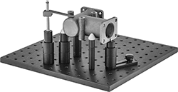 |
From towers and brackets to standoffs and supports, these components are the building blocks for your custom fixturing setup. They elevate parts so you can access a variety of angles for measuring and inspecting while protecting your measuring device from hitting the inspection table. You’ll often see them used with coordinate measuring machines (CMMs). They’re not for use in machining applications.
Kits
 |
No. of Pieces | Includes | Each | |||
|---|---|---|---|---|---|
1/4"-20 Threads | |||||
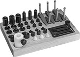
| 43 | 3 Hold-Down Clamps—1 9/16" Reach × 3" O'all Ht. 3 Hold-Down Clamps—2 5/16" Reach × 3" O'all Ht. 3 Standoffs—1/2" Dia. × 3/4" Ht. 3 Standoffs—1/2" Dia. × 2" Ht. 3 Standoffs—3/4" Dia. × 3/4" Ht. 3 Standoffs—3/4" Dia. × 2" Ht. 6 Standoffs—1/2" Dia. × 1" Ht. 6 Standoffs—3/4" Dia. × 1" Ht. 3 Pin Supports—1/2" Dia. × 1/2" Ht. 3 Pin Supports—3/4" Dia. × 1/2" Ht. 3 Cone Supports 1 Adjustable-Height Sleeve for Standoffs 2 Positioning Plates 1 Wood Stand | 1355N85 | 0000000 | ||
| 63 | 3 Hold-Down Clamps—1 9/16" Reach × 3" O'all Ht. 3 Hold-Down Clamps—2 5/16" Reach × 3" O'all Ht. 2 Toggle Clamps with Mounting Plate 3 Standoffs—1/2" Dia. × 3/4" Ht. 3 Standoffs—1/2" Dia. × 2" Ht. 3 Standoffs—3/4" Dia. × 3/4" Ht. 3 Standoffs—3/4" Dia. × 2" Ht. 3 Standoffs—1" Dia. × 3/4" Ht. 3 Standoffs—1" Dia. × 2" Ht. 6 Standoffs—1/2" Dia. × 1" Ht. 6 Standoffs—3/4" Dia. × 1" Ht. 6 Standoffs—1" Dia. × 1" Ht. 1 Precision Adjustable-Height Standoff—1/2" Dia. 3 Pin Supports—1/2" Dia. × 1/2" Ht. 3 Pin Supports—3/4" Dia. × 1/2" Ht. 6 Cone Supports 2 Any-Angle Cone Supports 1 Adjustable-Height Sleeve for Standoffs 2 Positioning Plates 1 Wood Stand | 1355N95 | 00000000 | ||
M6 Threads | |||||
| 42 | 2 Hold-Down Clamps—38 mm Reach × 38 mm O'all Ht. 4 Hold-Down Clamps—58 mm Reach × 75 mm O'all Ht. 3 Standoffs—13 mm Dia. × 20 mm Ht. 3 Standoffs—13 mm Dia. × 25 mm Ht. 3 Standoffs—13 mm Dia. × 50 mm Ht. 3 Standoffs—19 mm Dia. × 20 mm Ht. 3 Standoffs—19 mm Dia. × 25 mm Ht. 3 Standoffs—19 mm Dia. × 50 mm Ht. 3 Standoffs—25 mm Dia. × 20 mm Ht. 3 Standoffs—25 mm Dia. × 25 mm Ht. 3 Standoffs—25 mm Dia. × 50 mm Ht. 1 Adjustable-Height Standoff—13 mm Dia. 2 Pin Supports—13 mm Dia. × 25 mm Ht. 3 Cone Supports 1 Positioning Plate—35 mm Lg. 1 Positioning Plate—76 mm Lg. 1 Acetal Plastic Tray | 1409N51 | 000000 | ||
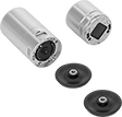
Modular Coordinate Measurement Machine Probes
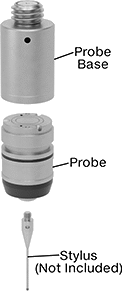 |
Probe Base and Probe Sold Separately |
Swap out Renishaw probe styles to inspect different features on a part without having to recalibrate. These probes mount magnetically to a base that threads into your coordinate measuring machine (CMM), making mid-inspection changes quick. They’re also known as modules. It’s easy to tell different styles apart from their different end colors. To take 3D measurements, they record the coordinates of different points on your workpiece. Because this involves physically touching your workpiece, they’re more accurate than other automated measurement systems. They’re touch-trigger probes, the most common CMM probe type, which means they stop to record the coordinates of one point at a time. Use them to check distances, diameters, right angles, and the location of holes and grooves. However, they're not as good at checking complex features, flatness, or roundness.
All probes require a stylus as well as a base (sold separately for some probes).
Trigger force is the amount of force required for a probe to take a measurement and record it. Choose a probe with a force that is high enough to avoid false triggers from vibration but not so high it damages the workpiece and leads to inaccurate measurements.
Probe and Base Kits
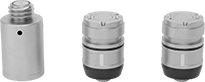 |
SF Series—SF series probes have a trigger force that works for most general purpose probing jobs where vibration is not an issue.
TP20 Series—TP20 probe bases have a magnetic proximity switch to prevent a probe from accidentally triggering when you’re attaching it or detaching it. However, probes attached to these bases can’t be used to inspect magnetic parts.
For Stylus | Trigger Force, N | |||||||||||||
|---|---|---|---|---|---|---|---|---|---|---|---|---|---|---|
No. of Pieces | Includes | Dia., mm | Thread Size | O'all Lg., mm | For Axis Measuring Direction | X- and Y-Axis | Z-Axis | End Color | Features | Manufacturer (Series) | Each | |||
| 3 | Two 20 mm Lg. SF Probes One 19 mm Lg. TP20 Probe Base | 13 | M2 | 10 to 50 | ±X, ±Y, +Z | 0.08 | 0.75 | Black | Magnetic Proximity Switch | Renishaw (SF, TP20) | 6179N11 | 000000000 | ||
 |
For Probe Mfr. Series | Mfr. | Mfr. Model No. | Each | ||
|---|---|---|---|---|---|
| TP20, TP20 NI | Renishaw | A-1042-1486 | 6179N23 | 000000 |
Probe Break Stem Installation Kits
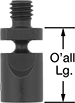 | 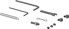 |
Probe break stem installation kits include all the components needed to properly align and replace the break stem on a tool-setting probe. Probe break stems are designed to snap if your probe applies too much pressure on a workpiece, shielding the probe from damage.
Material | |||||||||||
|---|---|---|---|---|---|---|---|---|---|---|---|
No. of Pieces | Includes | Overall Lg., mm | Stem Dia., mm | Stem | Body | Mfr. | Mfr. Model No. | Each | |||
M4 × 0.7 mm | |||||||||||
| 11 | One Break Stem One Support Bar One Captive Link Two L-Keys One Wrench Five Screws | 15.2 | 3.9 | Stainless Steel | Stainless Steel | Renishaw | A-5003-5171 | 85175A569 | 000000 | ||
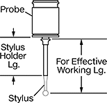
Modular Scanning Coordinate Measurement Machine Probes
Probe and Base Kits
 |  |
For Stylus | ||||||||||
|---|---|---|---|---|---|---|---|---|---|---|
No. of Pieces | Includes | For Effective Working Lg., mm | Thread Size | O'all Lg., mm | For Axis Measuring Direction | Manufacturer (Series) | Each | |||
| 4 | One SM25-1 Probe Two SH25-1 Stylus Holders One SP25M Probe Base | 20 to 50 | M3 | 20 to 50 | ±X, ±Y, ±Z | Renishaw (SM25-1, SH25-1, SP25M) | 6191N11 | 0000000000 | ||
