McMaster-Carr logo
    Filter by
    System of Measurement
    American Wire Gauge (AWG)
    Industrial Info Compare
    Attribute Image
    Number of Wires
    Attribute Image
    Outer Jacket Color
    Wire Construction
    Industrial Info Snippet
    Shielding
    Industrial Info Snippet
    Connection End Type
    Wire Material
    Cable Designation
    U.S.–Mexico–Canada Agreement (USMCA) Qualifying
    Industrial Info Compare
    Export Control Classification Number (ECCN)

    Industrial Info Snippet
    DFARS Specialty Metals
    Enter e-mail addresses in the fields below
    Message
    Cancel
    Comments
    E-mail address (if you would like a response)
    86 Products

    Vehicle Cable

    Image of Product. Front orientation. Vehicle Cable.
    Also known as GPT cable, this cable is often used in low-voltage applications such as battery and vehicle wiring and radios. It has one red wire and one black wire to easily identify polarity. The wires can be pulled apart for installation.
    Outer
    Jacket
    Per Ft.
    AWG
    No. of
    Wires
    Cable
    AWG
    Wd.
    Thk.
    Material
    Color
    Temp. Range,
    ° F
    Cable
    Designation
    Choose a Length, ft.
    1-249
    250-Up
    Stranded Wire
     
    12V DC
    24
    224/2
    0.11"0.06"PVC
    Black, Red-40 to 175GPT
    25, 50, 100, 250, 5009697T10000000000
    22
    222/2
    0.16"0.07"PVC
    Black, Red-40 to 175GPT
    25, 50, 100, 250, 5009697T7100000000
    20
    220/2
    0.17"0.08"PVC
    Black, Red-40 to 175GPT
    25, 50, 100, 250, 5009697T7200000000
    18
    218/2
    0.21"0.1"PVC
    Black, Red-40 to 175GPT
    25, 50, 100, 250, 5009697T200000000
    16
    216/2
    0.24"0.12"PVC
    Black, Red-40 to 175GPT
    25, 50, 100, 250, 5009697T7300000000
    14
    214/2
    0.29"0.15"PVC
    Black, Red-40 to 175GPT
    25, 50, 100, 250, 5009697T300000000
    12
    212/2
    0.33"0.16"PVC
    Black, Red-40 to 175GPT
    25, 50, 100, 250, 5009697T400000000
    10
    210/2
    0.4"0.2"PVC
    Black, Red-40 to 175GPT
    10, 25, 50, 100, 2509697T500000000
    8
    28/2
    0.49"0.25"PVC
    Black, Red-40 to 175GPT
    10, 25, 50, 100, 2509697T600000000
    6
    26/2
    0.69"0.32"PVC
    Black, Red-40 to 175GPT
    10, 25, 50, 100, 2509697T7400000000
    4
    24/20.89"0.43"PVC
    Black, Red-40 to 175GPT
    10, 25, 50, 1009697T7500000000
    2
    22/2
    0.97"0.45"PVC
    Black, Red-40 to 175GPT
    10, 25, 50, 1009697T7600000000
     

    Barrel DC Power Cords

    Carry DC power in or out of electronic devices with these cords. All have industry standard barrel-style connections, so you can power electronics from power supplies. Link together multiple cords to carry electricity over long distances.
    Cords
    Image of Product. Front orientation. Power Cords. Barrel DC Power Cords, Cords.
    Plug,
    mm
    Socket, mm
    Outer
    Jacket
    Lg.,
    ft.
    End
    OD
    End
    ID
    For Plug
    End OD
    For Plug
    End ID
    Voltage,
    V DC
    Current,
    amp
    Material
    Color
    Each
    Barrel Plug × Socket
    65.52.15.52.1127PVC
    Black6888N10100000
    65.52.55.52.5127PVC
    Black6888N1020000
     
    Splitters
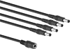
    Image of Product. Front orientation. Power Cords. Barrel DC Power Cords, Splitters.
    Send DC power to multiple electronics from a single source. The industry standard barrel-style connections make these splitters compatible with many power supplies and other devices.
    Socket
    Plug
    Outer
    Jacket
    Lg.
    For Plug
    End OD, mm
    For Plug
    End ID, mm
    No. of
    Outlets
    End OD,
    mm
    End ID,
    mm
    No. of
    Plugs
    Voltage,
    V DC
    Current,
    amp
    Material
    Color
    Each
    Barrel Socket × Plugs
    12"5.52.115.52.12128PVC
    Black6889N20100000
    16"5.52.115.52.14128PVC
    Black6889N2020000
     

    USB Chargers

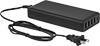
    Image of Product. Front orientation. USB Chargers. USB Chargers, Style 10.
    Image of Product. Front orientation. USB Chargers. USB Chargers, Style 12.

    Style 10

    Style 12

    Image of Specification. NEMA 1-15 Plug. Front orientation. NEMA 1-15. USB Chargers.

    NEMA

    1-15

    Plug

    Power up mobile devices and other electronics.
    Unlike many chargers in the market, these are high quality and reliable. All have passed strict U.S., Canadian, or European Union safety standards. Some of these chargers even have an LPS output, so if something fails inside the charger, it limits the risk of electrical shock. Most of our wall chargers also meet standards for energy efficiency when they're in-use, as well as when they're plugged in but not charging. Chargers that use switching regulation produce the stated voltage despite fluctuations in your outlet’s power and the power being drawn by your device. It also means they won’t get too hot.
    Straight Blade NEMA 1-15 Plug
    Image of Product. Front orientation. USB Chargers. USB Chargers, Style 10.
    Image of Specification. NEMA 1-15 Plug. Front orientation. NEMA 1-15. USB Chargers.

    Style 10

    NEMA

    1-15

    Plug

    USB-C—USB-C chargers are quickly becoming the new standard, often seen on new phones and tablets. Some are USB-C Power Delivery 3.0 certified, so they charge your devices on average 3-4 times faster than standard chargers because they send more power over your cable. 18W chargers will power phones and tablets sold after 2016. 27W chargers will power small laptops. Choose chargers with an output greater than 27W to charge large laptops and other high-power devices.
    USB-A—USB-A chargers have the traditional USB connection. 5W chargers are typically used with small electronic devices such as speakers, routers, and cameras. 10.5W chargers are typically used with phones and tablets sold before 2016. 18W chargers will power phones and tablets sold after 2016. To charge large laptops and other high-power devices, use chargers with an output greater than 27W.
    Cannot Be Sold To—Chargers cannot be sold to the listed areas due to energy efficiency regulations.
    Output
    Style
    Connection (No.
    of Ports)
    Power
    Voltage
    Input Voltage,
    V AC
    Cord Lg.,
    ft.
    Features
    Certification
    Cannot Be
    Sold To
    Each
    10USB-C (1)
    USB-A (4)
    86 W
    12 W
    5V DC, 9V DC, 12V DC, 15V DC, 20V DC
    5V DC
    100 to 2404USB-C Power Delivery 3.0UL Listed, C-UL Listed
    Canada7499N230000000
    Vehicle Plug
    Image of Product. Front orientation. USB Chargers. USB Chargers, Style 12.

    Style 12

    USB-A—USB-A chargers have the traditional USB connection. 5W chargers are typically used with small electronic devices such as speakers, routers, and cameras. 10.5W chargers are typically used with phones and tablets sold before 2016. 18W chargers will power phones and tablets sold after 2016. To charge large laptops and other high-power devices, use chargers with an output greater than 27W.
    USB-C—USB-C chargers are quickly becoming the new standard, often seen on new phones and tablets. Some are USB-C Power Delivery 3.0 certified, so they charge your devices on average 3-4 times faster than standard chargers because they send more power over your cable. 18W chargers will power phones and tablets sold after 2016. 27W chargers will power small laptops. Choose chargers with an output greater than 27W to charge large laptops and other high-power devices.
    Output
    Style
    Connection (No.
    of Ports)
    Power
    Voltage
    Voltage,
    V DC
    Cord Lg.,
    ft.
    Certification
    Each
    12USB-A (1)
    USB-C (1)
    12 W
    18 W
    5V DC
    5V DC, 9V DC, 12V DC
    126CE Marked
    7499N15000000

    DC to AC Inverter Cords

    Image of Product. With One Outlet. Front orientation. Inverters. DC to AC Inverter Cords, Total of 1 Outlets.
    Image of Product. With Two Outlets and One USB-A Port. Front orientation. Inverters. DC to AC Inverter Cords, Total of 2 Outlets, USB-A.

    With One Outlet

    With Two Outlets and One USB-A Port

    Image of Product. With Two Outlets, One USB-A Port, and One USB-C Port. Front orientation. Inverters. DC to AC Inverter Cords, Total of 2 Outlets, USB-A, USB-C.
    Image of Specification. NEMA 5-15 Outlet. Front orientation. 5-15. DC to AC Inverter Cords.

    With Two Outlets, One USB-A Port, and

    One USB-C Port

    NEMA

    5-15

    Outlet

    Plug these cords into a vehicle socket to charge devices that run on AC voltage. Also known as converters, they prevent damage from overloads.
    Vehicle
    Connection
    Straight-Blade Connection
    USB Connection
    Body
    Color
    Total No.
    of Outlets
    Input Voltage,
    V DC
    End
    Shape
    NEMA
    Type
    Output Voltage,
    V AC
    Max. Output
    Power, W
    End
    Shape
    Max. Output Current,
    amp
    Type (No.
    of Ports)
    End
    Shape
    Lg.,
    ft.
    Ht.
    Wd.
    Dp.
    Includes
    Body
    Cord
    Each
    112Straight5-15
    120150Straight3 1/21 3/4"3 3/4"5 3/4"RedBlack6987K35000000
    212Straight5-15
    120400Straight2.4
    3
    USB-A (1)
    USB-C (1)
    Straight32 1/2"5 3/4"7"Battery Cable with Alligator ClipsBlack/YellowBlack6987K2400000
    212Straight5-15
    120425Straight2.1USB-A (1)Straight22 5/8"5"6 1/2"Battery Cable with Alligator ClipsYellow/WhiteYellow6987K3600000

    Vehicle Extension Cords

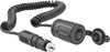
    Image of Product. Front orientation. Extension Cords. Vehicle Extension Cords.
    Power equipment directly from your vehicle when AC power or a generator isn’t available. These cords can run lights, diagnostic tools, pumps, small compressors, and other low-voltage devices during field work. They extend so you can use equipment away from your vehicle, then retract for storage. Designed for the outdoors, they have a weather‑resistant cable and a watertight cap to keep out moisture when not in use.
    Lg.,
    ft.
    AWG
    Current,
    amp
    For Use
    Outdoors
    Retracted
    Lg.
    Each
    12V DC
     
    Black
    618
    10Yes14"6860K3000000
     

    Power Cords for Solar Panel Chargers

    Image of Product. Front orientation. Power Cords. Power Cords for Solar Panel Chargers.
    Connect a flexible solar panel charger to a vehicle outlet to charge the vehicle’s battery.
    Manufacturer
    Name
    Model
    No.
    Voltage,
    V DC
    Lg.,
    ft.
    Each
    Vehicle Plug × Weather Pack Socket
    PowerFilmRA-11254859T14000000
     

    Fusible Link Wire

    Image of Product. Side1 orientation. Vehicle Wire. Fusible Link Wire.
    Often found in older vehicles, this fusible link wire protects a circuit in applications where you can’t use a standard fuse. The conductor in the fusible link melts if there’s a short circuit or voltage spike, breaking the circuit to protect the rest of your wiring. Since the conductor needs to be thin enough to melt before the rest of your wiring overheats, choose a fusible link wire that’s four gauge sizes smaller than your circuit. If you’re replacing a fusible link that has burned out, make sure the new wire is the same length and gauge as the old one.
    Cross-Linked Polyethylene Outer Jacket—Made of cross-linked polyethylene, the jacket withstands high temperatures and contains any sparks or flames caused by current overload.
    AWG
    Wire Strand
    Count
    OD
    Max. Temp.,
    ° F
    Specs.
    Met
    Outer Jacket
    Color
    Lg.,
    ft.
    Each
    Stranded Wire with Cross-Linked Polyethylene Outer Jacket
     
    12V DC
    18
    19/23
    0.02"300SAE J1128Blue86316N14500000
    18
    19/23
    0.02"300SAE J1128Blue1006316N24800000
    16
    19/30
    0.04"300SAE J1128Black76316N1540000
    16
    19/30
    0.04"300SAE J1128Black1006316N25800000
    14
    19/280.08"300SAE J1128Gray66316N1630000
    14
    19/280.08"300SAE J1128Gray1006316N268000000
    12
    19/25
    0.12"300SAE J1128Blue46316N1720000
    12
    19/25
    0.12"300SAE J1128Blue1006316N278000000
    10
    16/180.2"300SAE J1128Red16316N1810000
    10
    16/180.2"300SAE J1128Red756316N287000000
     

    Adhesive-Mount Heat Sheets

    Stick these flexible heat sheets to container surfaces to warm contents without direct contact. They require a temperature switch or controller (not included) to regulate heat output.
    Note: Do not cut, crease, or overlap these sheets—this will damage the heating element. Use a roller during installation to remove air pockets and ensure direct surface contact. Once these sheets have been applied to a surface, they cannot be removed and reused.
    Rectangle
    Image of ProductInUse. Front orientation. Heating Pads. Adhesive-Mount Heat Sheets, Rectangle.
    5 W/in² Watt Density—Sheets with a watt density of 5 watts per square inch are good for general purpose heating.
    Adhesive Back—Adhesive-back sheets have a pressure-sensitive adhesive.
    Adhesive Ready—Adhesive-ready sheets have a plain back and should be installed with Dow Corning 736 silicone sealant (not included).
    Overall
    Adhesive Back
    Adhesive Ready
    Lg.
    Wd.
    Thk.
    Wattage,
    W
    Voltage,
    V DC
    Electrical
    Phase
    Current,
    amp
    Max. Heat
    Output, ° F
    Material
    Environment
    Temp. Range, ° F
    Wire Lead
    Lg.
    For Surface Material
    Each
    Each
    5 W/in² Watt Density
    1"2"0.056"1012Single0.8390Silicone Rubber
    -40 to 30012"Metal———07945T171000000
    1"2"0.07"1012Single0.8490Silicone Rubber
    -70 to 45012"Fiberglass, Metal, Plastic7945T42000000———0
    1"3"0.056"1512Single1.3390Silicone Rubber
    -40 to 30012"Metal———07945T18100000
    1"3"0.07"1512Single1.3490Silicone Rubber
    -70 to 45012"Fiberglass, Metal, Plastic7945T4300000———0
    1"4"0.056"2012Single1.7355Silicone Rubber
    -40 to 30012"Metal7945T38100000———0
    1"4"0.056"2012Single1.7390Silicone Rubber
    -40 to 30012"Metal———07945T37100000
    1"5"0.056"2512Single2.1390Silicone Rubber
    -40 to 30012"Metal———07945T19100000
    1"5"0.07"2512Single2.1490Silicone Rubber
    -70 to 45012"Fiberglass, Metal, Plastic7945T4400000———0
    1"6"0.056"3012Single2.5355Silicone Rubber
    -40 to 30012"Metal7945T47100000———0
    1"6"0.056"3012Single2.5390Silicone Rubber
    -40 to 30012"Metal———07945T39100000
    2"5"0.056"5012Single4.2390Silicone Rubber
    -40 to 30012"Metal———07945T28100000
    2"5"0.07"5012Single4.2490Silicone Rubber
    -70 to 45012"Fiberglass, Metal, Plastic7945T4500000———0
    2"6"0.056"6012Single5390Silicone Rubber
    -40 to 30012"Metal———07945T29100000
    2"6"0.07"6012Single5490Silicone Rubber
    -70 to 45012"Fiberglass, Metal, Plastic7945T4600000———0
    3"5"0.056"7512Single6.3355Silicone Rubber
    -40 to 30012"Metal7945T74100000———0
    3"5"0.056"7512Single6.3390Silicone Rubber
    -40 to 30012"Metal———07945T73100000
    3"6"0.056"9012Single7.5355Silicone Rubber
    -40 to 30012"Metal7945T76100000———0
    3"6"0.056"9012Single7.5390Silicone Rubber
    -40 to 30012"Metal———07945T75100000
    3"9"0.056"13512Single11.3355Silicone Rubber
    -40 to 30012"Metal7945T78100000———0
    3"9"0.056"13512Single11.3390Silicone Rubber
    -40 to 30012"Metal———07945T77100000
    4"5"0.056"10012Single8.3355Silicone Rubber
    -40 to 30012"Metal7945T87100000———0
    4"5"0.056"10012Single8.3390Silicone Rubber
    -40 to 30012"Metal———07945T86100000
    4"6"0.056"12012Single10355Silicone Rubber
    -40 to 30012"Metal7945T89100000———0
    4"6"0.056"12012Single10390Silicone Rubber
    -40 to 30012"Metal———07945T88100000
     
    Square
    Image of ProductInUse. Front orientation. Heating Pads. Adhesive-Mount Heat Sheets, Square.
    5 W/in² Watt Density—Sheets with a watt density of 5 watts per square inch are good for general purpose heating.
    Adhesive Back—Adhesive-back sheets have a pressure-sensitive adhesive.
    Adhesive Ready—Adhesive-ready sheets have a plain back and should be installed with Dow Corning 736 silicone sealant (not included).
    Overall
    Adhesive Back
    Adhesive Ready
    Lg.
    Wd.
    Thk.
    Wattage,
    W
    Voltage,
    V DC
    Electrical
    Phase
    Current,
    amp
    Max. Heat
    Output, ° F
    Material
    Environment
    Temp. Range, ° F
    Wire Lead
    Lg.
    For Surface Material
    Each
    Each
    5 W/in² Watt Density
    2"2"0.056"2012Single1.7390Silicone Rubber
    -40 to 30012"Metal———07945T271000000
    2"2"0.07"2012Single1.7490Silicone Rubber
    -70 to 45012"Fiberglass, Metal, Plastic7945T41000000———0
    3"3"0.056"4512Single3.8355Silicone Rubber
    -40 to 30012"Metal7945T72100000———0
    3"3"0.056"4512Single3.8390Silicone Rubber
    -40 to 30012"Metal———07945T71100000
    4"4"0.056"8012Single6.7355Silicone Rubber
    -40 to 30012"Metal7945T85100000———0
    4"4"0.056"8012Single6.7390Silicone Rubber
    -40 to 30012"Metal———07945T84100000
    6"6"0.056"18012Single15355Silicone Rubber
    -40 to 30012"Metal7945T941000000———0
    6"6"0.056"18012Single15390Silicone Rubber
    -40 to 30012"Metal———07945T93100000
     

    Barrel DC Connectors

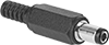
    Made with industry standard barrel-style ends, these connectors carry DC power between electronic devices and power supplies.
    Plugs
    Image of Product. Front orientation. Power Connectors. Barrel DC Connectors, Plugs.
    End OD,
    mm
    End ID,
    mm
    Voltage,
    V DC
    Current,
    amp
    Wire
    Connection
    Color
    Each
    3.51.3125SolderBlack8320N12500000
    5.52.1125SolderBlack8320N1260000
    5.52.5125SolderBlack8320N1270000

    Circuit Board Audio Equipment Connectors

    Add a spot on your circuit board for plugging in headphones and other audio equipment. To install these connectors, push their contacts through the holes in your circuit board, then solder them in place.
    90° Elbow Receptacles
    Image of Product. Back orientation. Audio Connectors. Circuit Board Audio Equipment Connectors, 90° Elbow Receptacles.
    Off (Normally Open) Circuit Position—Connectors with an off (normally open) circuit position turn equipment on when a device is plugged in.
    On (Normally Closed) Circuit Position—Connectors with an on (normally closed) circuit position turn equipment off when a device is plugged in.
    Audio Connection
    Channel
    For Pin
    Dia., mm
    No. of
    Poles
    Voltage,
    V DC
    Current,
    amp
    Color
    Housing
    Material
    Lg.
    Wd.
    Ht.
    Temp. Range,
    ° F
    Features
    Each
    Off (Normally Open) Circuit Position
    Stereo3.53121BlackPlastic0.55"0.45"0.24"0 to 145Clear Cover5734N1300000
     
    On (Normally Closed) Circuit Position
    Mono3.52121BlackPlastic0.55"0.45"0.24"0 to 145Clear Cover5734N110000
    Stereo3.53121BlackPlastic0.55"0.45"0.24"0 to 145Clear Cover5734N120000
     

    Vibration-Resistant Barrel DC Connectors

    Screw together these connectors to prevent power loss caused by vibration or accidental disconnection. The barrel-style ends are the industry standard for carrying DC power between electronic devices and power supplies.
    Panel-Mount Female Receptacles
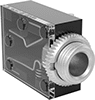
    Image of Product. Front orientation. Power Connectors. Vibration-Resistant Barrel DC Connectors, Panel-Mount Female Receptacles.
    For Plug
    End OD, mm
    For Plug
    End ID, mm
    Circuit Position
    Voltage,
    V DC
    Current,
    amp
    Wire
    Connection
    Color
    Each
    3.51.3Off (Normally Open)125SolderBlack8320N13300000
    5.52.1Off (Normally Open)125SolderBlack8320N1280000
    5.52.1On (Normally Closed)125SolderBlack8320N1290000
    5.52.5Off (Normally Open)125SolderBlack8320N1310000
    5.52.5On (Normally Closed)125SolderBlack8320N1320000

    Ultra-Flexible Constant-Wattage Heating Tape for Pipes and Tubes

    Image of ProductInUse. Front orientation. Heating Tape. Ultra-Flexible Constant-Wattage Heating Tape for Pipes and Tubes, Hardwire.

    Hardwire

    Image of Product. Top orientation. Heating Tape. Ultra-Flexible Constant-Wattage Heating Tape for Pipes and Tubes, Barrel Connection, Plug In.

    Plug In

    Barrel Connection

    Image of Specification. Closeup View of 2.1 mm ID Barrel Connector. Front orientation. ZoomedIn view. Contains Inset. Heating Tape. Ultra-Flexible Constant-Wattage Heating Tape for Pipes and Tubes, Barrel Connection, Plug In.

    Closeup View of

    2.1 mm ID Barrel

    Connector

    Wrap the flexible heating element around small-diameter pipes and tubes or pack it into tight spaces. These heaters maintain a consistent heat output along the entire length of the cable, regardless of the environmental temperature. All require a temperature switch or controller to regulate heat output. They do not produce an electromagnetic field, so they can be used near electronics.
    Note: Only install these heaters in accessible locations; do not install them behind walls, underground, or in other difficult-to-access areas. Use fiberglass tape or heat-transfer putty to install them directly on surfaces that are free of dirt, grease, and rough edges. Do not use electrical tape, duct tape, metal bands, or wire. To prevent heat loss and protect heaters from moisture and corrosion, wrap them with fiberglass insulation.
    2.1 mm Plug End ID—Pair heaters with a 2.1 mm ID barrel connector with an AC adapter (not included) to power them from a standard AC wall outlet.
    Tape
    Adapters
    Lg.,
    ft.
    Wattage,
    W
    Watt Density,
    W/ft
    Current,
    amp
    Wd.
    Thk.
    Environment
    Temp. Range, ° F
    Cable Cover
    Material
    For Surface
    Material
    Each
    Each
    Hardwire
     
    12V DC
    1330.30.12"0.06"-30 to 220Polymer FiberMetal, Plastic2156T12000000———0
    2630.50.12"0.06"-30 to 220Polymer FiberMetal, Plastic2156T2200000———0
    3930.80.12"0.06"-30 to 220Polymer FiberMetal, Plastic2156T3200000———0
    412310.12"0.06"-30 to 220Polymer FiberMetal, Plastic2156T4200000———0
     
    Plug In—2.1 mm Barrel
     
    12V DC
    1330.30.12"0.06"-30 to 220Polymer FiberMetal, Plastic2156T170000070235K4900000
    2630.50.12"0.06"-30 to 220Polymer FiberMetal, Plastic2156T210000070235K490000
    3930.80.12"0.06"-30 to 220Polymer FiberMetal, Plastic2156T310000070235K960000
    412310.12"0.06"-30 to 220Polymer FiberMetal, Plastic2156T410000070235K960000
     
    back to top