


Filter by
Display Type
Maximum Counts per Minute
Output Relay Current @ Input Voltage
Resettable
Input Voltage
Maximum Temperature
Electrical Connection
Operating Voltage
Export Control Classification Number (ECCN)
DFARS Specialty Metals
Minimum Temperature
Counters with Proximity Sensor
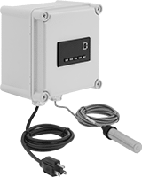 |
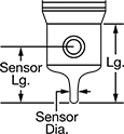
Count metallic objects as they touch or pass within 0.059" of this counter's built-in sensor. It has an output relay to send a signal to another device when a set point is reached. The signal can start/stop a process or trigger an alarm. A scaling function lets you adjust the unit of measure to suit your application. Counter and enclosure are protected from dust and washdowns and can be used outdoors (rated NEMA 4X). Drill through the back of the enclosure to mount to a wall or work surface.
Sensor | Overall | ||||||||||||||||||||||||||||||||||||||||||||||||||||||||||||||||||||||||||||||||||||||||||||||||||
|---|---|---|---|---|---|---|---|---|---|---|---|---|---|---|---|---|---|---|---|---|---|---|---|---|---|---|---|---|---|---|---|---|---|---|---|---|---|---|---|---|---|---|---|---|---|---|---|---|---|---|---|---|---|---|---|---|---|---|---|---|---|---|---|---|---|---|---|---|---|---|---|---|---|---|---|---|---|---|---|---|---|---|---|---|---|---|---|---|---|---|---|---|---|---|---|---|---|---|---|
Resettable | Counting Direction | No. of Digits | No. of Set Points | Max. Counts per min. | Max. Sensing Distance | Lg. | Dia. | Cord Lg., ft. | Ht. | Wd. | Dp. | Operating Voltage, V AC | Output Relay Current @ Input Voltage | Features | Enclosure Rating | Certification | Housing Material | Each | |||||||||||||||||||||||||||||||||||||||||||||||||||||||||||||||||||||||||||||||||
Screw On | |||||||||||||||||||||||||||||||||||||||||||||||||||||||||||||||||||||||||||||||||||||||||||||||||||
| Yes | Down, Up | 6 | 2 | 300,000 | 0.059" | 3 1/2" | 3/4" | 10 | 7.5" | 7.5" | 5.1" | 85 to 250 | 5 amp @ 120V AC 5 amp @ 240V AC 5 amp @ 28V DC | Scaling Function | NEMA 4X | UL Listed, C-UL Listed | Plastic | 00000000 | 000000000 | ||||||||||||||||||||||||||||||||||||||||||||||||||||||||||||||||||||||||||||||||
Flow and Temperature Transmitters
 |
Variable Area Flow Measurement |
 |
Vortex Flow Measurement |
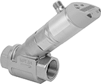
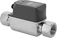
Send flow rate and temperature measurements simultaneously to a programmable logic controller (PLC), data logger, or other receiving device. Used to monitor status or control equipment, these transmitters, also known as transducers, convert measurements to an electrical signal that is interpreted by receiving devices. As flow or temperature increases, the output signal increases. For your receiving device to interpret the signal, you will need to calibrate it for the measurement range and output signal of the transmitter. They only give accurate readings within the rated measurement range. Mount them inline with your pipe system. They’ll measure flow correctly in any mounting orientation.
A digital display makes it easy to view readings and adjust settings at the source. To change settings and receive error messages remotely from your PLC or computer, program one of the outputs to use IO Link. You’ll need an IO Link controller (not included) to connect to your interface.
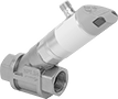
Variable Area Flow Measurement—Variable-area transmitters determine the flow rate by tracking where the liquid pushes the piston. They have two configurable outputs. One can be wired as an analog output or a digital switch. The other one can be wired as a digital switch, digital pulse output, or IO Link. Pulse outputs send flow data using spikes of voltage that match the input voltage of the transmitter. The higher the flow, the more pulses they send. These transmitters are calibrated with water, glycol solutions, and coolants but can be recalibrated in the field for other liquids.
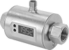
Vortex Flow Measurement—Vortex transmitters determine the flow rate by measuring the size of the vortex created as liquid flows through them. They don’t have any moving parts that can break or get stuck. Use them only with liquids that are at least 95% water. They have one analog output for flow and another for temperature. The output for temperature can also be wired for IO Link.
Flow Measurement Type | Pipe Connections | Flow Range, gph | End-to-End Lg. | Accuracy | Max. Pressure @ Temp. | Temp. Range, ° F | Seal Material | Input Voltage Range, V DC | Mounting Position | Field Recalibratable | Enclosure Rating | Each | |||||||||||||||||||||||||||||||||||||||||||||||||||||||||||||||||||||||||||||||||||||||
|---|---|---|---|---|---|---|---|---|---|---|---|---|---|---|---|---|---|---|---|---|---|---|---|---|---|---|---|---|---|---|---|---|---|---|---|---|---|---|---|---|---|---|---|---|---|---|---|---|---|---|---|---|---|---|---|---|---|---|---|---|---|---|---|---|---|---|---|---|---|---|---|---|---|---|---|---|---|---|---|---|---|---|---|---|---|---|---|---|---|---|---|---|---|---|---|---|---|---|---|
One Digital Switch/Pulse Output and One 4-20 mA Analog Transmitter/Digital Switch Output—4-Pole M12 Connection Plug | |||||||||||||||||||||||||||||||||||||||||||||||||||||||||||||||||||||||||||||||||||||||||||||||||||
316 Stainless Steel Body with 316 Stainless Steel Fitting | |||||||||||||||||||||||||||||||||||||||||||||||||||||||||||||||||||||||||||||||||||||||||||||||||||
| Variable Area | 3/4 NPT Female | 5 to 240 | 5 9/16" | ±5% | 580 psi @ 70° F | 14 to 212 | Fluoroelastomer | 18 to 30 | Any Angle | Yes | IP65, IP67 | 0000000 | 0000000 | ||||||||||||||||||||||||||||||||||||||||||||||||||||||||||||||||||||||||||||||||||||||
| Variable Area | 3/4 NPT Female | 7 to 360 | 5 9/16" | ±5% | 580 psi @ 70° F | 14 to 212 | Fluoroelastomer | 18 to 30 | Any Angle | Yes | IP65, IP67 | 0000000 | 000000 | ||||||||||||||||||||||||||||||||||||||||||||||||||||||||||||||||||||||||||||||||||||||
| Variable Area | 3/4 NPT Female | 10 to 600 | 5 9/16" | ±5% | 580 psi @ 70° F | 14 to 212 | Fluoroelastomer | 18 to 30 | Any Angle | Yes | IP65, IP67 | 0000000 | 000000 | ||||||||||||||||||||||||||||||||||||||||||||||||||||||||||||||||||||||||||||||||||||||
| Variable Area | 1 NPT Female | 30 to 1,620 | 5 3/4" | ±5% | 362 psi @ 70° F | 14 to 212 | Fluoroelastomer | 18 to 30 | Any Angle | Yes | IP65, IP67 | 0000000 | 000000 | ||||||||||||||||||||||||||||||||||||||||||||||||||||||||||||||||||||||||||||||||||||||
| Variable Area | 1 1/2 NPT Female | 60 to 3,000 | 6 3/16" | ±5% | 362 psi @ 70° F | 14 to 212 | Fluoroelastomer | 18 to 30 | Any Angle | Yes | IP65, IP67 | 0000000 | 000000 | ||||||||||||||||||||||||||||||||||||||||||||||||||||||||||||||||||||||||||||||||||||||
Two 4-20 mA Analog Transmitter Outputs—4-Pole M12 Connection Plugs | |||||||||||||||||||||||||||||||||||||||||||||||||||||||||||||||||||||||||||||||||||||||||||||||||||
316 Stainless Steel Body with 316 Stainless Steel Fitting | |||||||||||||||||||||||||||||||||||||||||||||||||||||||||||||||||||||||||||||||||||||||||||||||||||
| Vortex | 1/2 NPT Female | 16 to 317 | 4 11/16" | ±2% | 172 psi @ 70° F | 14 to 190 | Fluoroelastomer | 18 to 30 | Any Angle | No | IP65, IP67 | 0000000 | 000000 | ||||||||||||||||||||||||||||||||||||||||||||||||||||||||||||||||||||||||||||||||||||||
| Vortex | 1/2 NPT Female | 32 to 634 | 4 11/16" | ±2% | 172 psi @ 70° F | 14 to 190 | Fluoroelastomer | 18 to 30 | Any Angle | No | IP65, IP67 | 0000000 | 000000 | ||||||||||||||||||||||||||||||||||||||||||||||||||||||||||||||||||||||||||||||||||||||
| Vortex | 3/4 NPT Female | 80 to 1,585 | 5 15/32" | ±2% | 172 psi @ 70° F | 14 to 190 | Fluoroelastomer | 18 to 30 | Any Angle | No | IP65, IP67 | 0000000 | 000000 | ||||||||||||||||||||||||||||||||||||||||||||||||||||||||||||||||||||||||||||||||||||||
Build-Your-Own Flanged Pipe Flow Transmitters
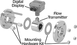 |
Components Sold Separately (Pipe Flanges Not Included) |
Flow Transmitters
 |
Flange | |||||||||||||||||||||||||||||||||||||||||||||||||||||||||||||||||||||||||||||||||||||||||||||||||||
|---|---|---|---|---|---|---|---|---|---|---|---|---|---|---|---|---|---|---|---|---|---|---|---|---|---|---|---|---|---|---|---|---|---|---|---|---|---|---|---|---|---|---|---|---|---|---|---|---|---|---|---|---|---|---|---|---|---|---|---|---|---|---|---|---|---|---|---|---|---|---|---|---|---|---|---|---|---|---|---|---|---|---|---|---|---|---|---|---|---|---|---|---|---|---|---|---|---|---|---|
Flow Measurement Type | Pipe Size | Flow Range, gpm | Bore Size | OD | Type | For Flange ANSI Class | End-to-End Lg. | Accuracy | Max. Pressure @ Temp. | Temp. Range, ° F | Mounting Position | Field Recalibratable | Pulse Frequency per Volume, pulse per gal. | Each | |||||||||||||||||||||||||||||||||||||||||||||||||||||||||||||||||||||||||||||||||||||
One Digital Pulse Output—2-Pin BNC Connection Plug | |||||||||||||||||||||||||||||||||||||||||||||||||||||||||||||||||||||||||||||||||||||||||||||||||||
316/316L Stainless Steel Body with 316/316L Stainless Steel Fitting | |||||||||||||||||||||||||||||||||||||||||||||||||||||||||||||||||||||||||||||||||||||||||||||||||||
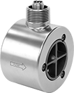
| Turbine | 1 | 3 to 30 | 7/8" | 2" | Round | 150 | 4" | ±1.0% | 285 psi @ 70° F | -150 to 350 | Any Angle | No | 3,100 | 0000000 | 0000000 | ||||||||||||||||||||||||||||||||||||||||||||||||||||||||||||||||||||||||||||||||||||
| Turbine | 2 | 5 to 50 | 1" | 3 5/8" | Round | 150 | 2 1/2" | ±1.0% | 285 psi @ 70° F | -150 to 350 | Any Angle | No | 850 | 0000000 | 00000000 | ||||||||||||||||||||||||||||||||||||||||||||||||||||||||||||||||||||||||||||||||||||
| Turbine | 2 | 15 to 180 | 1 1/2" | 3 5/8" | Round | 150 | 2 1/2" | ±1.0% | 285 psi @ 70° F | -150 to 350 | Any Angle | No | 325 | 0000000 | 00000000 | ||||||||||||||||||||||||||||||||||||||||||||||||||||||||||||||||||||||||||||||||||||
| Turbine | 3 | 60 to 600 | 3" | 5" | Round | 150 | 4 1/4" | ±1.0% | 285 psi @ 70° F | -150 to 350 | Any Angle | No | 50 | 0000000 | 00000000 | ||||||||||||||||||||||||||||||||||||||||||||||||||||||||||||||||||||||||||||||||||||
 |
For Pipe Size | For Bore Size | For Flange ANSI Class | Includes | Each | ||
|---|---|---|---|---|---|---|
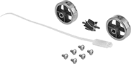
| 1 | 7/8" | 150 | 6 Screws, 2 Rotor Supports, One Rotor Assembly, One K-Factor Tag | 0000000 | 0000000 | |
| 2 | 1" | 150 | 6 Screws, 2 Rotor Supports, One Rotor Assembly, One K-Factor Tag | 0000000 | 000000 | |
| 2 | 1 1/2" | 150 | 6 Screws, 2 Rotor Supports, One Rotor Assembly, One K-Factor Tag | 0000000 | 000000 | |
| 3 | 3" | 150 | 6 Screws, 2 Rotor Supports, One Rotor Assembly, One K-Factor Tag | 0000000 | 00000000 |
Compact Rotary Encoders
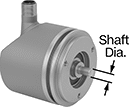
Incremental Optical Encoders with Shaft
 |
5-Pole Micro M12 Plug-In Connection—IO Link |
Incremental transmitters track how much a rotating shaft has turned relative to a reference point. They need to be reset after a power loss.
Transmitters with a shaft connect to a motor’s shaft with a flexible shaft coupling to fit different diameters.
IO Link Communication Protocol—Transmitters with IO link let you set their resolution remotely when connected to a PLC, a human-machine interface (HMI), or a computer.
IP65 Enclosure Rating—IP-rated transmitters are protected from dust and water.
Encoders | Connectors | ||||||||||||||||||||||||||||||||||||||||||||||||||||||||||||||||||||||||||||||||||||||||||||||||||
|---|---|---|---|---|---|---|---|---|---|---|---|---|---|---|---|---|---|---|---|---|---|---|---|---|---|---|---|---|---|---|---|---|---|---|---|---|---|---|---|---|---|---|---|---|---|---|---|---|---|---|---|---|---|---|---|---|---|---|---|---|---|---|---|---|---|---|---|---|---|---|---|---|---|---|---|---|---|---|---|---|---|---|---|---|---|---|---|---|---|---|---|---|---|---|---|---|---|---|---|
Mounting Holes | |||||||||||||||||||||||||||||||||||||||||||||||||||||||||||||||||||||||||||||||||||||||||||||||||||
Shaft Dia., mm | Rotary Encoder Type | Input Voltage, V DC | Max. Input Current, mA | Output Current, mA | For Max. Shaft Speed, rpm | Body Material | Housing Material | Enclosure Rating | No. of | Thread Size | Fasteners Included | Resolution | Each | Each | |||||||||||||||||||||||||||||||||||||||||||||||||||||||||||||||||||||||||||||||||||||
5-Pole Micro M12 Plug-In Connection—IO Link | |||||||||||||||||||||||||||||||||||||||||||||||||||||||||||||||||||||||||||||||||||||||||||||||||||
| 6 | Single Turn | 5 to 30 | 150 | 50 | 12,000 | Stainless Steel | Aluminum | IP65 | 3 | M4 × 0.7 mm | No | 1 to 10,000 | 00000000 | 0000000 | 0000000 | 000000 | |||||||||||||||||||||||||||||||||||||||||||||||||||||||||||||||||||||||||||||||||||
| 10 | Single Turn | 5 to 30 | 150 | 50 | 12,000 | Stainless Steel | Aluminum | IP65 | 3 | M4 × 0.7 mm | No | 1 to 10,000 | 00000000 | 000000 | 0000000 | 00000 | |||||||||||||||||||||||||||||||||||||||||||||||||||||||||||||||||||||||||||||||||||
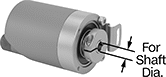
Incremental Optical Encoders with Shaft Opening
 |
5-Pole Micro M12 Plug-In Connection—IO Link |
Incremental transmitters track how much a rotating shaft has turned relative to a reference point. They need to be reset after a power loss.
Transmitters with a shaft opening slide onto your motor's shaft. Their mounting plate flexes to compensate for your motor's vibration.
IO Link Communication Protocol—Transmitters with IO link let you set their resolution remotely when connected to a PLC, a human-machine interface (HMI), or a computer.
IP65 Enclosure Rating—IP-rated transmitters are protected from dust and water.
Encoders | Connectors | ||||||||||||||||||||||||||||||||||||||||||||||||||||||||||||||||||||||||||||||||||||||||||||||||||
|---|---|---|---|---|---|---|---|---|---|---|---|---|---|---|---|---|---|---|---|---|---|---|---|---|---|---|---|---|---|---|---|---|---|---|---|---|---|---|---|---|---|---|---|---|---|---|---|---|---|---|---|---|---|---|---|---|---|---|---|---|---|---|---|---|---|---|---|---|---|---|---|---|---|---|---|---|---|---|---|---|---|---|---|---|---|---|---|---|---|---|---|---|---|---|---|---|---|---|---|
Mounting Holes | |||||||||||||||||||||||||||||||||||||||||||||||||||||||||||||||||||||||||||||||||||||||||||||||||||
For Shaft Dia., mm | Rotary Encoder Type | Input Voltage, V DC | Max. Input Current, mA | Output Current, mA | For Max. Shaft Speed, rpm | Body Material | Housing Material | Enclosure Rating | Mounting Plate Dia. | No. of | Thread Size | Fasteners Included | Resolution | Each | Each | ||||||||||||||||||||||||||||||||||||||||||||||||||||||||||||||||||||||||||||||||||||
5-Pole Micro M12 Plug-In Connection—IO Link | |||||||||||||||||||||||||||||||||||||||||||||||||||||||||||||||||||||||||||||||||||||||||||||||||||
| 6 | Single Turn | 5 to 30 | 150 | 50 | 12,000 | Stainless Steel | Aluminum | IP65 | 1.43" | 4 | M2.5 × 0.5 mm | No | 1 to 10,000 | 00000000 | 0000000 | 0000000 | 000000 | ||||||||||||||||||||||||||||||||||||||||||||||||||||||||||||||||||||||||||||||||||
| 10 | Single Turn | 5 to 30 | 150 | 50 | 12,000 | Stainless Steel | Aluminum | IP65 | 1.43" | 4 | M2.5 × 0.5 mm | No | 1 to 10,000 | 00000000 | 000000 | 0000000 | 00000 | ||||||||||||||||||||||||||||||||||||||||||||||||||||||||||||||||||||||||||||||||||
Absolute Optical Encoders with Shaft
|
5-Pole Micro M12 Plug-In Connection—IO Link |
Absolute transmitters give you the exact position of the shaft, even after a power loss.
Transmitters with a shaft connect to a motor’s shaft with a flexible shaft coupling to fit different diameters.
IO Link Communication Protocol—Transmitters with IO link let you set their resolution remotely when connected to a PLC, a human-machine interface (HMI), or a computer.
Multi-Turn Rotary Encoder—Multi-turn absolute transmitters count how many full turns a shaft makes. They’re often used to keep print rollers aligned over multiple rotations.
IP65 Enclosure Rating—IP-rated transmitters are protected from dust and water.
Encoders | Connectors | ||||||||||||||||||||||||||||||||||||||||||||||||||||||||||||||||||||||||||||||||||||||||||||||||||
|---|---|---|---|---|---|---|---|---|---|---|---|---|---|---|---|---|---|---|---|---|---|---|---|---|---|---|---|---|---|---|---|---|---|---|---|---|---|---|---|---|---|---|---|---|---|---|---|---|---|---|---|---|---|---|---|---|---|---|---|---|---|---|---|---|---|---|---|---|---|---|---|---|---|---|---|---|---|---|---|---|---|---|---|---|---|---|---|---|---|---|---|---|---|---|---|---|---|---|---|
Mounting Holes | |||||||||||||||||||||||||||||||||||||||||||||||||||||||||||||||||||||||||||||||||||||||||||||||||||
Shaft Dia., mm | Rotary Encoder Type | Input Voltage, V DC | Max. Input Current, mA | Output Current, mA | For Max. Shaft Speed, rpm | Body Material | Housing Material | Enclosure Rating | No. of | Thread Size | Fasteners Included | Bit Resolution, bit | Each | Each | |||||||||||||||||||||||||||||||||||||||||||||||||||||||||||||||||||||||||||||||||||||
5-Pole Micro M12 Plug-In Connection—IO Link | |||||||||||||||||||||||||||||||||||||||||||||||||||||||||||||||||||||||||||||||||||||||||||||||||||
| 6 | Multi-Turn | 18 to 30 | 75 | 50 | 12,000 | Stainless Steel | Aluminum | IP65 | 3 | M4 × 0.7 mm | No | 1 to 31 | 00000000 | 0000000 | 0000000 | 000000 | |||||||||||||||||||||||||||||||||||||||||||||||||||||||||||||||||||||||||||||||||||
| 10 | Multi-Turn | 18 to 30 | 75 | 50 | 12,000 | Stainless Steel | Aluminum | IP65 | 3 | M4 × 0.7 mm | No | 1 to 31 | 00000000 | 000000 | 0000000 | 00000 | |||||||||||||||||||||||||||||||||||||||||||||||||||||||||||||||||||||||||||||||||||
Printing Calculators
Business Calculator
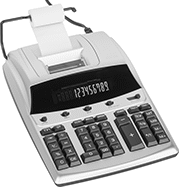 |
Cost/Sell/Margin Function—Cost/sell/margin function allows you to enter any two variables to get the third.
Calculators | Replacement Ink | Replacement Paper Rolls | |||||||||||||||
|---|---|---|---|---|---|---|---|---|---|---|---|---|---|---|---|---|---|
Face Style | Calculator Functions | No. of Digits | Lg. | Wd. | Ht. | Power Source | Electrical Connection Type | Cord Lg., ft. | Ink Color | Includes | Each | Each | Each | ||||
| Angled | Cost/Sell/Margin | 12 | 12 1/4" | 8 1/2" | 3" | Electric | Plug In | 6 | Black, Red | One Roll of Printer Paper | 0000000 | 0000000 | 0000000 | 00000 | 0000000 | 00000 | |
Flow, Pressure, and Temperature Transmitters for Gases
 |
Flow Measurement Type | Pipe Connections | Flow Range, scfm | End-to-End Lg. | Accuracy | Max. Pressure @ Temp. | Temp. Range, ° F | Seal Material | Input Voltage Range, V DC | Mounting Position | Field Recalibratable | Enclosure Rating | Each | |||||||||||||||||||||||||||||||||||||||||||||||||||||||||||||||||||||||||||||||||||||||
|---|---|---|---|---|---|---|---|---|---|---|---|---|---|---|---|---|---|---|---|---|---|---|---|---|---|---|---|---|---|---|---|---|---|---|---|---|---|---|---|---|---|---|---|---|---|---|---|---|---|---|---|---|---|---|---|---|---|---|---|---|---|---|---|---|---|---|---|---|---|---|---|---|---|---|---|---|---|---|---|---|---|---|---|---|---|---|---|---|---|---|---|---|---|---|---|---|---|---|---|
One Digital Switch/Pulse Output and One 4-20 mA Analog Transmitter/Digital Switch/Pulse Output—4-Pole M12 Connection Plug | |||||||||||||||||||||||||||||||||||||||||||||||||||||||||||||||||||||||||||||||||||||||||||||||||||
304 Stainless Steel Body with 304 Stainless Steel Fitting | |||||||||||||||||||||||||||||||||||||||||||||||||||||||||||||||||||||||||||||||||||||||||||||||||||
| Thermal | 1/2 NPT Male | 0.15 to 44 | 11 13/16" | ±6% | 230 psi @ 70° F | 14 to 140 | Fluoroelastomer | 18 to 30 | Any Angle | No | IP65, IP67 | 0000000 | 000000000 | ||||||||||||||||||||||||||||||||||||||||||||||||||||||||||||||||||||||||||||||||||||||
| Thermal | 1 NPT Male | 0.4 to 132 | 18 3/4" | ±6% | 230 psi @ 70° F | 14 to 140 | Fluoroelastomer | 18 to 30 | Any Angle | No | IP65, IP67 | 0000000 | 00000000 | ||||||||||||||||||||||||||||||||||||||||||||||||||||||||||||||||||||||||||||||||||||||
Insertion-Mount Flow and Temperature Transmitters
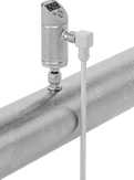 |
Thread mounting hardware (sold separately) into your pipe connection and insert the probe of these transmitters to measure the flow and temperature of water, oil, or air. The probe is held in place with a compression fitting on the other end of the mounting hardware. They’re often used in large-diameter pipes where it would be difficult to install a transmitter inline. To calculate the flow rate, these transmitters generate a small amount of heat, then measure the cooling effect your liquid or air has on it. They measure and output both flow and temperature, making them ideal for applications where temperature fluctuates. Also known as transducers, they convert measurements to an electrical signal that can be interpreted by receiving devices, such as remote displays and programmable logic controllers (PLCs) to monitor flow or control equipment. As flow or temperature increases, the output signal increases. For your receiving device to interpret the signal, you will need to calibrate it for the measurement range and output signal of the transmitter. They only give accurate readings within the rated measurement range. They’ll measure flow correctly in any mounting orientation. These transmitters are calibrated with air, glycol solutions, oil, and water but can be recalibrated in the field for other liquids.
Adjust settings at the source using the digital display. These transmitters have two configurable outputs. One can be wired for flow or temperature as an analog output or a digital switch. The other one can be wired for flow as a digital switch, digital pulse output, or IO Link. Pulse outputs send flow data using spikes of voltage that match the input voltage of the transmitter. The higher the flow, the more pulses they send. To change settings and receive error messages remotely from your PLC or computer, you can program one of the outputs to use IO Link. You’ll need an IO Link controller (not included) to connect to your interface.
Flow Measurement Type | Flow Range, gpm | Probe Lg. | End-to-End Lg. | Accuracy | Max. Pressure @ Temp. | Temp. Range, ° F | Input Voltage Range, V DC | Mounting Position | Field Recalibratable | Enclosure Rating | Each | ||||||||||||||||||||||||||||||||||||||||||||||||||||||||||||||||||||||||||||||||||||||||
|---|---|---|---|---|---|---|---|---|---|---|---|---|---|---|---|---|---|---|---|---|---|---|---|---|---|---|---|---|---|---|---|---|---|---|---|---|---|---|---|---|---|---|---|---|---|---|---|---|---|---|---|---|---|---|---|---|---|---|---|---|---|---|---|---|---|---|---|---|---|---|---|---|---|---|---|---|---|---|---|---|---|---|---|---|---|---|---|---|---|---|---|---|---|---|---|---|---|---|---|
One Digital Switch/Pulse Output and One 4-20 mA Analog Transmitter/Digital Switch/Pulse Output—4-Pole M12 Connection Plug | |||||||||||||||||||||||||||||||||||||||||||||||||||||||||||||||||||||||||||||||||||||||||||||||||||
316 Stainless Steel/Polybutylene Body with 316 Stainless Steel Fitting | |||||||||||||||||||||||||||||||||||||||||||||||||||||||||||||||||||||||||||||||||||||||||||||||||||
| Thermal | 0.02 to 12 | 3 15/16" | 7 9/16" | ±10% | 725 psi @ 212° F | 0 to 212 | 18 to 30 | Any Angle | Yes | IP65, IP67 | 00000000 | 0000000 | |||||||||||||||||||||||||||||||||||||||||||||||||||||||||||||||||||||||||||||||||||||||
| Thermal | 0.02 to 12 | 7 7/8" | 11 1/2" | ±10% | 725 psi @ 212° F | 0 to 212 | 18 to 30 | Any Angle | Yes | IP65, IP67 | 00000000 | 000000 | |||||||||||||||||||||||||||||||||||||||||||||||||||||||||||||||||||||||||||||||||||||||
Sanitary Conductivity Sensors
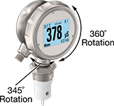 |
Three-Color Display |
 |
Often used to save rinse water in beverage and pharmaceutical lines, these sensors test the amount of chemicals, cleaners, and other substances in liquids by measuring how well the liquid conducts electricity. They’re 3-A and European Hygienic Engineering and Design Group (EHEDG) certified, thanks to their design that’s easy to keep clean. Highly polished, they limit where bacteria could grow. They also withstand washdowns with hot water, chemicals, and cleaners common to sanitary lines because of their PEEK probe, stainless steel body, and IP ratings. Their IP ratings also mean they’re dust tight and won’t fail if briefly under water. All are FDA compliant to safely touch food.
These sensors work with 4-20 mA analog output to connect to remote displays and programmable logic controllers (PLCs), making them good for hard-to-reach areas and frequent application changes. This also means they’ll set off alarms and trigger cycles to start and stop in automated systems. With the touchscreen, program each color of the display to alert you to errors, completed cycles, and other events. Both the head and the display rotate to view readings from the best angle.
Highly accurate, these sensors test almost any liquid. They also measure temperature—no need for a separate sensor. To compare readings as temperature changes, they automatically standardize readings at 77° F. All meet European safety standards, since they’re CE marked.
Cannot Be Sold To—Import regulations restrict sales to the listed areas.
Sensor | Conductivity | ||||||||||||||||||||||||||||||||||||||||||||||||||||||||||||||||||||||||||||||||||||||||||||||||||
|---|---|---|---|---|---|---|---|---|---|---|---|---|---|---|---|---|---|---|---|---|---|---|---|---|---|---|---|---|---|---|---|---|---|---|---|---|---|---|---|---|---|---|---|---|---|---|---|---|---|---|---|---|---|---|---|---|---|---|---|---|---|---|---|---|---|---|---|---|---|---|---|---|---|---|---|---|---|---|---|---|---|---|---|---|---|---|---|---|---|---|---|---|---|---|---|---|---|---|---|
Lg., mm | Material | Dia., mm | Lg., mm | Range | Accuracy | Electrical Connection Type | Pipe Size | Thread Type | Gender | ATC Range, ° F | Enclosure Rating | Certification | Food Industry Std. | Cannot Be Sold To | Each | ||||||||||||||||||||||||||||||||||||||||||||||||||||||||||||||||||||||||||||||||||||
For Use With Liquids | |||||||||||||||||||||||||||||||||||||||||||||||||||||||||||||||||||||||||||||||||||||||||||||||||||
| 37 | PEEK | 3.6 | 26 | 0 to 1,000 mS 0 to 500 mS 0 to 500 μS | ±1.5% ±1% ±1.5% | Threaded M12 Plug (Two 4-Pole Connections) | 1 | BSPP | Male | -4 to 302 | IP67, IP69K | CE Marked, EHEDG Certified | 3-A Certified 74-07, FDA Compliant 21 CFR 177.2415 | Canada | 0000000 | 000000000 | |||||||||||||||||||||||||||||||||||||||||||||||||||||||||||||||||||||||||||||||||||
| 60 | PEEK | 3.6 | 26 | 0 to 1,000 mS 0 to 500 mS 0 to 500 μS | ±1.5% ±1% ±1.5% | Threaded M12 Plug (Two 4-Pole Connections) | 1 | BSPP | Male | -4 to 302 | IP67, IP69K | CE Marked, EHEDG Certified | 3-A Certified 74-07, FDA Compliant 21 CFR 177.2415 | Canada | 0000000 | 00000000 | |||||||||||||||||||||||||||||||||||||||||||||||||||||||||||||||||||||||||||||||||||
Electric Sit-Stand Desks
 |
Dark-Gray Top |
Light-Gray Top |
White Top |
Red Woodgrain |
Switch between sitting and standing while working. Press a button on the height adjustment switch, and the electric motor raises or lowers these workstations to your desired height. Assign up to three different heights to the three program buttons—press a button to automatically adjust the desk to the programmed height. These workstations also have programmable upper and lower height limits, and a lock function to prevent accidental height changes.
Overall | Electrical | ||||||||||||||||||||||||||||||||||||||||||||||||||||||||||||||||||||||||||||||||||||||||||||||||||
|---|---|---|---|---|---|---|---|---|---|---|---|---|---|---|---|---|---|---|---|---|---|---|---|---|---|---|---|---|---|---|---|---|---|---|---|---|---|---|---|---|---|---|---|---|---|---|---|---|---|---|---|---|---|---|---|---|---|---|---|---|---|---|---|---|---|---|---|---|---|---|---|---|---|---|---|---|---|---|---|---|---|---|---|---|---|---|---|---|---|---|---|---|---|---|---|---|---|---|---|
Top Color | Frame Color | Wd. | Dp. | Ht. | Overall Wt. Cap., lb. | Elevation Speed, in/sec | Assembly | Connection | No. of Blades | Power Cord Lg., ft. | Each | ||||||||||||||||||||||||||||||||||||||||||||||||||||||||||||||||||||||||||||||||||||||||
Laminate Top with Powder-Coated Steel Frame | |||||||||||||||||||||||||||||||||||||||||||||||||||||||||||||||||||||||||||||||||||||||||||||||||||
| Dark Gray | Silver | 48" | 30" | 27 1/2" to 47" | 125 | 1 1/2 | Unassembled | Straight Blade | 2 | 10 | 00000000 | 0000000 | |||||||||||||||||||||||||||||||||||||||||||||||||||||||||||||||||||||||||||||||||||||||
| Light Gray | Silver | 48" | 30" | 27 1/2" to 47" | 125 | 1 1/2 | Unassembled | Straight Blade | 2 | 10 | 00000000 | 000000 | |||||||||||||||||||||||||||||||||||||||||||||||||||||||||||||||||||||||||||||||||||||||
| White | Silver | 48" | 30" | 27 1/2" to 47" | 125 | 1 1/2 | Unassembled | Straight Blade | 2 | 10 | 00000000 | 000000 | |||||||||||||||||||||||||||||||||||||||||||||||||||||||||||||||||||||||||||||||||||||||
| Red Woodgrain | Black | 48" | 30" | 27 1/2" to 47" | 125 | 1 1/2 | Unassembled | Straight Blade | 2 | 10 | 00000000 | 000000 | |||||||||||||||||||||||||||||||||||||||||||||||||||||||||||||||||||||||||||||||||||||||
Flow Transmitters
 |
Variable Area Flow Measurement |
Send flow rate measurements to monitor and control equipment. Also known as transducers, these transmitters convert flow rate measurements to an electrical signal that can be interpreted by receiving devices, such as remote displays and programmable logic controllers (PLCs). As flow increases, the output signal increases. For your receiving device to interpret the signal, you will need to calibrate it for the measurement range and output signal of the transmitter. They only give accurate readings within the rated measurement range. Mount them directly inline with your system. They measure flow correctly no matter their mounting orientation.
These transmitters are calibrated with water. You can use them with other liquids, but they may not measure accurately if the liquid’s viscosity differs from water.
Variable Area Flow Measurement—Variable-area transmitters determine flow rate by tracking where the liquid pushes an internal piston.
Flow Measurement Type | Pipe Connections | Flow Range, gpm | End-to-End Lg. | Accuracy | Max. Pressure @ Temp. | Temp. Range, ° F | Seal Material | Input Voltage Range, V DC | Mounting Position | Field Recalibratable | Enclosure Rating | Each | |||||||||||||||||||||||||||||||||||||||||||||||||||||||||||||||||||||||||||||||||||||||
|---|---|---|---|---|---|---|---|---|---|---|---|---|---|---|---|---|---|---|---|---|---|---|---|---|---|---|---|---|---|---|---|---|---|---|---|---|---|---|---|---|---|---|---|---|---|---|---|---|---|---|---|---|---|---|---|---|---|---|---|---|---|---|---|---|---|---|---|---|---|---|---|---|---|---|---|---|---|---|---|---|---|---|---|---|---|---|---|---|---|---|---|---|---|---|---|---|---|---|---|
One 4-20 mA Analog Transmitter Output—4-Pole M12 Connection Plug | |||||||||||||||||||||||||||||||||||||||||||||||||||||||||||||||||||||||||||||||||||||||||||||||||||
316L Stainless Steel/Aluminum/Brass/Plastic Body with 316 Stainless Steel/Brass Fitting | |||||||||||||||||||||||||||||||||||||||||||||||||||||||||||||||||||||||||||||||||||||||||||||||||||
| Variable Area | 1 NPT Female | 0.5 to 27 | 3 5/8" | ±5% | 362 psi @ 212° F | 14 to 212 | Fluoroelastomer | 18 to 32 | Any Angle | No | IP65, IP67 | 00000000 | 0000000 | ||||||||||||||||||||||||||||||||||||||||||||||||||||||||||||||||||||||||||||||||||||||
Two 4-20 mA Analog Transmitter Outputs—4-Pole M12 Connection Plugs | |||||||||||||||||||||||||||||||||||||||||||||||||||||||||||||||||||||||||||||||||||||||||||||||||||
316L Stainless Steel/Aluminum/Brass/Plastic Body with 316 Stainless Steel/Brass Fitting | |||||||||||||||||||||||||||||||||||||||||||||||||||||||||||||||||||||||||||||||||||||||||||||||||||
| Variable Area | 3/4 NPT Female | 0.1 to 4 | 2 15/16" | ±5% | 580 psi @ 212° F | 14 to 212 | Fluoroelastomer | 18 to 30 | Any Angle | No | IP65, IP67 | 00000000 | 000000 | ||||||||||||||||||||||||||||||||||||||||||||||||||||||||||||||||||||||||||||||||||||||
| Variable Area | 3/4 NPT Female | 0.1 to 6 | 2 15/16" | ±5% | 580 psi @ 212° F | 14 to 212 | Fluoroelastomer | 18 to 30 | Any Angle | No | IP65, IP67 | 00000000 | 000000 | ||||||||||||||||||||||||||||||||||||||||||||||||||||||||||||||||||||||||||||||||||||||
| Variable Area | 3/4 NPT Female | 0.2 to 10 | 2 15/16" | ±5% | 580 psi @ 212° F | 14 to 212 | Fluoroelastomer | 18 to 30 | Any Angle | No | IP65, IP67 | 00000000 | 000000 | ||||||||||||||||||||||||||||||||||||||||||||||||||||||||||||||||||||||||||||||||||||||
High-Accuracy Flow and Temperature Transmitters
 |
Flow Range | |||||||||||||||||||||||||||||||||||||||||||||||||||||||||||||||||||||||||||||||||||||||||||||||||||
|---|---|---|---|---|---|---|---|---|---|---|---|---|---|---|---|---|---|---|---|---|---|---|---|---|---|---|---|---|---|---|---|---|---|---|---|---|---|---|---|---|---|---|---|---|---|---|---|---|---|---|---|---|---|---|---|---|---|---|---|---|---|---|---|---|---|---|---|---|---|---|---|---|---|---|---|---|---|---|---|---|---|---|---|---|---|---|---|---|---|---|---|---|---|---|---|---|---|---|---|
Flow Measurement Type | Pipe Connections | Gallons per Minute, gpm | Liters per Minute, L/min | End-to-End Lg. | Accuracy | Max. Pressure @ Temp. | Temp. Range, ° F | Input Voltage Range, V DC | Mounting Position | Field Recalibratable | Enclosure Rating | Each | |||||||||||||||||||||||||||||||||||||||||||||||||||||||||||||||||||||||||||||||||||||||
Two 4-20 mA Analog Transmitter Outputs—4-Pole M12 Connection Plugs | |||||||||||||||||||||||||||||||||||||||||||||||||||||||||||||||||||||||||||||||||||||||||||||||||||
316 Stainless Steel/Plastic/Polybutylene Body with 316 Stainless Steel Fitting | |||||||||||||||||||||||||||||||||||||||||||||||||||||||||||||||||||||||||||||||||||||||||||||||||||
| Magnetic Induction | 1/2 NPT Female | 0.03 to 6.6 | 0.1 to 25 | 2 1/8" | ±2% | 225 psi @ 70° F | 0 to 175 | 20 to 30 | Any Angle | No | IP67 | 00000000 | 0000000 | ||||||||||||||||||||||||||||||||||||||||||||||||||||||||||||||||||||||||||||||||||||||
| Magnetic Induction | 3/4 NPT Female | 0.02 to 13.22 | 0.2 to 50 | 2 1/8" | ±2% | 225 psi @ 70° F | 0 to 175 | 20 to 30 | Any Angle | No | IP67 | 00000000 | 000000 | ||||||||||||||||||||||||||||||||||||||||||||||||||||||||||||||||||||||||||||||||||||||
| Magnetic Induction | 1 NPT Female | 0.1 to 26.4 | 0.2 to 100 | 2 1/8" | ±2% | 225 psi @ 70° F | 0 to 175 | 20 to 30 | Any Angle | No | IP67 | 00000000 | 000000 | ||||||||||||||||||||||||||||||||||||||||||||||||||||||||||||||||||||||||||||||||||||||
| Magnetic Induction | 1 1/2 NPT Female | 1.3 to 79.3 | 5 to 300 | 6 11/16" | ±0.8% | 225 psi @ 70° F | 0 to 175 | 20 to 30 | Any Angle | No | IP65, IP67 | 00000000 | 00000000 | ||||||||||||||||||||||||||||||||||||||||||||||||||||||||||||||||||||||||||||||||||||||
| Magnetic Induction | 2 NPT Female | 1.3 to 158.5 | 5 to 600 | 7 1/16" | ±0.8% | 225 psi @ 70° F | 0 to 175 | 20 to 30 | Any Angle | No | IP65, IP67 | 00000000 | 00000000 | ||||||||||||||||||||||||||||||||||||||||||||||||||||||||||||||||||||||||||||||||||||||
Linear Motion Position-Measuring Transmitters
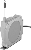 | 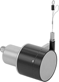 | 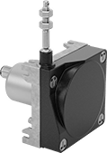 | 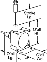 |
Style 2 | Style 3 | Style 4 | Styles 1-4 |
4-Pole M12 Plug |
5-Pole M12 Plug |
Transmitters | Cables with Socket | ||||||||||||||||||||||||||||||||||||||||||||||||||||||||||||||||||||||||||||||||||||||||||||||||||
|---|---|---|---|---|---|---|---|---|---|---|---|---|---|---|---|---|---|---|---|---|---|---|---|---|---|---|---|---|---|---|---|---|---|---|---|---|---|---|---|---|---|---|---|---|---|---|---|---|---|---|---|---|---|---|---|---|---|---|---|---|---|---|---|---|---|---|---|---|---|---|---|---|---|---|---|---|---|---|---|---|---|---|---|---|---|---|---|---|---|---|---|---|---|---|---|---|---|---|---|
Overall | Mounting Holes | ||||||||||||||||||||||||||||||||||||||||||||||||||||||||||||||||||||||||||||||||||||||||||||||||||
Stroke Lg. | Percentage Accuracy Range | Repeatability Percentage Range | Max. Input Voltage | Input Resistance, kohm | Output Signal | Housing Material | Enclosure Rating | Eyelet ID | Lg. | Wd. | Ht. | Ctr.-to-Ctr. | Dia. | No. of | Each | Each | |||||||||||||||||||||||||||||||||||||||||||||||||||||||||||||||||||||||||||||||||||
Style 2 | |||||||||||||||||||||||||||||||||||||||||||||||||||||||||||||||||||||||||||||||||||||||||||||||||||
With 4-Pole M12 Plug | |||||||||||||||||||||||||||||||||||||||||||||||||||||||||||||||||||||||||||||||||||||||||||||||||||
| 120" | -0.35% to 0.35% | -0.05% to 0.05% | 30V AC 30V DC | 10 | 0-28.2V AC 0-28.2V DC | Plastic | IP67 | 0.191" | 2.48" | 5.17" | 5.09" | (A) 4 3/4" (B) 4.62" (C) 2.2" | 7/32" 3/16" 3/16" | 6 | 00000000 | 0000000 | 0000000 | 000000 | |||||||||||||||||||||||||||||||||||||||||||||||||||||||||||||||||||||||||||||||||
Style 3 | |||||||||||||||||||||||||||||||||||||||||||||||||||||||||||||||||||||||||||||||||||||||||||||||||||
With 5-Pole M12 Plug | |||||||||||||||||||||||||||||||||||||||||||||||||||||||||||||||||||||||||||||||||||||||||||||||||||
| 75" | -0.02% to 0.02% | -0.006% to 0.006% | 32V DC | 4.8 | 4 mA to 20 mA | Steel | IP64 | 0.197" | 4.11" | 3.11" | 3.27" | (A) 0.98" | 7/32" | 2 | 00000000 | 000000 | 0000000 | 00000 | |||||||||||||||||||||||||||||||||||||||||||||||||||||||||||||||||||||||||||||||||
Style 4 | |||||||||||||||||||||||||||||||||||||||||||||||||||||||||||||||||||||||||||||||||||||||||||||||||||
With 5-Pole M12 Plug | |||||||||||||||||||||||||||||||||||||||||||||||||||||||||||||||||||||||||||||||||||||||||||||||||||
| 118" | -0.012% to 0.012% | -0.005% to 0.005% | 32V DC | 4.8 | 4 mA to 20 mA | Steel | IP64 | 0.083" | 3.61" | 3.07" | 3.58" | (A) 2.32" (B) 2.44" | 3/16" 3/16" | 8 | 00000000 | 000000 | 0000000 | 00000 | |||||||||||||||||||||||||||||||||||||||||||||||||||||||||||||||||||||||||||||||||
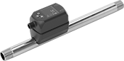
Compression Tube Flow Transmitters for Gases
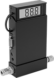 |
Commonly referred to as thermal mass flowmeters, these transmitters calculate flow rate by measuring how much they cool as air and other gases pass through them. This means they’re accurate even if there are temperature and pressure changes, unlike most other transmitters. Used to monitor flow or control equipment, these transmitters, also known as transducers, convert measurements to an electrical signal that is interpreted by receiving devices. As flow increases, the output signal increases. For your receiving device to interpret the signal, you will need to calibrate it for the measurement range and output signal of the transmitter. They only give accurate readings within the rated measurement range. A digital display makes it easy to check the flow rate and adjust settings. Mount these transmitters inline with your system.
These transmitters are calibrated with air. You can use them with other gases, but they will not be as accurate.
Adapters—Voltage adapters are required to connect these transmitters to a power source.
Flow Transmitters | Adapters | ||||||||||||||||||||||||||||||||||||||||||||||||||||||||||||||||||||||||||||||||||||||||||||||||||
|---|---|---|---|---|---|---|---|---|---|---|---|---|---|---|---|---|---|---|---|---|---|---|---|---|---|---|---|---|---|---|---|---|---|---|---|---|---|---|---|---|---|---|---|---|---|---|---|---|---|---|---|---|---|---|---|---|---|---|---|---|---|---|---|---|---|---|---|---|---|---|---|---|---|---|---|---|---|---|---|---|---|---|---|---|---|---|---|---|---|---|---|---|---|---|---|---|---|---|---|
For Tube OD | Flow Range, L/min | End-to-End Lg. | Accuracy | Max. Pressure @ Temp. | Temp. Range, ° F | Seal Material | Input Voltage Range, V DC | Mounting Position | Each | Each | |||||||||||||||||||||||||||||||||||||||||||||||||||||||||||||||||||||||||||||||||||||||||
One 4-20 mA Analog Transmitter Output—2.1 mm Plug End ID Barrel Connection/DB9 Connection Plug | |||||||||||||||||||||||||||||||||||||||||||||||||||||||||||||||||||||||||||||||||||||||||||||||||||
Aluminum Body with Brass Fitting | |||||||||||||||||||||||||||||||||||||||||||||||||||||||||||||||||||||||||||||||||||||||||||||||||||
| 1/4" | 0 to 0.01 | 5 1/8" | ±1.0% | 1,000 psi @ 70° F | 32 to 122 | Viton® Fluoroelastomer | 12 to 26 | Horizontal | 0000000 | 0000000 | 00000000 | 00000 | |||||||||||||||||||||||||||||||||||||||||||||||||||||||||||||||||||||||||||||||||||||||
| 1/4" | 0 to 0.05 | 5 1/8" | ±1.0% | 1,000 psi @ 70° F | 32 to 122 | Viton® Fluoroelastomer | 12 to 26 | Horizontal | 0000000 | 000000 | 00000000 | 0000 | |||||||||||||||||||||||||||||||||||||||||||||||||||||||||||||||||||||||||||||||||||||||
| 1/4" | 0 to 0.1 | 5 1/8" | ±1.0% | 1,000 psi @ 70° F | 32 to 122 | Viton® Fluoroelastomer | 12 to 26 | Horizontal | 0000000 | 000000 | 00000000 | 0000 | |||||||||||||||||||||||||||||||||||||||||||||||||||||||||||||||||||||||||||||||||||||||
| 1/4" | 0 to 0.5 | 5 1/8" | ±1.0% | 1,000 psi @ 70° F | 32 to 122 | Viton® Fluoroelastomer | 12 to 26 | Horizontal | 0000000 | 000000 | 00000000 | 0000 | |||||||||||||||||||||||||||||||||||||||||||||||||||||||||||||||||||||||||||||||||||||||
| 1/4" | 0 to 1 | 5 1/8" | ±1.0% | 1,000 psi @ 70° F | 32 to 122 | Viton® Fluoroelastomer | 12 to 26 | Horizontal | 0000000 | 000000 | 00000000 | 0000 | |||||||||||||||||||||||||||||||||||||||||||||||||||||||||||||||||||||||||||||||||||||||
| 1/4" | 0 to 5 | 5 1/8" | ±1.0% | 1,000 psi @ 70° F | 32 to 122 | Viton® Fluoroelastomer | 12 to 26 | Horizontal | 0000000 | 000000 | 00000000 | 0000 | |||||||||||||||||||||||||||||||||||||||||||||||||||||||||||||||||||||||||||||||||||||||
| 1/4" | 0 to 10 | 5 1/8" | ±1.0% | 1,000 psi @ 70° F | 32 to 122 | Viton® Fluoroelastomer | 12 to 26 | Horizontal | 0000000 | 000000 | 00000000 | 0000 | |||||||||||||||||||||||||||||||||||||||||||||||||||||||||||||||||||||||||||||||||||||||
| 1/4" | 0 to 50 | 6 3/16" | ±1.0% | 1,000 psi @ 70° F | 32 to 122 | Viton® Fluoroelastomer | 12 to 26 | Horizontal | 0000000 | 00000000 | 00000000 | 0000 | |||||||||||||||||||||||||||||||||||||||||||||||||||||||||||||||||||||||||||||||||||||||
| 3/8" | 0 to 100 | 6 1/4" | ±1.0% | 1,000 psi @ 70° F | 32 to 122 | Viton® Fluoroelastomer | 12 to 26 | Horizontal | 0000000 | 00000000 | 00000000 | 0000 | |||||||||||||||||||||||||||||||||||||||||||||||||||||||||||||||||||||||||||||||||||||||
