


Filter by
System of Measurement
Input Voltage
Counting Direction
Wire Connection
Operating Voltage
Batteries Included
Electrical Connection Type
Housing Material
Maximum Temperature
Minimum Temperature
Electrical Connection
Number of Counters
RoHS
Export Control Classification Number (ECCN)
DFARS Specialty Metals
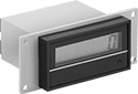
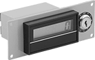
Panel-Mount Electrically Actuated Counters
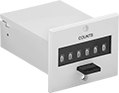 | 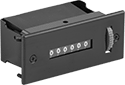 | 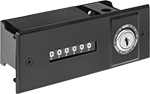 | 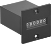 |
Screw On Style A | Screw On Style B | Screw On Style C | Screw On Style D |
 |  |  | |
Screw On Style E | Screw On Style F | Clip On Style H |
For Panel Cutout | Overall | Mounting | |||||||||||||||||||||||||||||||||||||||||||||||||||||||||||||||||||||||||||||||||||||||||||||||||
|---|---|---|---|---|---|---|---|---|---|---|---|---|---|---|---|---|---|---|---|---|---|---|---|---|---|---|---|---|---|---|---|---|---|---|---|---|---|---|---|---|---|---|---|---|---|---|---|---|---|---|---|---|---|---|---|---|---|---|---|---|---|---|---|---|---|---|---|---|---|---|---|---|---|---|---|---|---|---|---|---|---|---|---|---|---|---|---|---|---|---|---|---|---|---|---|---|---|---|---|
Style | Resettable | Counting Direction | No. of Digits | Max. Counts per min. | Ht. | Wd. | Ht. | Wd. | Dp. | Input Voltage | Features | Fasteners Included | Screw Size | Enclosure Rating | Certification | Housing Material | Each | ||||||||||||||||||||||||||||||||||||||||||||||||||||||||||||||||||||||||||||||||||
Screw On | |||||||||||||||||||||||||||||||||||||||||||||||||||||||||||||||||||||||||||||||||||||||||||||||||||
Wire Leads | |||||||||||||||||||||||||||||||||||||||||||||||||||||||||||||||||||||||||||||||||||||||||||||||||||
| A | No | Up | 6 | 600 | 1" | 2" | 1.8" | 2.2" | 2.6" | 24V DC | — | No | No. 4 | — | UL Recognized Component | Plastic | 1806T23 | 000000 | |||||||||||||||||||||||||||||||||||||||||||||||||||||||||||||||||||||||||||||||||
| A | Yes | Up | 4 | 600 | 1" | 1.5" | 1.8" | 1.8" | 2.6" | 24V DC | — | No | No. 4 | — | UL Recognized Component | Plastic | 1806T22 | 00000 | |||||||||||||||||||||||||||||||||||||||||||||||||||||||||||||||||||||||||||||||||
| A | Yes | Up | 4 | 600 | 1" | 1.5" | 1.8" | 1.8" | 2.6" | 120V AC | — | No | No. 4 | — | UL Recognized Component | Plastic | 8686T28 | 00000 | |||||||||||||||||||||||||||||||||||||||||||||||||||||||||||||||||||||||||||||||||
| A | Yes | Up | 6 | 600 | 1" | 2" | 1.8" | 2.2" | 2.6" | 12V DC | — | No | No. 4 | — | UL Recognized Component | Plastic | 1806T44 | 00000 | |||||||||||||||||||||||||||||||||||||||||||||||||||||||||||||||||||||||||||||||||
| A | Yes | Up | 6 | 600 | 1" | 2" | 1.8" | 2.2" | 2.6" | 24V DC | — | No | No. 4 | — | UL Recognized Component | Plastic | 1806T41 | 00000 | |||||||||||||||||||||||||||||||||||||||||||||||||||||||||||||||||||||||||||||||||
| A | Yes | Up | 6 | 600 | 1" | 2" | 1.8" | 2.2" | 2.6" | 120V AC | — | No | No. 4 | — | UL Recognized Component | Plastic | 8686T46 | 00000 | |||||||||||||||||||||||||||||||||||||||||||||||||||||||||||||||||||||||||||||||||
| B | Yes | Up | 6 | 1,000 | 1.8" | 3.9" | 1.9" | 4.5" | 2.3" | 120V AC | — | Yes | No. 6 | — | UL Recognized Component | Zinc Alloy | 8686T58 | 000000 | |||||||||||||||||||||||||||||||||||||||||||||||||||||||||||||||||||||||||||||||||
| C | Yes | Up | 6 | 1,000 | 1.8" | 4.9" | 2.2" | 5.6" | 2.3" | 120V AC | — | Yes | No. 6 | — | UL Recognized Component | Zinc Alloy | 8686T59 | 000000 | |||||||||||||||||||||||||||||||||||||||||||||||||||||||||||||||||||||||||||||||||
| D | No | Up | 6 | 600 | 1" | 1.5" | 1.8" | 1.8" | 2.5" | 12V DC | — | Yes | No. 4 | — | UL Recognized Component | Plastic | 1806T66 | 00000 | |||||||||||||||||||||||||||||||||||||||||||||||||||||||||||||||||||||||||||||||||
| D | No | Up | 6 | 600 | 1" | 1.5" | 1.8" | 1.8" | 2.5" | 24V DC | — | Yes | No. 4 | — | UL Recognized Component | Plastic | 1806T65 | 00000 | |||||||||||||||||||||||||||||||||||||||||||||||||||||||||||||||||||||||||||||||||
| D | No | Up | 6 | 600 | 1" | 1.5" | 1.8" | 1.8" | 2.5" | 120V AC | — | Yes | No. 6 | — | UL Recognized Component | Plastic | 1876T36 | 00000 | |||||||||||||||||||||||||||||||||||||||||||||||||||||||||||||||||||||||||||||||||
| E | Yes | Up | 6 | 2,400 | 1.8" | 3" | 1.9" | 4.5" | 2.9" | 6V AC to 240V AC, 6V DC to 240V DC | Battery-Powered Display | No | No. 8 | — | — | Zinc Alloy | 1874T82 | 000000 | |||||||||||||||||||||||||||||||||||||||||||||||||||||||||||||||||||||||||||||||||
| F | Yes | Up | 6 | 2,400 | 1.5" | 4.8" | 2.2" | 5.5" | 2.9" | 6V AC to 240V AC, 6V DC to 240V DC | Battery-Powered Display | No | No. 8 | — | — | Zinc Alloy | 1874T83 | 000000 | |||||||||||||||||||||||||||||||||||||||||||||||||||||||||||||||||||||||||||||||||
Clip On | |||||||||||||||||||||||||||||||||||||||||||||||||||||||||||||||||||||||||||||||||||||||||||||||||||
Wire Leads | |||||||||||||||||||||||||||||||||||||||||||||||||||||||||||||||||||||||||||||||||||||||||||||||||||
| H | No | Up | 7 | 600 | 0.6" | 1.2" | 0.6" | 1.3" | 1.3" | 120V AC | — | — | — | IP65 | UL Recognized Component, C-UL Recognized Component | Plastic | 1806T12 | 00000 | |||||||||||||||||||||||||||||||||||||||||||||||||||||||||||||||||||||||||||||||||
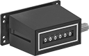
Surface-Mount Electrically Actuated Counters
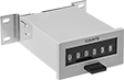 |  | 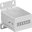 |
Screw On Style A | Screw On Style B | Screw On Style C |
 |  |  |
Screw On Style D | Screw On Style E | Screw On Style F |
Overall | Mounting | ||||||||||||||||||||||||||||||||||||||||||||||||||||||||||||||||||||||||||||||||||||||||||||||||||
|---|---|---|---|---|---|---|---|---|---|---|---|---|---|---|---|---|---|---|---|---|---|---|---|---|---|---|---|---|---|---|---|---|---|---|---|---|---|---|---|---|---|---|---|---|---|---|---|---|---|---|---|---|---|---|---|---|---|---|---|---|---|---|---|---|---|---|---|---|---|---|---|---|---|---|---|---|---|---|---|---|---|---|---|---|---|---|---|---|---|---|---|---|---|---|---|---|---|---|---|
Style | Resettable | Counting Direction | No. of Digits | Max. Counts per min. | Ht. | Wd. | Dp. | Input Voltage | Features | Fasteners Included | Screw Size | Enclosure Rating | Certification | Housing Material | Each | ||||||||||||||||||||||||||||||||||||||||||||||||||||||||||||||||||||||||||||||||||||
Screw On | |||||||||||||||||||||||||||||||||||||||||||||||||||||||||||||||||||||||||||||||||||||||||||||||||||
Wire Leads | |||||||||||||||||||||||||||||||||||||||||||||||||||||||||||||||||||||||||||||||||||||||||||||||||||
| A | Yes | Up | 4 | 600 | 1.2" | 2.6" | 2.9" | 120V AC | — | No | No. 4 | — | UL Recognized Component | Plastic | 8686T27 | 000000 | |||||||||||||||||||||||||||||||||||||||||||||||||||||||||||||||||||||||||||||||||||
| A | Yes | Up | 6 | 600 | 1.2" | 3.1" | 2.9" | 24V DC | — | No | No. 4 | — | UL Recognized Component | Plastic | 1806T42 | 00000 | |||||||||||||||||||||||||||||||||||||||||||||||||||||||||||||||||||||||||||||||||||
| A | Yes | Up | 6 | 600 | 1.2" | 3.1" | 2.9" | 120V AC | — | No | No. 4 | — | UL Recognized Component | Plastic | 8686T45 | 00000 | |||||||||||||||||||||||||||||||||||||||||||||||||||||||||||||||||||||||||||||||||||
| B | Yes | Up | 6 | 1,000 | 2.6" | 3.7" | 1.8" | 120V AC | — | No | No. 6 | — | UL Recognized Component | Zinc Alloy | 8686T57 | 000000 | |||||||||||||||||||||||||||||||||||||||||||||||||||||||||||||||||||||||||||||||||||
| C | No | Up | 6 | 600 | 2.3" | 1.7" | 2.3" | 120V AC | — | No | No. 5 | — | UL Recognized Component | Steel | 1876T38 | 00000 | |||||||||||||||||||||||||||||||||||||||||||||||||||||||||||||||||||||||||||||||||||
| C | No | Up | 6 | 600 | 2.3" | 1.8" | 2.4" | 24V DC | — | No | No. 5 | — | UL Recognized Component | Steel | 1806T79 | 00000 | |||||||||||||||||||||||||||||||||||||||||||||||||||||||||||||||||||||||||||||||||||
| D | No | Up | 7 | 600 | 1.4" | 1.6" | 1.7" | 12V DC | — | No | No. 5 | — | UL Recognized Component | Plastic | 1806T67 | 00000 | |||||||||||||||||||||||||||||||||||||||||||||||||||||||||||||||||||||||||||||||||||
| D | No | Up | 7 | 600 | 1.4" | 1.6" | 1.7" | 24V AC | — | No | No. 5 | — | UL Recognized Component | Plastic | 1876T79 | 00000 | |||||||||||||||||||||||||||||||||||||||||||||||||||||||||||||||||||||||||||||||||||
| D | No | Up | 7 | 600 | 1.4" | 1.6" | 1.7" | 120V AC | — | No | No. 5 | — | UL Recognized Component | Plastic | 1876T78 | 00000 | |||||||||||||||||||||||||||||||||||||||||||||||||||||||||||||||||||||||||||||||||||
| E | No | Up | 7 | 1,500 | 0.6" | 1.8" | 1.7" | 12V DC | — | No | No. 5 | IP65 | UL Recognized Component, C-UL Recognized Component | Plastic | 1806T14 | 00000 | |||||||||||||||||||||||||||||||||||||||||||||||||||||||||||||||||||||||||||||||||||
| E | No | Up | 7 | 1,500 | 0.6" | 1.8" | 1.7" | 24V DC | — | No | No. 5 | IP65 | UL Recognized Component, C-UL Recognized Component | Plastic | 1806T15 | 00000 | |||||||||||||||||||||||||||||||||||||||||||||||||||||||||||||||||||||||||||||||||||
| F | Yes | Up | 6 | 2,400 | 1.8" | 3.9" | 3" | 6V AC to 240V AC, 6V DC to 240V DC | Battery-Powered Display | No | No. 5 | — | — | Zinc Alloy | 1874T81 | 000000 | |||||||||||||||||||||||||||||||||||||||||||||||||||||||||||||||||||||||||||||||||||
Switch-Contact-Actuated Counters
 |
Clip On, Manual Reset Button |
Counters | Gaskets | ||||||||||||||||||||||||||||||||||||||||||||||||||||||||||||||||||||||||||||||||||||||||||||||||||
|---|---|---|---|---|---|---|---|---|---|---|---|---|---|---|---|---|---|---|---|---|---|---|---|---|---|---|---|---|---|---|---|---|---|---|---|---|---|---|---|---|---|---|---|---|---|---|---|---|---|---|---|---|---|---|---|---|---|---|---|---|---|---|---|---|---|---|---|---|---|---|---|---|---|---|---|---|---|---|---|---|---|---|---|---|---|---|---|---|---|---|---|---|---|---|---|---|---|---|---|
For Panel Cutout | Overall | ||||||||||||||||||||||||||||||||||||||||||||||||||||||||||||||||||||||||||||||||||||||||||||||||||
Resettable | Counting Direction | No. of Digits | Max. Counts per min. | DIN Size | Ht. | Wd. | Ht. | Wd. | Dp. | Batteries Replaceable | Features | Certification | Housing Material | Each | Each | ||||||||||||||||||||||||||||||||||||||||||||||||||||||||||||||||||||||||||||||||||||
Clip On | |||||||||||||||||||||||||||||||||||||||||||||||||||||||||||||||||||||||||||||||||||||||||||||||||||
Wire Leads | |||||||||||||||||||||||||||||||||||||||||||||||||||||||||||||||||||||||||||||||||||||||||||||||||||
| Yes | Up | 8 | 30,000 | 1/32 | 0.87" | 1.78" | 1.1" | 2" | 1.5" | No | Battery-Powered Display, Indicator Icons, Manual Reset Button, Remote Reset | UL Recognized Component, C-UL Recognized Component, CE Marked | Plastic | 7235N11 | 000000 | 8672T46 | 00000 | ||||||||||||||||||||||||||||||||||||||||||||||||||||||||||||||||||||||||||||||||||
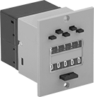
Panel-Mount Electrically Actuated Counters with Output Relay
 |
Screw On |
Wire these counters up to an electrical pulse-emitting switch, sensor, or encoder for use on machine tools, packaging machinery, or other equipment. They display the set point and count incoming pulses. When the counter reaches the set point, an output relay sends a signal to another device. The signal can start/stop a process or trigger an alarm.
For Panel Cutout | Overall | Mounting | |||||||||||||||||||||||||||||||||||||||||||||||||||||||||||||||||||||||||||||||||||||||||||||||||
|---|---|---|---|---|---|---|---|---|---|---|---|---|---|---|---|---|---|---|---|---|---|---|---|---|---|---|---|---|---|---|---|---|---|---|---|---|---|---|---|---|---|---|---|---|---|---|---|---|---|---|---|---|---|---|---|---|---|---|---|---|---|---|---|---|---|---|---|---|---|---|---|---|---|---|---|---|---|---|---|---|---|---|---|---|---|---|---|---|---|---|---|---|---|---|---|---|---|---|---|
Resettable | Counting Direction | No. of Counters | No. of Digits | No. of Set Points | Max. Counts per min. | Ht. | Wd. | Ht. | Wd. | Dp. | Input Voltage | Output Relay Current @ Input Voltage | Fasteners Included | Screw Size | Housing Material | Each | |||||||||||||||||||||||||||||||||||||||||||||||||||||||||||||||||||||||||||||||||||
Screw On | |||||||||||||||||||||||||||||||||||||||||||||||||||||||||||||||||||||||||||||||||||||||||||||||||||
Wire Leads | |||||||||||||||||||||||||||||||||||||||||||||||||||||||||||||||||||||||||||||||||||||||||||||||||||
| Yes | Up | 2 | 5 | 1 | 600 | 2" | 2" | 2.7" | 2.2" | 2.8" | 24V DC | 5 amp @ 250V AC 2 amp @ 24V DC | No | No. 4 | Plastic | 2148T18 | 0000000 | ||||||||||||||||||||||||||||||||||||||||||||||||||||||||||||||||||||||||||||||||||
| Yes | Up | 2 | 5 | 1 | 600 | 2" | 2" | 2.7" | 2.2" | 2.8" | 120V AC | 5 amp @ 250V AC 2 amp @ 24V DC | No | No. 4 | Plastic | 2148T24 | 000000 | ||||||||||||||||||||||||||||||||||||||||||||||||||||||||||||||||||||||||||||||||||
Electrically Actuated Minute Meters
 |  |
Screw On Style A | Screw On Style B |
Display running time on a machine so you can schedule preventative maintenance.
Not Resettable—Non-resettable counter prevents tampering and accidental loss of data.
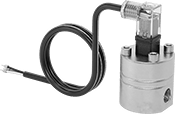
Contactless Flow Transmitters
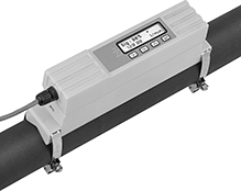 |
Using ultrasonic waves, these transmitters measure the flow rate of your liquid from outside your pipe. They're a good choice for applications where you need to retrofit your system or avoid liquid coming into contact with the transmitter. Also known as transducers, these transmitters convert measurements to an electrical pulse that can be interpreted by receiving devices, such as remote displays and programmable logic controllers (PLCs). The pulse outputs match the input voltage of the transmitter. The higher the flow, the more pulses they send. For your receiving device to interpret the signal, you will need to calibrate it for the measurement range and output signal of the transmitter. They only give accurate readings within the rated measurement range. Configure them for either a 4-20mA or digital pulse output when installing.
A digital display makes it easy to check flow rate and configure settings. Clamp these transmitters onto your pipe with the included mounting hardware and gel pads. They measure flow no matter the mounting orientation.
These transmitters are calibrated with water but can be used with other liquids and will generally measure accurately, even if they differ in viscosity and density. You can recalibrate them in the field for accurate readings on pipe and operating conditions.
Flow Range for Pipe Size, gpm | Input Voltage | ||||||||||||||||||||||||||||||||||||||||||||||||||||||||||||||||||||||||||||||||||||||||||||||||||
|---|---|---|---|---|---|---|---|---|---|---|---|---|---|---|---|---|---|---|---|---|---|---|---|---|---|---|---|---|---|---|---|---|---|---|---|---|---|---|---|---|---|---|---|---|---|---|---|---|---|---|---|---|---|---|---|---|---|---|---|---|---|---|---|---|---|---|---|---|---|---|---|---|---|---|---|---|---|---|---|---|---|---|---|---|---|---|---|---|---|---|---|---|---|---|---|---|---|---|---|
Flow Measurement Type | For Pipe Size | 3/4 | 2 | 4 | End-to-End Lg. | Accuracy | Temp. Range, ° F | Min., V DC | Max. | Mounting Position | Field Recalibratable | Enclosure Rating | Each | ||||||||||||||||||||||||||||||||||||||||||||||||||||||||||||||||||||||||||||||||||||||
One Digital Pulse Output and One 4-20 mA Analog Transmitter Output—Wire Lead Connection | |||||||||||||||||||||||||||||||||||||||||||||||||||||||||||||||||||||||||||||||||||||||||||||||||||
Polycarbonate Body | |||||||||||||||||||||||||||||||||||||||||||||||||||||||||||||||||||||||||||||||||||||||||||||||||||
| Ultrasonic | 3/4 to 4 | 0 to 45 | 0 to 320 | 0 to 1,285 | 9 3/4" | ±3% | 32 to 185 | 12 | 24V AC/24V DC | Any Angle | Yes | IP54 | 4399N11 | 000000000 | |||||||||||||||||||||||||||||||||||||||||||||||||||||||||||||||||||||||||||||||||||||
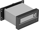
Panel-Mount Electrically Actuated Hour Meters
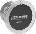 | 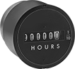 | 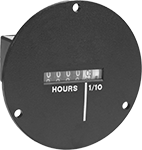 |  |
Screw On Style A | Screw On Style B | Screw On Style C | Screw On Style D |
For Panel Cutout | Overall | ||||||||||||||||||||||||||||||||||||||||||||||||||||||||||||||||||||||||||||||||||||||||||||||||||
|---|---|---|---|---|---|---|---|---|---|---|---|---|---|---|---|---|---|---|---|---|---|---|---|---|---|---|---|---|---|---|---|---|---|---|---|---|---|---|---|---|---|---|---|---|---|---|---|---|---|---|---|---|---|---|---|---|---|---|---|---|---|---|---|---|---|---|---|---|---|---|---|---|---|---|---|---|---|---|---|---|---|---|---|---|---|---|---|---|---|---|---|---|---|---|---|---|---|---|---|
Style | Resettable | Counting Direction | No. of Digits | Dia. | Wd. | Ht. | Ht. | Wd. | Dp. | Dia. | Operating Voltage | Each | |||||||||||||||||||||||||||||||||||||||||||||||||||||||||||||||||||||||||||||||||||||||
Screw On | |||||||||||||||||||||||||||||||||||||||||||||||||||||||||||||||||||||||||||||||||||||||||||||||||||
Wire Leads | |||||||||||||||||||||||||||||||||||||||||||||||||||||||||||||||||||||||||||||||||||||||||||||||||||
| A | No | Up | 6 | 2.3" | — | — | — | — | 2" | 2.9" | 24V AC | 8672T15 | 0000000 | ||||||||||||||||||||||||||||||||||||||||||||||||||||||||||||||||||||||||||||||||||||||
| A | No | Up | 6 | 2.3" | — | — | — | — | 2" | 2.9" | 120V AC | 8672T11 | 00000 | ||||||||||||||||||||||||||||||||||||||||||||||||||||||||||||||||||||||||||||||||||||||
| A | No | Up | 6 | 2.3" | — | — | — | — | 2" | 2.9" | 230V AC | 8672T12 | 00000 | ||||||||||||||||||||||||||||||||||||||||||||||||||||||||||||||||||||||||||||||||||||||
| B | No | Up | 6 | — | 2.3" | 2.3" | — | — | 2.5" | 3" | 120V AC | 1693T84 | 000000 | ||||||||||||||||||||||||||||||||||||||||||||||||||||||||||||||||||||||||||||||||||||||
| B | No | Up | 6 | 2.3" | — | — | — | — | 2.5" | 3.5" | 120V AC | 1693T26 | 00000 | ||||||||||||||||||||||||||||||||||||||||||||||||||||||||||||||||||||||||||||||||||||||
| C | No | Up | 5 | — | 1.5" | 1" | — | — | 1.9" | 2.9" | 120V AC | 1877T86 | 00000 | ||||||||||||||||||||||||||||||||||||||||||||||||||||||||||||||||||||||||||||||||||||||
| D | No | Up | 5 | — | 1.5" | 1" | 1.1" | 2.1" | 1.9" | — | 120V AC | 1877T82 | 00000 | ||||||||||||||||||||||||||||||||||||||||||||||||||||||||||||||||||||||||||||||||||||||
Flow Transmitters with Sight
 |
Flow Measurement Type | Pipe Connections | Flow Range, gpm | End-to-End Lg. | Accuracy | Max. Pressure @ Temp. | Temp. Range, ° F | Seal Material | Input Voltage Range, V DC | Mounting Position | Field Recalibratable | Pulse Freq., Hz | Pulse Frequency per Volume, pulse per gal. | Each | ||||||||||||||||||||||||||||||||||||||||||||||||||||||||||||||||||||||||||||||||||||||
|---|---|---|---|---|---|---|---|---|---|---|---|---|---|---|---|---|---|---|---|---|---|---|---|---|---|---|---|---|---|---|---|---|---|---|---|---|---|---|---|---|---|---|---|---|---|---|---|---|---|---|---|---|---|---|---|---|---|---|---|---|---|---|---|---|---|---|---|---|---|---|---|---|---|---|---|---|---|---|---|---|---|---|---|---|---|---|---|---|---|---|---|---|---|---|---|---|---|---|---|
One 4-20 mA Analog Transmitter Output—Wire Lead Connection | |||||||||||||||||||||||||||||||||||||||||||||||||||||||||||||||||||||||||||||||||||||||||||||||||||
Glass-Filled Polypropylene Body with Glass-Filled Polypropylene Fitting | |||||||||||||||||||||||||||||||||||||||||||||||||||||||||||||||||||||||||||||||||||||||||||||||||||
| Turbine | 1/2 NPT Female | 0.25 to 2.5 | 3 11/16" | ±2% | 150 psi @ 70° F | 20 to 150 | Buna-N | 12 to 24 | Any Angle | No | — | — | 9687K141 | 0000000 | |||||||||||||||||||||||||||||||||||||||||||||||||||||||||||||||||||||||||||||||||||||
| Turbine | 1/2 NPT Female | 0.5 to 5 | 3 11/16" | ±2% | 150 psi @ 70° F | 20 to 150 | Buna-N | 12 to 24 | Any Angle | No | — | — | 9687K142 | 000000 | |||||||||||||||||||||||||||||||||||||||||||||||||||||||||||||||||||||||||||||||||||||
| Turbine | 1/2 NPT Female | 1.5 to 15 | 3 11/16" | ±2% | 150 psi @ 70° F | 20 to 150 | Buna-N | 12 to 24 | Any Angle | No | — | — | 9687K143 | 000000 | |||||||||||||||||||||||||||||||||||||||||||||||||||||||||||||||||||||||||||||||||||||
316 Stainless Steel Body with 316 Stainless Steel Fitting | |||||||||||||||||||||||||||||||||||||||||||||||||||||||||||||||||||||||||||||||||||||||||||||||||||
| Turbine | 1/2 NPT Female | 0.25 to 2.5 | 3 11/16" | ±2% | 200 psi @ 70° F | 20 to 212 | Buna-N | 12 to 24 | Any Angle | No | — | — | 9687K191 | 00000000 | |||||||||||||||||||||||||||||||||||||||||||||||||||||||||||||||||||||||||||||||||||||
| Turbine | 1/2 NPT Female | 0.5 to 5 | 3 11/16" | ±2% | 200 psi @ 70° F | 20 to 212 | Buna-N | 12 to 24 | Any Angle | No | — | — | 9687K192 | 00000000 | |||||||||||||||||||||||||||||||||||||||||||||||||||||||||||||||||||||||||||||||||||||
| Turbine | 1/2 NPT Female | 1.5 to 15 | 3 11/16" | ±2% | 200 psi @ 70° F | 20 to 212 | Buna-N | 12 to 24 | Any Angle | No | — | — | 9687K193 | 00000000 | |||||||||||||||||||||||||||||||||||||||||||||||||||||||||||||||||||||||||||||||||||||
| Turbine | 3/4 NPT Female | 1.5 to 15 | 5 1/4" | ±2% | 200 psi @ 70° F | 20 to 212 | Buna-N | 12 to 24 | Any Angle | No | — | — | 9687K201 | 00000000 | |||||||||||||||||||||||||||||||||||||||||||||||||||||||||||||||||||||||||||||||||||||
| Turbine | 3/4 NPT Female | 5 to 50 | 5 1/4" | ±2% | 200 psi @ 70° F | 20 to 212 | Buna-N | 12 to 24 | Any Angle | No | — | — | 9687K202 | 00000000 | |||||||||||||||||||||||||||||||||||||||||||||||||||||||||||||||||||||||||||||||||||||
| Turbine | 1 NPT Female | 1.5 to 15 | 5 1/4" | ±2% | 200 psi @ 70° F | 20 to 212 | Buna-N | 12 to 24 | Any Angle | No | — | — | 9687K211 | 00000000 | |||||||||||||||||||||||||||||||||||||||||||||||||||||||||||||||||||||||||||||||||||||
| Turbine | 1 NPT Female | 5 to 50 | 5 1/4" | ±2% | 200 psi @ 70° F | 20 to 212 | Buna-N | 12 to 24 | Any Angle | No | — | — | 9687K212 | 00000000 | |||||||||||||||||||||||||||||||||||||||||||||||||||||||||||||||||||||||||||||||||||||
One 0-5V DC Analog Transmitter Output—Wire Lead Connection | |||||||||||||||||||||||||||||||||||||||||||||||||||||||||||||||||||||||||||||||||||||||||||||||||||
Glass-Filled Polypropylene Body with Glass-Filled Polypropylene Fitting | |||||||||||||||||||||||||||||||||||||||||||||||||||||||||||||||||||||||||||||||||||||||||||||||||||
| Turbine | 1/2 NPT Female | 0.25 to 2.5 | 3 11/16" | ±2% | 150 psi @ 70° F | 20 to 150 | Buna-N | 12 to 24 | Any Angle | No | — | — | 9687K131 | 000000 | |||||||||||||||||||||||||||||||||||||||||||||||||||||||||||||||||||||||||||||||||||||
| Turbine | 1/2 NPT Female | 0.5 to 5 | 3 11/16" | ±2% | 150 psi @ 70° F | 20 to 150 | Buna-N | 12 to 24 | Any Angle | No | — | — | 9687K132 | 000000 | |||||||||||||||||||||||||||||||||||||||||||||||||||||||||||||||||||||||||||||||||||||
| Turbine | 1/2 NPT Female | 1.5 to 15 | 3 11/16" | ±2% | 150 psi @ 70° F | 20 to 150 | Buna-N | 12 to 24 | Any Angle | No | — | — | 9687K133 | 000000 | |||||||||||||||||||||||||||||||||||||||||||||||||||||||||||||||||||||||||||||||||||||
316 Stainless Steel Body with 316 Stainless Steel Fitting | |||||||||||||||||||||||||||||||||||||||||||||||||||||||||||||||||||||||||||||||||||||||||||||||||||
| Turbine | 1/2 NPT Female | 0.25 to 2.5 | 3 11/16" | ±2% | 200 psi @ 70° F | 20 to 212 | Buna-N | 12 to 24 | Any Angle | No | — | — | 9687K161 | 000000 | |||||||||||||||||||||||||||||||||||||||||||||||||||||||||||||||||||||||||||||||||||||
| Turbine | 1/2 NPT Female | 0.5 to 5 | 3 11/16" | ±2% | 200 psi @ 70° F | 20 to 212 | Buna-N | 12 to 24 | Any Angle | No | — | — | 9687K162 | 000000 | |||||||||||||||||||||||||||||||||||||||||||||||||||||||||||||||||||||||||||||||||||||
| Turbine | 1/2 NPT Female | 1.5 to 15 | 3 11/16" | ±2% | 200 psi @ 70° F | 20 to 212 | Buna-N | 12 to 24 | Any Angle | No | — | — | 9687K163 | 000000 | |||||||||||||||||||||||||||||||||||||||||||||||||||||||||||||||||||||||||||||||||||||
| Turbine | 3/4 NPT Female | 1.5 to 15 | 5 1/4" | ±2% | 200 psi @ 70° F | 20 to 212 | Buna-N | 12 to 24 | Any Angle | No | — | — | 9687K171 | 00000000 | |||||||||||||||||||||||||||||||||||||||||||||||||||||||||||||||||||||||||||||||||||||
| Turbine | 3/4 NPT Female | 5 to 50 | 5 1/4" | ±2% | 200 psi @ 70° F | 20 to 212 | Buna-N | 12 to 24 | Any Angle | No | — | — | 9687K172 | 00000000 | |||||||||||||||||||||||||||||||||||||||||||||||||||||||||||||||||||||||||||||||||||||
| Turbine | 1 NPT Female | 1.5 to 15 | 5 1/4" | ±2% | 200 psi @ 70° F | 20 to 212 | Buna-N | 12 to 24 | Any Angle | No | — | — | 9687K181 | 00000000 | |||||||||||||||||||||||||||||||||||||||||||||||||||||||||||||||||||||||||||||||||||||
| Turbine | 1 NPT Female | 5 to 50 | 5 1/4" | ±2% | 200 psi @ 70° F | 20 to 212 | Buna-N | 12 to 24 | Any Angle | No | — | — | 9687K182 | 00000000 | |||||||||||||||||||||||||||||||||||||||||||||||||||||||||||||||||||||||||||||||||||||
One Digital Pulse Output—Wire Lead Connection | |||||||||||||||||||||||||||||||||||||||||||||||||||||||||||||||||||||||||||||||||||||||||||||||||||
Polypropylene Body with Polypropylene Fitting | |||||||||||||||||||||||||||||||||||||||||||||||||||||||||||||||||||||||||||||||||||||||||||||||||||
| Turbine | 1/4 NPT Female | 0.1 to 5 | 3 1/16" | ±7% | 100 psi @ 70° F | 33 to 180 | Fluoroelastomer | 4.25 to 24 | Any Angle | No | 15 to 225 | — | 9687K11 | 000000 | |||||||||||||||||||||||||||||||||||||||||||||||||||||||||||||||||||||||||||||||||||||
| Turbine | 1/2 NPT Female | 1.5 to 20 | 3 1/16" | ±15% | 100 psi @ 70° F | 33 to 180 | Fluoroelastomer | 4.25 to 24 | Any Angle | No | 15 to 225 | — | 9687K12 | 000000 | |||||||||||||||||||||||||||||||||||||||||||||||||||||||||||||||||||||||||||||||||||||
Brass Body with Brass Fitting | |||||||||||||||||||||||||||||||||||||||||||||||||||||||||||||||||||||||||||||||||||||||||||||||||||
| Turbine | 1/4 NPT Female | 0.1 to 5 | 3" | ±7% | 200 psi @ 70° F | 33 to 212 | Fluoroelastomer | 4.5 to 24 | Any Angle | No | 15 to 225 | — | 9687K21 | 000000 | |||||||||||||||||||||||||||||||||||||||||||||||||||||||||||||||||||||||||||||||||||||
| Turbine | 1/2 NPT Female | 1.5 to 20 | 3" | ±15% | 200 psi @ 70° F | 33 to 212 | Fluoroelastomer | 4.5 to 24 | Any Angle | No | 15 to 225 | — | 9687K22 | 000000 | |||||||||||||||||||||||||||||||||||||||||||||||||||||||||||||||||||||||||||||||||||||
| Turbine | 1 NPT Female | 8 to 60 | 3 15/16" | ±15% | 200 psi @ 70° F | 33 to 212 | Fluoroelastomer | 4.5 to 24 | Any Angle | No | 15 to 225 | — | 9687K24 | 000000 | |||||||||||||||||||||||||||||||||||||||||||||||||||||||||||||||||||||||||||||||||||||
316 Stainless Steel Body with 316 Stainless Steel Fitting | |||||||||||||||||||||||||||||||||||||||||||||||||||||||||||||||||||||||||||||||||||||||||||||||||||
| Turbine | 1/2 NPT Female | 0.25 to 2.5 | 3 11/16" | ±2% | 200 psi @ 70° F | 20 to 212 | Buna-N | 12 to 24 | Any Angle | No | — | 200 | 9687K151 | 000000 | |||||||||||||||||||||||||||||||||||||||||||||||||||||||||||||||||||||||||||||||||||||
| Turbine | 1/2 NPT Female | 1.5 to 20 | 3" | ±15% | 200 psi @ 70° F | 33 to 212 | Fluoroelastomer | 4.5 to 24 | Any Angle | No | 15 to 225 | — | 9687K32 | 000000 | |||||||||||||||||||||||||||||||||||||||||||||||||||||||||||||||||||||||||||||||||||||
| Turbine | 3/4 NPT Female | 5 to 30 | 3 15/16" | ±15% | 200 psi @ 70° F | 33 to 212 | Fluoroelastomer | 4.5 to 24 | Any Angle | No | 15 to 225 | — | 9687K33 | 000000 | |||||||||||||||||||||||||||||||||||||||||||||||||||||||||||||||||||||||||||||||||||||
| Turbine | 1 NPT Female | 8 to 60 | 3 15/16" | ±15% | 200 psi @ 70° F | 33 to 212 | Fluoroelastomer | 4.5 to 24 | Any Angle | No | 15 to 225 | — | 9687K34 | 000000 | |||||||||||||||||||||||||||||||||||||||||||||||||||||||||||||||||||||||||||||||||||||
Electrically Actuated Hour Meters with Output Relay
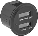 |
Display running time on a machine so you can schedule preventative maintenance. These counters have two displays. One display shows the total running time and cannot be reset; the other shows the time elapsed since the last maintenance and can be wired for remote reset.
Output Relay Current @ Input Voltage—The output relay turns on an indicator light and sends a signal to another device when the counter reaches a set point. The signal can start/stop a process or trigger an alarm.
Overall | |||||||||||||||||||||||||||||||||||||||||||||||||||||||||||||||||||||||||||||||||||||||||||||||||||
|---|---|---|---|---|---|---|---|---|---|---|---|---|---|---|---|---|---|---|---|---|---|---|---|---|---|---|---|---|---|---|---|---|---|---|---|---|---|---|---|---|---|---|---|---|---|---|---|---|---|---|---|---|---|---|---|---|---|---|---|---|---|---|---|---|---|---|---|---|---|---|---|---|---|---|---|---|---|---|---|---|---|---|---|---|---|---|---|---|---|---|---|---|---|---|---|---|---|---|---|
Resettable | Counting Direction | No. of Digits | No. of Set Points | For Panel Cutout Dia. | Dp. | Dia. | Operating Voltage | Output Relay Current @ Input Voltage | Features | Enclosure Rating | Each | ||||||||||||||||||||||||||||||||||||||||||||||||||||||||||||||||||||||||||||||||||||||||
Press On | |||||||||||||||||||||||||||||||||||||||||||||||||||||||||||||||||||||||||||||||||||||||||||||||||||
Wire Lead Connection | |||||||||||||||||||||||||||||||||||||||||||||||||||||||||||||||||||||||||||||||||||||||||||||||||||
| No | Up | 6 | 1 | 2" | 1.7" | 2.3" | 85V AC to 265V AC, 90V DC to 360V DC | 0.2 amp @ 265V AC, 0.2 amp @ 40V DC | Set Point Indicator Light | IP67 | 17045T72 | 0000000 | |||||||||||||||||||||||||||||||||||||||||||||||||||||||||||||||||||||||||||||||||||||||
| No | Up | 6 | 1 | 2" | 1.7" | 2.3" | 10V DC to 40V DC | 0.2 amp @ 265V AC, 0.2 amp @ 40V DC | Set Point Indicator Light | IP67 | 17045T71 | 000000 | |||||||||||||||||||||||||||||||||||||||||||||||||||||||||||||||||||||||||||||||||||||||
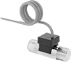
Ultra-Low-Flow Flow Transmitters
 |
Often used in low-flow metering applications for lubricants or antifreeze, these transmitters measure flow rate and send the data to a remote display or programmable logic controller (PLC). To measure flow, they have oval-shaped gears that move the liquid through the flowmeter—how fast the gears turn correspond to the flow rate. Also known as transducers, they help you monitor status or control equipment by converting measurements to an electrical pulse that can be interpreted by receiving devices. The higher the flow, the more pulses they send. Mount them inline with your pipe system. They’re accurate in any mounting orientation.
These transmitters are calibrated with oil but can be used with other liquids and will generally measure accurately, even if they differ in viscosity and density.
Flow Measurement Type | Pipe Connections | Flow Range, ml/min | Accuracy | Overall Ht. | Dia. | Max. Pressure @ Temp. | Temp. Range, ° F | Seal Material | Input Voltage Range, V DC | Mounting Position | Field Recalibratable | Pulse Frequency per Volume, pulse per ml | Each | ||||||||||||||||||||||||||||||||||||||||||||||||||||||||||||||||||||||||||||||||||||||
|---|---|---|---|---|---|---|---|---|---|---|---|---|---|---|---|---|---|---|---|---|---|---|---|---|---|---|---|---|---|---|---|---|---|---|---|---|---|---|---|---|---|---|---|---|---|---|---|---|---|---|---|---|---|---|---|---|---|---|---|---|---|---|---|---|---|---|---|---|---|---|---|---|---|---|---|---|---|---|---|---|---|---|---|---|---|---|---|---|---|---|---|---|---|---|---|---|---|---|---|
One Digital Pulse Output—Wire Lead Connection | |||||||||||||||||||||||||||||||||||||||||||||||||||||||||||||||||||||||||||||||||||||||||||||||||||
316 Stainless Steel Body | |||||||||||||||||||||||||||||||||||||||||||||||||||||||||||||||||||||||||||||||||||||||||||||||||||
| Positive Displacement | 1/8 NPT Female | 3 to 300 | ±0.5% | 2 7/8" | 1 1/2" | 1,450 psi @ 70° F | -22 to 176 | Viton® Fluoroelastomer | 4 to 26 | Any Angle | No | 9 | 4126K73 | 000000000 | |||||||||||||||||||||||||||||||||||||||||||||||||||||||||||||||||||||||||||||||||||||
| Positive Displacement | 1/8 NPT Female | 10 to 1,000 | ±0.5% | 2 7/8" | 1 15/16" | 1,450 psi @ 70° F | -22 to 176 | Viton® Fluoroelastomer | 4 to 26 | Any Angle | No | 4 | 4126K74 | 00000000 | |||||||||||||||||||||||||||||||||||||||||||||||||||||||||||||||||||||||||||||||||||||
Large-Display Digital Timers
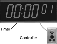 |
Read elapsed or remaining time from up to 150 ft. away—roughly half the length of a football field. These timers count up and down from zero. When counting down past zero, they flash and display a negative symbol before the time. To start, pause, and reset these timers, they require a controller (sold separately).
Controllers—The controller comes with a 20 ft. RJ45 cable to connect it to the timer.
Splitters—Add a splitter to connect two timers to the same controller.
Timers | Controllers | Splitters | ||||||||||||||||||
|---|---|---|---|---|---|---|---|---|---|---|---|---|---|---|---|---|---|---|---|---|
Case | ||||||||||||||||||||
Timing Functions | Max. No. of Events | Max. Timer Duration, hr. | Max. Alarm Duration | Timer Resolution, sec. | Ht. | Wd. | Dp. | Material | Color | Electrical Connection Type | Includes | Features | Each | Each | Each | |||||
| Count Up Count Down Pause | 1 | 100 | Continuous | 1 | 6 1/4" | 15 1/2" | 1 1/2" | Plastic | Black | Hardwire | Mounting Bracket | Alarm | 7384N12 | 0000000 | 7384N11 | 0000000 | 7384N13 | 000000 | ||
Flow Transmitters
 |
Turbine Flow Measurement |
Flow Measurement Type | Pipe Connections | Flow Range, gpm | End-to-End Lg. | Accuracy | Max. Pressure @ Temp. | Temp. Range, ° F | Input Voltage Range, V DC | Mounting Position | Field Recalibratable | Pulse Freq., Hz | Each | ||||||||||||||||||||||||||||||||||||||||||||||||||||||||||||||||||||||||||||||||||||||||
|---|---|---|---|---|---|---|---|---|---|---|---|---|---|---|---|---|---|---|---|---|---|---|---|---|---|---|---|---|---|---|---|---|---|---|---|---|---|---|---|---|---|---|---|---|---|---|---|---|---|---|---|---|---|---|---|---|---|---|---|---|---|---|---|---|---|---|---|---|---|---|---|---|---|---|---|---|---|---|---|---|---|---|---|---|---|---|---|---|---|---|---|---|---|---|---|---|---|---|---|
One Analog Transmitter/Digital Pulse Output—Wire Lead Connection | |||||||||||||||||||||||||||||||||||||||||||||||||||||||||||||||||||||||||||||||||||||||||||||||||||
Nylon Body with Nylon Fitting | |||||||||||||||||||||||||||||||||||||||||||||||||||||||||||||||||||||||||||||||||||||||||||||||||||
| Turbine | 1/4 NPT Male | 0.026 to 0.65 | 1 3/4" | ±3% | 362 psi @ 212° F | -4 to 212 | 5 to 24 | Any Angle | No | 36 to 902 | 4386N201 | 0000000 | |||||||||||||||||||||||||||||||||||||||||||||||||||||||||||||||||||||||||||||||||||||||
| Turbine | 3/8 NPT Male | 0.13 to 1.3 | 2 5/32" | ±3% | 362 psi @ 212° F | -4 to 212 | 5 to 24 | Any Angle | No | 56 to 565 | 4386N202 | 000000 | |||||||||||||||||||||||||||||||||||||||||||||||||||||||||||||||||||||||||||||||||||||||
| Turbine | 3/8 NPT Male | 0.26 to 4 | 2 5/32" | ±3% | 362 psi @ 212° F | -4 to 212 | 5 to 24 | Any Angle | No | 36 to 553 | 4386N203 | 000000 | |||||||||||||||||||||||||||||||||||||||||||||||||||||||||||||||||||||||||||||||||||||||
| Turbine | 3/8 NPT Male | 0.53 to 9.2 | 2 5/32" | ±3% | 362 psi @ 212° F | -4 to 212 | 5 to 24 | Any Angle | No | 25 to 435 | 4386N204 | 000000 | |||||||||||||||||||||||||||||||||||||||||||||||||||||||||||||||||||||||||||||||||||||||
| Turbine | 3/4 NPT Male | 1.32 to 17.17 | 2 15/16" | ±3% | 362 psi @ 212° F | -4 to 212 | 5 to 24 | Any Angle | No | 17 to 227 | 4386N205 | 000000 | |||||||||||||||||||||||||||||||||||||||||||||||||||||||||||||||||||||||||||||||||||||||
Brass Body with Brass Fitting | |||||||||||||||||||||||||||||||||||||||||||||||||||||||||||||||||||||||||||||||||||||||||||||||||||
| Turbine | 3/8 NPT Male | 0.5 to 2.11 | 2 5/32" | ±3% | 362 psi @ 212° F | -4 to 212 | 5 to 24 | Any Angle | No | 132 to 559 | 4386N206 | 000000 | |||||||||||||||||||||||||||||||||||||||||||||||||||||||||||||||||||||||||||||||||||||||
| Turbine | 3/8 NPT Male | 0.8 to 6.6 | 2 5/32" | ±3% | 362 psi @ 212° F | -4 to 212 | 5 to 24 | Any Angle | No | 46 to 383 | 4386N207 | 000000 | |||||||||||||||||||||||||||||||||||||||||||||||||||||||||||||||||||||||||||||||||||||||
Socket-Connect Flowmeter/Totalizers with Remote Display
Sensors
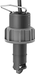 |
Sensors thread onto the tee fitting.
