


Filter by
Angle Measured
Distance Measured
Probe Type
Manufacturer Model Number
Container Type
U.S.–Mexico–Canada Agreement (USMCA) Qualifying
Export Control Classification Number (ECCN)
Material
REACH
RoHS
Contact Point Material
DFARS Specialty Metals
Dial Indicator Size
Finish
Performance
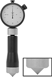
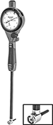
Starrett Countersink Gauges
 |
With Cone Probe |
Mate your fastener and countersink perfectly for a secure hold with these Starrett gauges. They are often used in vehicle and metal manufacturing to check the top diameter and countersink angle of a hole. When the conical probe touches the hole’s angled walls, the diameter will display on the dial. You can verify the countersink angle based on how snug the probe fits into the hole. Even when you lift the gauge out of the hole, your measurement will stay on the dial until you press the reset button.
Choose a gauge with an angle that’s equal to the angle of the countersunk hole you’re trying to measure.
Dial | |||||||||||||||||||||||||||||||||||||||||||||||||||||||||||||||||||||||||||||||||||||||||||||||||||
|---|---|---|---|---|---|---|---|---|---|---|---|---|---|---|---|---|---|---|---|---|---|---|---|---|---|---|---|---|---|---|---|---|---|---|---|---|---|---|---|---|---|---|---|---|---|---|---|---|---|---|---|---|---|---|---|---|---|---|---|---|---|---|---|---|---|---|---|---|---|---|---|---|---|---|---|---|---|---|---|---|---|---|---|---|---|---|---|---|---|---|---|---|---|---|---|---|---|---|---|
Distance Measured | Accuracy | Measuring Increments | Probe Type | Material | Dial Indicator Size | Dia. | Face Color | Contact Point Material | Mfr. Model No. | Each | |||||||||||||||||||||||||||||||||||||||||||||||||||||||||||||||||||||||||||||||||||||||||
82° Angle Measured | |||||||||||||||||||||||||||||||||||||||||||||||||||||||||||||||||||||||||||||||||||||||||||||||||||
| 0.02" to 0.17" | ±0.0002" | 0.002" | Cone | Steel | AGD Group 1 | 1 5/8" | White | Steel | 687-1Z | 21125A363 | 0000000 | ||||||||||||||||||||||||||||||||||||||||||||||||||||||||||||||||||||||||||||||||||||||||
| 0.16" to 0.36" | ±0.0002" | 0.002" | Cone | Steel | AGD Group 1 | 1 5/8" | White | Steel | 687-2Z | 21125A364 | 000000 | ||||||||||||||||||||||||||||||||||||||||||||||||||||||||||||||||||||||||||||||||||||||||
90° Angle Measured | |||||||||||||||||||||||||||||||||||||||||||||||||||||||||||||||||||||||||||||||||||||||||||||||||||
| 0.02" to 0.17" | ±0.0002" | 0.002" | Cone | Steel | AGD Group 1 | 1 5/8" | White | Steel | 688-1Z | 21125A372 | 000000 | ||||||||||||||||||||||||||||||||||||||||||||||||||||||||||||||||||||||||||||||||||||||||
| 0.16" to 0.36" | ±0.0002" | 0.002" | Cone | Steel | AGD Group 1 | 1 5/8" | White | Steel | 688-2Z | 21125A373 | 000000 | ||||||||||||||||||||||||||||||||||||||||||||||||||||||||||||||||||||||||||||||||||||||||
| 0.36" to 0.56" | ±0.0002" | 0.002" | Cone | Steel | AGD Group 1 | 1 5/8" | White | Steel | 688-3Z | 21125A374 | 000000 | ||||||||||||||||||||||||||||||||||||||||||||||||||||||||||||||||||||||||||||||||||||||||
100° Angle Measured | |||||||||||||||||||||||||||||||||||||||||||||||||||||||||||||||||||||||||||||||||||||||||||||||||||
| 0.02" to 0.17" | ±0.0002" | 0.002" | Cone | Steel | AGD Group 1 | 1 5/8" | White | Steel | 689-1Z | 21125A381 | 000000 | ||||||||||||||||||||||||||||||||||||||||||||||||||||||||||||||||||||||||||||||||||||||||
| 0.16" to 0.36" | ±0.0002" | 0.002" | Cone | Steel | AGD Group 1 | 1 5/8" | White | Steel | 689-2Z | 21125A382 | 000000 | ||||||||||||||||||||||||||||||||||||||||||||||||||||||||||||||||||||||||||||||||||||||||
| 0.36" to 0.56" | ±0.0002" | 0.002" | Cone | Steel | AGD Group 1 | 1 5/8" | White | Steel | 689-3Z | 21125A383 | 000000 | ||||||||||||||||||||||||||||||||||||||||||||||||||||||||||||||||||||||||||||||||||||||||
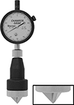
Starrett Chamfer Gauges
 |
With Three-Blade Probe |
Make sure the top diameter of a chamfered hole isn’t too big or too small. These gauges are often used as a quality control check after milling, drilling, and reaming. Press the three-blade probe into a chamfered hole and twist slightly to center. Once the blades touch the hole’s slopes, the dial will display the diameter. Zero set these gauges on a flat, ground surface when needed.
Choose a gauge with a measuring angle that’s greater than or equal to the angle of the chamfered hole you’re measuring.
Dial | |||||||||||||||||||||||||||||||||||||||||||||||||||||||||||||||||||||||||||||||||||||||||||||||||||
|---|---|---|---|---|---|---|---|---|---|---|---|---|---|---|---|---|---|---|---|---|---|---|---|---|---|---|---|---|---|---|---|---|---|---|---|---|---|---|---|---|---|---|---|---|---|---|---|---|---|---|---|---|---|---|---|---|---|---|---|---|---|---|---|---|---|---|---|---|---|---|---|---|---|---|---|---|---|---|---|---|---|---|---|---|---|---|---|---|---|---|---|---|---|---|---|---|---|---|---|
Distance Measured Range | Accuracy | Measuring Increments | Probe Type | Material | Dia. | Face Color | Contact Point Material | Mfr. Model No. | Each | ||||||||||||||||||||||||||||||||||||||||||||||||||||||||||||||||||||||||||||||||||||||||||
0° to 90° Angle Measured | |||||||||||||||||||||||||||||||||||||||||||||||||||||||||||||||||||||||||||||||||||||||||||||||||||
| 0" to 0.38" | ±0.002" | 0.001" | Three Blade | Black-Oxide Steel | 2 1/4" | White | Steel | 683-1Z | 21125A332 | 0000000 | |||||||||||||||||||||||||||||||||||||||||||||||||||||||||||||||||||||||||||||||||||||||||
| 0" to 0.5" | ±0.002" | 0.001" | Three Blade | Black-Oxide Steel | 2 1/4" | White | Steel | 683-2Z | 21125A333 | 000000 | |||||||||||||||||||||||||||||||||||||||||||||||||||||||||||||||||||||||||||||||||||||||||
| 0" to 1" | ±0.002" | 0.001" | Three Blade | Black-Oxide Steel | 2 1/4" | White | Steel | 683-3Z | 21125A334 | 000000 | |||||||||||||||||||||||||||||||||||||||||||||||||||||||||||||||||||||||||||||||||||||||||
| 1" to 2" | ±0.002" | 0.001" | Three Blade | Black-Oxide Steel | 2 1/4" | White | Steel | 683-4Z | 21125A335 | 000000 | |||||||||||||||||||||||||||||||||||||||||||||||||||||||||||||||||||||||||||||||||||||||||
90° to 127° Angle Measured | |||||||||||||||||||||||||||||||||||||||||||||||||||||||||||||||||||||||||||||||||||||||||||||||||||
| 0" to 0.38" | ±0.002" | 0.001" | Three Blade | Black-Oxide Steel | 2 1/4" | White | Steel | 684-1Z | 21125A341 | 000000 | |||||||||||||||||||||||||||||||||||||||||||||||||||||||||||||||||||||||||||||||||||||||||
| 0" to 0.5" | ±0.002" | 0.001" | Three Blade | Black-Oxide Steel | 2 1/4" | White | Steel | 684-2Z | 21125A342 | 000000 | |||||||||||||||||||||||||||||||||||||||||||||||||||||||||||||||||||||||||||||||||||||||||
| 0" to 1" | ±0.002" | 0.001" | Three Blade | Black-Oxide Steel | 2 1/4" | White | Steel | 684-3Z | 21125A343 | 000000 | |||||||||||||||||||||||||||||||||||||||||||||||||||||||||||||||||||||||||||||||||||||||||
| 1" to 2" | ±0.002" | 0.001" | Three Blade | Black-Oxide Steel | 2 1/4" | White | Steel | 684-4Z | 21125A344 | 000000 | |||||||||||||||||||||||||||||||||||||||||||||||||||||||||||||||||||||||||||||||||||||||||
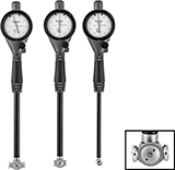
Starrett Dial Bore Gauge Sets
 |
With Interchangeable Anvil Probe |
Test for size deviations across a range of hole diameters. These sets include 3 gauges and over 25 anvils marked by size for quick changes. Use them to test engine cylinders, machine components, and other parts for issues with roundness and taper. They have a two-point contact system, which is the most common design for bore gauges. For a long service life, the jeweled bearings in each dial head resist wear, and a plastic cover protects the head from scratches and drops.
Check size deviations by first setting the desired measurement with a ring gauge, bore gauge calibrator, micrometer, or caliper. The dial will display the magnitude of variation from the set measurement.
Dial | |||||||||||||||
|---|---|---|---|---|---|---|---|---|---|---|---|---|---|---|---|
Distance Measured Range | Accuracy | Measuring Increments | Max. Dp. Measured | Performance | Measurement per Dial Rev. | Material | Dial Indicator Size | Dia. | Face Color | No. of Anvils | Features | Mfr. Model No. | Each | ||
| 0.7" to 6" | ±0.0005" | 0.0005" | 6" | Changeable Anvil | 0.05" | Steel | AGD Group 2 | 2 1/4" | White | 27 | Laser-Marked Anvils | S3089Z-131-6J | 7504N11 | 000000000 | |
| 50 mm to 160 mm | ±0.01 mm | 0.01 mm | 150 mm | Changeable Anvil | 0.1 mm | Steel | AGD Group 2 | 2 1/4" | Yellow | 26 | Laser-Marked Anvils | S3089MZ-181-160J | 7504N12 | 00000000 | |
Starrett Small-Bore Dial Gauges
 |
With Full-Ball Probe |
The dial on these gauges displays size deviations in real time. These gauges measure small slots and bores in precision parts, such as electronics, where even small size deviations can cause inefficiencies. Thanks to its full-ball design, the end of these gauges makes 360° contact inside the bore, so it's easier to center in tight spaces than anvil or spring-loaded contacts. This symmetrical ball is also less likely to tilt within the bore than half-ball gauges, which helps to avoid skewed measurements from improper placement.
Insert the probe into a bore and turn the knob on the handle to expand the contacts. To check size deviations, set the desired measurement with a ring gauge, bore gauge calibrator, micrometer, or caliper. The dial will display the magnitude of variation from the set measurement. To find the bore diameter, use a micrometer to measure the distance across the contacts.
Dial | ||||||||||||||
|---|---|---|---|---|---|---|---|---|---|---|---|---|---|---|
Distance Measured Range | Accuracy | Measuring Increments | Max. Dp. Measured | Probe Type | Measurement per Dial Rev. | Material | Dial Indicator Size | Dia. | Face Color | No. of Anvils | Mfr. Model No. | Each | ||
| 0.56" to 1.565" | ±0.0001" | 0.0001" | 5" | Full-Ball | 0.01" | Steel | AGD Group 1 | 1 5/8" | White | 8 | 82CZ | 21125A9 | 000000000 | |
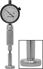
Starrett Dial Bore Gauges
 |
With Interchangeable Anvil Probe |
Check a hole’s diameter and detect out-of-roundness problems. Often used to test engine cylinders and machine components, these gauges catch issues with roundness and taper. They have the most common design for bore gauges, which is a two-point contact system. The dial head’s highly sensitive jeweled bearings resist wear for a long service life.
To use these bore gauges, set a baseline measurement with a ring gauge, calibrator, micrometer, or caliper. The variation from the set measurement displays on the dial right away, so there’s no need for conversions. Swap out the anvil to measure bores of different diameters. Marked by size, the anvils are quick to spot and select.
Dial | ||||||||||||||||
|---|---|---|---|---|---|---|---|---|---|---|---|---|---|---|---|---|
Distance Measured Range | Accuracy | Measuring Increments | Max. Dp. Measured | Performance | Measurement per Dial Rev. | Material | Dial Indicator Size | Dia. | Face Color | No. of Anvils | Features | Includes | Mfr. Model No. | Each | ||
| 0.7" to 1.5" | ±0.0005" | 0.0005" | 6" | Changeable Anvil | 0.05" | Steel | AGD Group 2 | 2 1/4" | White | 10 | Laser-Marked Anvils | — | 3089Z-131-715J | 6701N101 | 0000000 | |
| 1.4" to 2.4" | ±0.0005" | 0.0005" | 6" | Changeable Anvil | 0.05" | Steel | AGD Group 2 | 2 1/4" | White | 6 | Laser-Marked Anvils | — | 3089Z-131-1424J | 6701N102 | 000000 | |
| 2" to 6" | ±0.0005" | 0.0005" | 6" | Changeable Anvil | 0.05" | Steel | AGD Group 2 | 2 1/4" | White | 11 | Laser-Marked Anvils | 2" Lg. Extension | 3089Z-131-26J | 6701N103 | 000000 | |
