


About Shaft Couplings
More
Set Screw Flexible Shaft Couplings
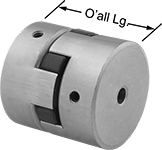
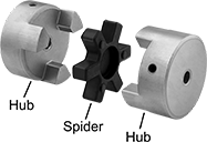
Each hub includes a set screw (unless noted), which bites into your shaft to hold the coupling in place. Also known as Lovejoy® couplings, these three-piece couplings have a spider-shaped cushion between two hubs to reduce shock and handle minor shaft misalignment.
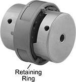
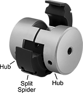
A complete coupling consists of two hubs and one spider, or two hubs, one split spider, and one retaining ring (all components sold separately). Split spiders are easier to install and replace than standard spiders because there’s no need for tools or removing your hubs. Twist-lock them in place using a retaining ring.
Buna-N spiders provide good vibration damping and chemical resistance. Hytrel spiders provide fair vibration damping and excellent chemical resistance. Polyurethane spiders and split spiders provide fair vibration damping and good chemical resistance.
![]() For technical drawings and 3-D models, click on a part number.
For technical drawings and 3-D models, click on a part number.
Buna-N Rubber Spiders | |||||||||||||
|---|---|---|---|---|---|---|---|---|---|---|---|---|---|
Iron Hubs | Misalignment Capability | ||||||||||||
| Overall Lg. | OD | For Shaft Type | For Motion Type | For Shaft Dia. | Each | Max. Speed, rpm | Max. Torque, in.-lbs. | Parallel | Angular | Temp. Range, °F | Each | ||
| 2 27/32" | 2 35/64" | Keyed | Forward/Reverse, Start/Stop | 1 3/16" | 0000000 | 000000 | 7,000 | 315 | 0.015" | 1° | -40° to 212° | 0000000 | 000000 |
| 3 31/64" | 2 35/64" | Keyed | Forward/Reverse, Start/Stop | 1 3/16" | 0000000 | 00000 | 7,000 | 315 | 0.015" | 1° | -40° to 212° | 0000000 | 00000 |
| 4 7/32" | 3 21/64" | Keyed | Forward/Reverse, Start/Stop | 1 3/16" | 0000000 | 00000 | 5,000 | 790 | 0.015" | 1° | -40° to 212° | 0000000 | 00000 |
| 4 1/2" | 3 3/4" | Keyed | Forward/Reverse, Start/Stop | 1 3/16" | 0000000 | 000000 | 5,000 | 1,240 | 0.015" | 1° | -40° to 212° | 0000000 | 00000 |
Hytrel Rubber Spiders | |||||||||||||
|---|---|---|---|---|---|---|---|---|---|---|---|---|---|
Iron Hubs | Misalignment Capability | ||||||||||||
| Overall Lg. | OD | For Shaft Type | For Motion Type | For Shaft Dia. | Each | Max. Speed, rpm | Max. Torque, in.-lbs. | Parallel | Angular | Temp. Range, °F | Each | ||
| 2 27/32" | 2 35/64" | Keyed | Forward/Reverse, Start/Stop | 1 3/16" | 0000000 | 000000 | 3,600 | 790 | 0.015" | 0.5° | -55° to 245° | 0000000 | 0000000 |
| 3 31/64" | 2 35/64" | Keyed | Forward/Reverse, Start/Stop | 1 3/16" | 0000000 | 00000 | 3,600 | 790 | 0.015" | 0.5° | -55° to 245° | 0000000 | 000000 |
| 4 7/32" | 3 21/64" | Keyed | Forward/Reverse, Start/Stop | 1 3/16" | 0000000 | 00000 | 3,600 | 2,265 | 0.015" | 0.5° | -55° to 245° | 0000000 | 000000 |
| 4 1/2" | 3 3/4" | Keyed | Forward/Reverse, Start/Stop | 1 3/16" | 0000000 | 000000 | 3,600 | 3,705 | 0.015" | 0.5° | -55° to 245° | 0000000 | 000000 |
Polyurethane Spiders | |||||||||||||
|---|---|---|---|---|---|---|---|---|---|---|---|---|---|
Iron Hubs | Misalignment Capability | ||||||||||||
| Overall Lg. | OD | For Shaft Type | For Motion Type | For Shaft Dia. | Each | Max. Speed, rpm | Max. Torque, in.-lbs. | Parallel | Angular | Temp. Range, °F | Each | ||
| 2 27/32" | 2 35/64" | Keyed | Forward/Reverse, Start/Stop | 1 3/16" | 0000000 | 000000 | 3,600 | 475 | 0.015" | 1° | -30° to 160° | 0000000 | 000000 |
| 3 31/64" | 2 35/64" | Keyed | Forward/Reverse, Start/Stop | 1 3/16" | 0000000 | 00000 | 3,600 | 475 | 0.015" | 1° | -30° to 160° | 0000000 | 00000 |
| 4 7/32" | 3 21/64" | Keyed | Forward/Reverse, Start/Stop | 1 3/16" | 0000000 | 00000 | 3,600 | 1,185 | 0.015" | 1° | -30° to 160° | 0000000 | 000000 |
| 4 1/2" | 3 3/4" | Keyed | Forward/Reverse, Start/Stop | 1 3/16" | 0000000 | 000000 | 3,600 | 1,860 | 0.015" | 1° | -30° to 160° | 0000000 | 000000 |
Polyurethane Split Spiders | |||||||||||||||
|---|---|---|---|---|---|---|---|---|---|---|---|---|---|---|---|
Iron Hubs | Misalignment Capability | 347 Stainless Steel Retaining Rings | |||||||||||||
| Overall Lg. | OD | For Shaft Type | For Motion Type | For Shaft Dia. | Each | Max. Speed, rpm | Max. Torque, in.-lbs. | Parallel | Angular | Temp. Range, °F | Each | Each | |||
| 2 27/32" | 2 35/64" | Keyed | Forward/Reverse, Start/Stop | 1 3/16" | 0000000 | 000000 | 7,700 | 1,110 | 0.03" | 2° | -30° to 200° | 0000000 | 000000 | 0000000 | 000000 |
| 3 31/64" | 2 35/64" | Keyed | Forward/Reverse, Start/Stop | 1 3/16" | 0000000 | 00000 | 7,700 | 1,110 | 0.03" | 2° | -30° to 200° | 0000000 | 00000 | 0000000 | 00000 |
| 4 7/32" | 3 21/64" | Keyed | Forward/Reverse, Start/Stop | 1 3/16" | 0000000 | 00000 | 5,900 | 2,180 | 0.03" | 2° | -30° to 200° | 0000000 | 000000 | 0000000 | 000000 |
Clamping Shaft Couplings
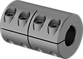

Designed to grip evenly around your shaft, clamping couplings provide more holding power than set screw couplings without marring the shaft. Slide onto the end of your shaft and tighten the clamping screws to secure. Good for high-torque applications, rigid couplings connect two shafts that are aligned, allowing for no relative movement between the shafts.
Stainless steel couplings have excellent corrosion resistance.
![]() For technical drawings and 3-D models, click on a part number.
For technical drawings and 3-D models, click on a part number.
| For Shaft Dia. | Overall Lg. | OD | Max. Speed, rpm | Max. Torque, in.-lbs. | For Motion Type | Each | |
Steel | |||||||
|---|---|---|---|---|---|---|---|
For Keyed Shafts | |||||||
| 1 3/16" × 1 3/16" | 3 1/4" | 2 1/16" | 4,000 | 5,000 | Forward/Reverse, Start/Stop, Continuous | 00000000 | 0000000 |
For Round Shafts | |||||||
| 1 3/16" × 1" | 3 1/4" | 2 1/16" | 4,000 | 5,000 | Forward/Reverse, Start/Stop, Continuous | 00000000 | 000000 |
| 1 3/16" × 1 3/16" | 3 1/4" | 2 1/16" | 4,000 | 5,000 | Forward/Reverse, Start/Stop, Continuous | 00000000 | 00000 |
303 Stainless Steel | |||||||
For Keyed Shafts | |||||||
| 1 3/16" × 1 3/16" | 3 1/4" | 2 1/16" | 4,000 | 3,200 | Forward/Reverse, Start/Stop, Continuous | 0000000 | 000000 |
Two-Piece Shaft Coupling Bridges
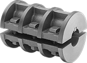
When your shafts are not close enough to use standard couplings, these have the length to bridge the gap. Install them anywhere on a shaft without removing components or having access to the ends of the shaft. Tighten the clamping screws to secure. Good for high-torque applications, rigid couplings connect two shafts that are aligned, allowing for no relative movement between the shafts.
![]() For technical drawings and 3-D models, click on a part number.
For technical drawings and 3-D models, click on a part number.
| For Shaft Dia. | Overall Lg. | OD | Max. Speed, rpm | Max. Torque, in.-lbs. | For Motion Type | Each | |
Cast Iron | |||||||
|---|---|---|---|---|---|---|---|
For Keyed Shafts | |||||||
| 1 3/16" | 6 1/4" | 4 1/4" | 5,360 | 2,000 | Forward/Reverse, Start/Stop, Continuous | 0000000 | 0000000 |
Single U-Joints
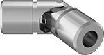

Connect and transfer torque between two shafts that are misaligned at an angle. Your shafts’ misalignment will affect the speed and torque these U-joints will be able to transmit. The more the shafts are misaligned, the less speed and torque they’ll be able to transmit.
Pin-and-block U-joints handle higher torque at lower speeds than other joint types such as those with needle bearings, making them a good choice for most applications. To extend their life by keeping lubricant in and contaminants out, use the grooves on their body to add a cover (sometimes called bellows or boots).
Steel U-joints are strong and handle more torque than zinc U-joints.
U-joints for keyed shafts connect to shafts with set screws. Unlike U-joints that use spring pins, there’s no drilling required.
![]() For technical drawings and 3-D models, click on a part number.
For technical drawings and 3-D models, click on a part number.
For Shaft | Torque | ||||||||||
|---|---|---|---|---|---|---|---|---|---|---|---|
| Dia. | Dp. | Joint Dia. | Overall Lg. | Max. Operating Angle | Max. Speed, rpm | Max. Torque, in.-lbs. | 3° Operating Angle | 10° Operating Angle | Shaft Mount Type | Each | |
Pin-and-Block Joint | |||||||||||
Steel—For Keyed Shafts | |||||||||||
| 1 3/16" | 1 1/2" | 2" | 5 7/16" | 25° | 1,750 | 15,600 | 2,635 in.-lbs. @ 300 rpm | 885 in.-lbs. @ 300 rpm | Set Screw | 0000000 | 0000000 |
Torque Limiters for Chain and Belt Drives
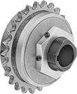
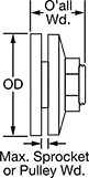
Prevent damage from overloading. When overloaded, these limiters cause your sprocket or pulley to slip. Once the overload is removed, the limiters automatically reset. Set the torque within the range listed. Friction discs are between the hub and pressure plate.
Double-spring limiters have a second spring for handling nearly twice the torque of single-spring limiters.
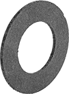
Optional sprockets are designed specifically to fit their corresponding limiters. These hubless sprockets are not interchangeable.
![]() For technical drawings and 3-D models, click on a part number.
For technical drawings and 3-D models, click on a part number.
Torque Limiters | |||||||||||||||||||
|---|---|---|---|---|---|---|---|---|---|---|---|---|---|---|---|---|---|---|---|
Keyway | Torque | Optional Sprockets | Replacement Friction Discs for Torque Limiters | Replacement Bushings for Optional Sprockets | |||||||||||||||
| For Shaft Dia. | OD | O'all Wd. | Wd. | Dp. | For Max. Sprocket or Pulley Wd. | Friction Disc Thick. | Min., ft.-lbs. | Max., ft.-lbs. | Hub Material | Each | For Roller Chain Trade Size | Each | Each | For Roller Chain Trade Size | Each | ||||
Single Spring | |||||||||||||||||||
| 1 3/16" | 5" | 2 7/8" | 1/4" | 1/8" | 5/8" | 1/8" | 90 | 250 | Steel | 00000000 | 0000000 | 0000000 | 000000 | 0000000 | 000000 | 000000 | 00000 | ||
Double Spring | |||||||||||||||||||
| 1 3/16" | 5" | 2 7/8" | 1/4" | 1/8" | 5/8" | 1/8" | 120 | 400 | Steel | 00000000 | 000000 | 0000000 | 00000 | 0000000 | 00000 | 000000 | 0000 | ||
| For OD | Each | |
| 5" | 00000000 | 000000 |