


About Shaft Couplings
More
Set Screw Flexible Shaft Couplings
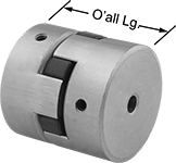
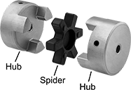
Each hub includes a set screw (unless noted), which bites into your shaft to hold the coupling in place. Also known as Lovejoy® couplings, these three-piece couplings have a spider-shaped cushion between two hubs to reduce shock and handle minor shaft misalignment.
Buna-N spiders provide good vibration damping and chemical resistance. Hytrel spiders provide fair vibration damping and excellent chemical resistance.
![]() For technical drawings and 3-D models, click on a part number.
For technical drawings and 3-D models, click on a part number.
High-Torque Set Screw Flexible Shaft Couplings
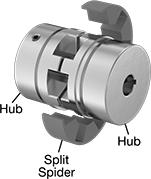
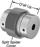
The thick split spider on these couplings takes on twice as much torque as standard split spiders, while a set screw holds the hubs in place on your shaft. Also known as jaw couplings, use them to connect motors to pumps, mixers, and other high-torque equipment. You don’t need to lubricate them.
For a complete coupling, you’ll need two hubs, one split spider, and a split spider cover (all sold separately).
Hubs attach to the end of your shaft.
Split spiders cushion between the two hubs to dampen vibration, reduce shocks, and handle shaft misalignment, extending the life of bearings, seals, and motors. You can replace them without having to remove the hubs or move your shaft and equipment around, which reduces the risk of needing to realign the shaft. Spiders with medium-soft hardness are the most commonly used and are good for applications that start, stop, and reverse often. Those with medium hardness handle higher torque than those with medium-soft hardness, but they don’t reduce vibration as well.
Split spider covers hold the spider in place.
![]() For technical drawings and 3-D models, click on a part number.
For technical drawings and 3-D models, click on a part number.
Urethane Split Spiders | |||||||||||||||
|---|---|---|---|---|---|---|---|---|---|---|---|---|---|---|---|
Steel Hubs | Misalignment Capability | Steel Split Spider Covers | |||||||||||||
| Overall Lg. | OD | For Motion Type | For Shaft Dia. | Each | Max. Speed, rpm | Max. Torque, in.-lbs. | Parallel | Angular | Temp. Range, °F | Color | Each | Each | |||
| 6 1/16" | 3 33/64" | Forward/Reverse, Start/Stop | 2 1/4" | 000000 | 0000000 | 6,000 | 7,065 | 0.038" | 2° | -60° to 212° | Red | 0000000 | 000000 | 0000000 | 0000000 |
Urethane Split Spiders | |||||||||||||||
|---|---|---|---|---|---|---|---|---|---|---|---|---|---|---|---|
Steel Hubs | Misalignment Capability | Steel Split Spider Covers | |||||||||||||
| Overall Lg. | OD | For Motion Type | For Shaft Dia. | Each | Max. Speed, rpm | Max. Torque, in.-lbs. | Parallel | Angular | Temp. Range, °F | Color | Each | Each | |||
| 6 1/16" | 3 33/64" | Forward/Reverse, Start/Stop | 2 1/4" | 000000 | 0000000 | 6,000 | 14,000 | 0.038" | 2° | -60° to 212° | Blue | 0000000 | 000000 | 0000000 | 0000000 |
Urethane Split Spiders | |||||||||||||||
|---|---|---|---|---|---|---|---|---|---|---|---|---|---|---|---|
Steel Hubs | Misalignment Capability | Steel Split Spider Covers | |||||||||||||
| Overall Lg. | OD | For Motion Type | For Shaft Dia. | Each | Max. Speed, rpm | Max. Torque, in.-lbs. | Parallel | Angular | Temp. Range, °F | Color | Each | Each | |||
| 6 1/16" | 3 33/64" | Forward/Reverse, Start/Stop | 2 1/4" | 000000 | 0000000 | 6,000 | 14,000 | 0.038" | 2° | -60° to 350° | White | 0000000 | 0000000 | 0000000 | 0000000 |
Shock-Absorbing Flexible Shaft Couplings
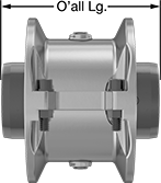
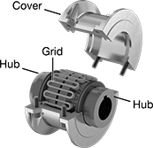
A strip of flexible spring steel wraps around the teeth of both hubs to absorb sharp, momentary load increases that can come from motor startups, emergency braking, or sudden impact with hard objects. When the shock load hits, the strip of spring steel (known as a grid) flexes to spread out the load. After the load passes, the grid straightens back out. They're commonly found in wire drawing and cutting machines, pulverizers, and mixers. Compared to spider couplings, jaw couplings, and other flexible shaft couplings, these handle higher torque while taking up less space. All have keyed bores to work with keyed shafts, which transmit higher torque with less slippage than round shafts.
A complete coupling consists of two hubs as well as a grid and cover assembly (all sold separately). The grid and cover assembly includes a spring steel grid, aluminum cover, rubber seals, and grease for lubrication. When ordering, please choose components that have the same manufacturer series number, otherwise the grid will not fit.
![]() For technical drawings and 3-D models, click on a part number.
For technical drawings and 3-D models, click on a part number.
Grid and Cover Assemblies | ||||||||||||||||
|---|---|---|---|---|---|---|---|---|---|---|---|---|---|---|---|---|
Hubs | Misalignment Capability | Replacement Grids | Replacement Seal Kits | |||||||||||||
| O'all Lg. | OD | For Motion Type | Mfr. Series | For Shaft Dia. | Each | Parallel | Angular | Max. Speed, rpm | Max. Torque, in.-lbs. | Each | Each | Each | ||||
Black-Oxide Steel | ||||||||||||||||
For Keyed Shaft | ||||||||||||||||
| 7 7/8" | 6 11/32" | Continuous, Forward/Reverse, Start/Stop | Martin (1090T) | 2 1/4" | 000000 | 0000000 | 0.016" | 0.25° | 3,600 | 33,000 | 00000000 | 0000000 | 00000000 | 0000000 | 00000000 | 000000 |
| Additional Grease (14 fl. oz. Grease Gun Cartridge) | 0000000 | Each | 000000 |
High-Speed Vibration-Damping Flexible Shaft Couplings
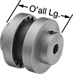
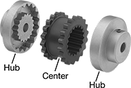
Use these gear-shaped couplings for high-speed and high-torque applications. A rubber center allows flexing so couplings can take on multiple types of misalignment while damping vibration and shock. With no metal-to-metal contact, there’s no need for lubrication. Fasten to your shafts by tightening the set screws, which bite into the shaft to hold it.
A complete coupling consists of two hubs and one center (each component sold separately).
Hubs have a keyway, except hubs for 1/4" and 3/8" shaft dia. do not have a keyway.
![]() For technical drawings and 3-D models, click on a part number.
For technical drawings and 3-D models, click on a part number.
Centers | |||||||||||||||
|---|---|---|---|---|---|---|---|---|---|---|---|---|---|---|---|
Hubs | Misalignment Capability | ||||||||||||||
| O'all Lg. | OD | For Motion Type | Material | For Shaft Dia. | Each | Max. Speed, rpm | Max. Torque, in.-lbs. | Parallel | Angular | Axial | Temp. Range, °F | Material | Each | ||
| 4 7/16" | 5 29/64" | Continuous | Cast Iron | 2 1/4" | 0000000 | 000000 | 4,500 | 1,135 | 0.02" | 1° | 0.125" | -30° to 275° | TPE Rubber | 0000000 | 000000 |
| 5 11/16" | 7 1/2" | Continuous | Cast Iron | 2 1/4" | 000000 | 000000 | 3,600 | 2,875 | 0.025" | 1° | 0.125" | -30° to 275° | TPE Rubber | 0000000 | 00000 |
High-Torque Flexible Shaft Couplings
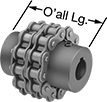
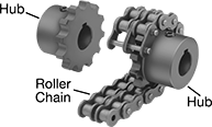
With a rugged roller-chain design, these couplings provide excellent torque and angular misalignment capacities. Lubrication is required. Fasten to your shaft by tightening the set screws, which bite into the shaft to hold it.
A complete coupling consists of two hubs and one roller chain (each component sold separately). Complete couplings meet ANSI B29.23M-1995.
Optional covers retain grease lubrication and provide protection from abrasion and corrosion.
![]() For technical drawings and 3-D models, click on a part number.
For technical drawings and 3-D models, click on a part number.
Steel Roller Chain | ||||||||||||||||
|---|---|---|---|---|---|---|---|---|---|---|---|---|---|---|---|---|
Steel Hubs | Misalignment Capability | Roller Chain | Orange Nylon Plastic Covers | |||||||||||||
| O'all Lg. | OD | OD with Cover | For Motion Type | For Shaft Dia. | Each | Max. Speed, rpm | Max. Torque, in.-lbs. | Parallel | Angular | No. | Standard | Each | Each | |||
| 3 29/64" | 5" | 6 3/8" | Continuous | 2 1/4" | 0000000 | 000000 | 3,000 | 10,900 | 0.012" | 1.5° | 60-2 | ANSI | 0000000 | 000000 | 0000000 | 0000000 |
Ultra-High-Torque Flexible Shaft Couplings
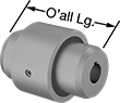
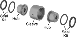
With a rigid gear design, these steel couplings transmit more torque than other couplings of the same size. Lubrication is required. To install, heat the hubs to expand them slightly and fit them onto the shaft. When they cool, hubs shrink to fit the shaft tightly.
A complete coupling consists of two hubs, one sleeve, and one seal kit (each component sold separately).
![]() For technical drawings and 3-D models, click on a part number.
For technical drawings and 3-D models, click on a part number.
Steel Sleeves | |||||||||||||||
|---|---|---|---|---|---|---|---|---|---|---|---|---|---|---|---|
Steel Hubs | Misalignment Capability | Seal Kits | |||||||||||||
| O'all Lg. | OD | For Motion Type | For Shaft Dia. | Each | Max. Speed, rpm | Max. Torque, in.-lbs. | Parallel | Angular | Axial | Each | Includes | Each | |||
| 4 3/4" | 5 1/2" | Continuous | 2 1/4" | 0000000 | 0000000 | 3,750 | 30,200 | 0.007" | 1° | 0.05" | 0000000 | 0000000 | Two Buna-N Rubber Lubrication Seals, Two Steel Snap Rings | 0000000 | 0000000 |
High-Grip Clamping Shaft Couplings
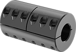
These couplings have the gripping strength to handle higher torque than most other couplings. Couplings clamp evenly around the shaft to create a mar-free hold. Slide onto the end of your shaft and tighten the clamping screws to secure. Good for high-torque applications, rigid couplings connect two shafts that are aligned, allowing for no relative movement between the shafts.
![]() For technical drawings and 3-D models, click on a part number.
For technical drawings and 3-D models, click on a part number.
| For Shaft Dia. | Overall Lg. | OD | Max. Speed, rpm | Max. Torque, in.-lbs. | For Motion Type | Each | |
Steel | |||||||
|---|---|---|---|---|---|---|---|
For Round Shafts | |||||||
| 2 1/4" | 6 1/2" | 3 3/4" | 3,500 | 12,320 | Forward/Reverse, Start/Stop, Continuous | 000000 | 0000000 |
Two-Piece Shaft Coupling Bridges
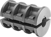
When your shafts are not close enough to use standard couplings, these have the length to bridge the gap. Install them anywhere on a shaft without removing components or having access to the ends of the shaft. Tighten the clamping screws to secure. Good for high-torque applications, rigid couplings connect two shafts that are aligned, allowing for no relative movement between the shafts.
![]() For technical drawings and 3-D models, click on a part number.
For technical drawings and 3-D models, click on a part number.
| For Shaft Dia. | Overall Lg. | OD | Max. Speed, rpm | Max. Torque, in.-lbs. | For Motion Type | Each | |
Cast Iron | |||||||
|---|---|---|---|---|---|---|---|
For Keyed Shafts | |||||||
| 2 1/4" | 9 5/16" | 5 3/4" | 3,180 | 12,000 | Forward/Reverse, Start/Stop, Continuous | 0000000 | 0000000 |
High-Grip Two-Piece Shaft Couplings

These couplings have the gripping strength to handle higher torque than most other couplings. Install them anywhere on a shaft without removing components or having access to the ends of the shaft. Tighten the clamping screws to secure. Good for high-torque applications, rigid couplings connect two shafts that are aligned, allowing for no relative movement between the shafts.
![]() For technical drawings and 3-D models, click on a part number.
For technical drawings and 3-D models, click on a part number.
| For Shaft Dia. | Overall Lg. | OD | Max. Speed, rpm | Max. Torque, in.-lbs. | For Motion Type | Each | |
Steel | |||||||
|---|---|---|---|---|---|---|---|
For Round Shafts | |||||||
| 2 1/4" | 6 1/2" | 3 3/4" | 3,500 | 14,795 | Forward/Reverse, Start/Stop, Continuous | 0000000 | 0000000 |
Keyless Locking Shaft Couplings for Overhung Loads
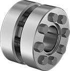
Support the weight of a motor and transfer torque to another shaft at the same time with these couplings. Often used to hang motors from conveyor belts and other driven equipment, or to connect long sections of shafts, these couplings eliminate the need for support brackets. Use a torque arm to prevent hanging motors from spinning.
The clamping screws on the coupling face squeeze two outer collars against an inner ring, pressing it tight against shafts to lock them together. This ring-locking mechanism leaves no room for backlash, meaning that all of the turning force created by the motor is passed on to the second shaft. These couplings grip shafts of any shape, so you can install them onto existing keyways and splines without using a key.
To install these couplings, use a torque wrench to tighten each screw to the fastener tightening torque listed for each coupling size. To remove, gradually loosen each screw in sequence until you can slide the coupling on the shaft. Warning: Do not remove any clamping screws from the coupling until the outer collars are separated from the inner ring. The ring is under tension, and a sudden release of the collars can cause serious injury.
Overhung load capacity is the amount of downward force that a coupling can withstand from a motor or other object that it is supporting. To calculate the overhung load, measure the distance from the center of the coupling to the center of gravity of the motor. Multiply that distance by the combined weight of the motor and the portion of the shaft between the coupling and the motor. Do not exceed the overhung load capacity for a coupling.
![]() For technical drawings and 3-D models, click on a part number.
For technical drawings and 3-D models, click on a part number.
| For Shaft Dia. | Overall Lg. | OD | Max. Speed, rpm | Max. Torque, in.-lbs. | Fastener Tightening Torque, in.-lbs. | Overhung Load Cap., in.-lbs. | For Motion Type | Each | |
Steel | |||||||||
|---|---|---|---|---|---|---|---|---|---|
| 2 1/4" | 3 1/16" | 4 3/4" | 7,500 | 44,135 | 264 | 11,030 | Forward/Reverse, Start/Stop, Continuous | 0000000 | 0000000 |