Filter by
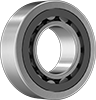
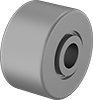
Roller Bearing Type
Shaft Diameter
For Load Direction


Bearing Type
Width
Dynamic Radial Load Capacity


ID
Roller Diameter
Maximum Rotation Speed
Static Radial Load Capacity
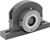
Bearing Construction


Mounted Bearing Type
DFARS Specialty Metals
Export Control Classification Number (ECCN)
Power Transmission