


Filter by
System of Measurement
Pressure Set Point
Pipe Size
Connects To
Maximum Switching Current @ Voltage
Connection Material
Measurement Unit
Maximum Input Pressure
Switch Starting Position
Wire Connection

Thread Type
DFARS Specialty Metals
Export Control Classification Number (ECCN)
REACH
RoHS
U.S.–Mexico–Canada Agreement (USMCA) Qualifying
Conduit Trade Size
Electrical Connection
Finish
Housing Finish
Housing Material
Hazardous Location Differential Pressure Switches for Liquids
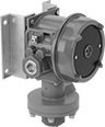 |
Tested and verified by UL and C-UL for use where explosive dust or gas are present, these switches have an explosion-proof enclosure that meets NEMA 7 and 9 standards for hazardous locations. They are often used to indicate a filter is clogged in a pump or cooling system. When the differential pressure reaches your setpoint, these switches can turn equipment on and off, activate automated controls, or signal alarms. They are single pole, double throw (SPDT) and can be installed to turn one circuit from off to on or from on to off.
In addition to being UL and C-UL listed, these switches are CE marked, so they also meet European safety standards. All switches are IP and NEMA rated for use outdoors and to protect against some corrosion, dust, and washdowns.
Pressure Set Point Range | Approx. Difference Between Set Point and Reset Point | Max. Input Pressure, psi | Accuracy | Max. Switching Current @ Voltage | Process Temp. Range, ° F | Connection Material | For Use With | Enclosure Rating | Hazardous Location Rating | Each | |||
|---|---|---|---|---|---|---|---|---|---|---|---|---|---|
Screw-Terminal Wire Connection | |||||||||||||
1/4 NPT Female Pipe Connection | |||||||||||||
| 5 in. H₂O to 80 in. H₂O | 2.5 in. H₂O | 225 | ±0.5% | 15 amp @ 125V AC 15 amp @ 250V AC 15 amp @ 480V AC 2 amp @ 30V DC 1 amp @ 48V DC 500 mA @ 125V DC | -10 to 200 | Aluminum | Diesel Fuel, Gasoline, Petroleum-Based Hydraulic Oil, Water | NEMA 4X, NEMA 7, NEMA 9, IP66 | NEC Class I Divisions 1, 2 Groups B, C, D; NEC Class II Divisions 1, 2 Groups E, F, G | 5214N11 | 0000000 | ||
| 2 psi to 20 psi | 0.2 psi | 225 | ±0.5% | 15 amp @ 125V AC 15 amp @ 250V AC 15 amp @ 480V AC 2 amp @ 30V DC 1 amp @ 48V DC 500 mA @ 125V DC | -10 to 200 | Aluminum | Diesel Fuel, Gasoline, Petroleum-Based Hydraulic Oil, Water | NEMA 4X, NEMA 7, NEMA 9, IP66 | NEC Class I Divisions 1, 2 Groups B, C, D; NEC Class II Divisions 1, 2 Groups E, F, G | 5214N12 | 000000 | ||
| 3 psi to 30 psi | 0.25 psi | 225 | ±0.5% | 15 amp @ 125V AC 15 amp @ 250V AC 15 amp @ 480V AC 2 amp @ 30V DC 1 amp @ 48V DC 500 mA @ 125V DC | -10 to 200 | Aluminum | Diesel Fuel, Gasoline, Petroleum-Based Hydraulic Oil, Water | NEMA 4X, NEMA 7, NEMA 9, IP66 | NEC Class I Divisions 1, 2 Groups B, C, D; NEC Class II Divisions 1, 2 Groups E, F, G | 5214N13 | 000000 | ||
| 10 psi to 100 psi | 0.6 psi | 225 | ±0.5% | 15 amp @ 125V AC 15 amp @ 250V AC 15 amp @ 480V AC 2 amp @ 30V DC 1 amp @ 48V DC 500 mA @ 125V DC | -10 to 200 | Aluminum | Diesel Fuel, Gasoline, Petroleum-Based Hydraulic Oil, Water | NEMA 4X, NEMA 7, NEMA 9, IP66 | NEC Class I Divisions 1, 2 Groups B, C, D; NEC Class II Divisions 1, 2 Groups E, F, G | 5214N14 | 000000 | ||
