


About Pressure Transmitters
More
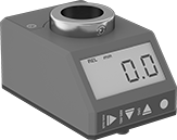
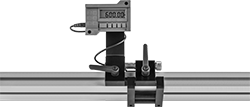
Digital Position Indicators
More customizable than standard indicators, these digital indicators have programmable features that help you adapt them to your application. Like other indicators, they track your machine component as it moves along a rotating spindle, lead screw, or other threaded shaft, which helps you adjust machinery with speed and precision. This saves time and prevents errors on process lines that you constantly adapt for different products, such as packaging lines.
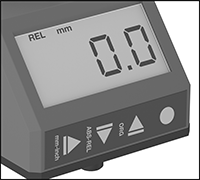
Program the number you want added per revolution—you can use these indicators as a reference point or as a true measure of distance. To measure distance, match the indicator’s count per revolution to your lead screw’s threads per inch or thread pitch. You can adjust them to count from their original position or from their most recent stopping point, which is useful for repeating moves. They also have settings to work with clockwise and counterclockwise rotation, as well as vertical and horizontal shafts.
Rated IP67, all are sealed against dust and water, even if briefly submerged. They meet IEC 61326-1, which is an international standard for electromagnetic immunity and emissions.
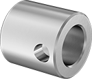
Add shaft reducer bushings to adapt indicators to fit small diameter shafts. Stainless steel bushings are more corrosion resistant than black-oxide steel bushings, so they’re better in humid locations.
![]() For technical drawings and 3-D models, click on a part number.
For technical drawings and 3-D models, click on a part number.
Overall | |||||||||||||
|---|---|---|---|---|---|---|---|---|---|---|---|---|---|
| No. of Digits | Max. Speed, rpm | Resettable | Counting Direction (Shaft Rotation Direction) | Ht. | Wd. | Dp. | Housing Material | Color | Batteries Included | Temp. Range, °F | Environmental Rating | Each | |
For 3/4" Shaft Dia. | |||||||||||||
For Horizontal and Vertical Shafts | |||||||||||||
| 6 | 1,000 | Yes | Up and Down (Clockwise and Counterclockwise) | 2.9" | 1.9" | 1.6" | Plastic | Orange | Yes | 32° to 120° | IP67 | 0000000 | 0000000 |
For 20mm Shaft Dia. | |||||||||||||
For Horizontal and Vertical Shafts | |||||||||||||
| 6 | 1,000 | Yes | Up and Down (Clockwise and Counterclockwise) | 2.9" | 1.9" | 1.6" | Plastic | Orange | Yes | 32° to 120° | IP67 | 0000000 | 000000 |
Black-Oxide Steel | Stainless Steel | ||||||
|---|---|---|---|---|---|---|---|
| For Shaft Dia. | OD | Length | Set Screw Included | Each | Each | ||
| 1/4" | 3/4" | 1" | Yes | 0000000 | 000000 | 000000 | 00 |
| 3/8" | 3/4" | 1" | Yes | 0000000 | 00000 | 0000000 | 000000 |
| 1/2" | 3/4" | 1" | Yes | 0000000 | 00000 | 0000000 | 00000 |
| 5/8" | 3/4" | 1" | Yes | 0000000 | 00000 | 0000000 | 00000 |
| 12mm | 20mm | 20mm | Yes | 0000000 | 00000 | 0000000 | 00000 |
| 14mm | 20mm | 20mm | Yes | 0000000 | 00000 | 0000000 | 00000 |
| 15mm | 20mm | 20mm | Yes | 0000000 | 00000 | 0000000 | 00000 |
| 16mm | 20mm | 20mm | Yes | 0000000 | 00000 | 0000000 | 00000 |
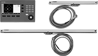
Linear Scales with Digital Readout
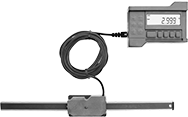
This digital readout (DRO) system displays precise positioning on one axis. For use with machines that perform dry machining and cutting applications, such as table saws, band saws, planers, and drill presses. These scales have zero-position memory, also known as absolute (ABS) positioning, which retains the measuring position when the scale is off. A zero-set button lets you start measuring at any point.
Measuring Range | Measuring Increments | Accuracy | Overall | Mount. | ||||||||||
|---|---|---|---|---|---|---|---|---|---|---|---|---|---|---|
| Inch | Metric | Inch | Metric, mm | Inch | Metric, mm | Lg. | Wd. | Material | Power Source | Batteries Included | No. of Holes | Hardware Included | Each | |
| 0"-10" | 0-250mm | 0.001" | 0.01 | ±0.002" | ±0.05 | 14 1/4" | 3/4" | Aluminum | Battery | Yes | 1 | Yes | 0000000 | 0000000 |
| 0"-18" | 0-450mm | 0.001" | 0.01 | ±0.003" | ±0.070 | 22 1/4" | 3/4" | Aluminum | Battery | Yes | 1 | Yes | 0000000 | 000000 |
| 0"-52" | 0-1.3m | 0.001" | 0.01 | ±0.008" | ±0.2 | 56" | 2" | Aluminum | Battery | Yes | 10 | Yes | 0000000 | 000000 |
| 0"-96" | 0-2.4m | 0.001" | 0.01 | ±0.008" | ±0.2 | 100" | 2" | Aluminum | Battery | Yes | 14 | Yes | 0000000 | 00000000 |
| Replacement 3-Volt Lithium Battery (Pkg. of 1) | 0000000 | 00000 |
Linear Scales with Digital Readout and Fence for Saws
Install a digital readout (DRO) stop and fence system onto the setup for your miter, chop, or radial arm saw. It displays measurements on one axis, allowing you to cut pieces up to 94" with high precision.
Measuring Range | Measuring Increments | Accuracy | Overall | |||||||||||
|---|---|---|---|---|---|---|---|---|---|---|---|---|---|---|
| Inch | Metric, mm | Inch | Metric, mm | Fractional Increments | Inch | Metric, mm | For Axis | Lg. | Wd. | Power Source | Batteries Included | Mount. Hardware Included | Each | |
| 0"-94" | 0-2,400 | 0.001" | 0.01 | 1/64" | ±0.01" | ±0.25 | X | 100" | 8.38" | Battery | Yes | Yes | 0000000 | 000000000 |
| Replacement 3-Volt Lithium Battery (Pkg. of 1) | 0000000 | Pkg. | 00000 |
Linear Scales with Digital Readout for Milling Machines
Improve the accuracy of your manual milling machine when you retrofit it with one of these digital readout (DRO) systems. They measure and display precise tool positioning on two axes.
Measuring Range | Measuring Increments | Accuracy | Scale Lg. | Scale Wd. | No. of Mounting Holes | |||||||||||||
|---|---|---|---|---|---|---|---|---|---|---|---|---|---|---|---|---|---|---|
| X-Axis | Y-Axis | X-Axis | Y-Axis | X-Axis | Y-Axis | X-Axis | Y-Axis | X-Axis | Y-Axis | Overall Lg. | Power Source | Electrical Connection Type | Voltage | X-Axis | Y-Axis | Mount. Hardware Included | Each | |
| 0"-32" | 0"-13" | 0.0002" | 0.0002" | ±0.0002" | ±0.0002" | 38 3/8" | 19 3/8" | 1 7/8" | 7/16" | 38 3/8" | Electric | Hardwire | 5.1V DC | 2 | 2 | Yes | 0000000 | 000000000 |
| 0"-35" | 0"-13" | 0.0002" | 0.0002" | ±0.0002" | ±0.0002" | 41 3/8" | 19 3/8" | 1 7/8" | 7/16" | 41 3/8" | Electric | Hardwire | 5.1V DC | 2 | 2 | Yes | 0000000 | 00000000 |
| 0"-36" | 0"-13" | 0.0002" | 0.0002" | ±0.0002" | ±0.0002" | 42 3/8" | 19 3/8" | 1 7/8" | 7/16" | 42 3/8" | Electric | Hardwire | 5.1V DC | 2 | 2 | Yes | 0000000 | 00000000 |
Linear Scales with Digital Readout for Lathes
Mount one of these digital readout (DRO) systems onto your manual lathe to increase its accuracy. They measure and display precise tool positioning on two axes.
Measuring Range | Measuring Increments | Accuracy | Scale Lg. | Scale Wd. | No. of Mount. Holes | ||||||||||||
|---|---|---|---|---|---|---|---|---|---|---|---|---|---|---|---|---|---|
| X-Axis | Z-Axis | X-Axis | Z-Axis | X-Axis | Z-Axis | X-Axis | Z-Axis | X-Axis | Z-Axis | Power Source | Electrical Connection Type | Voltage | X-Axis | Z-Axis | Mount. Hardware Included | Each | |
| 0"-6" | 0"-20 | 0.00004" | 0.00004" | ±0.0001" | ±0.0002" | 10 21/32" | 26 3/8" | 1 3/16" | 1 7/8" | Electric | Hardwire | 5.1V DC | 2 | 2 | Yes | 0000000 | 000000000 |
| 0"-8" | 0"-40 | 0.0002" | 0.0002" | ±0.0002" | ±0.0002" | 12 21/32" | 46 3/8" | 1 3/16" | 1 7/8" | Electric | Hardwire | 5.1V DC | 2 | 2 | Yes | 0000000 | 00000000 |
| 0"-10" | 0"-40 | 0.0002" | 0.0002" | ±0.0002" | ±0.0002" | 14 21/32" | 46 3/8" | 1 3/16" | 1 7/8" | Electric | Hardwire | 5.1V DC | 2 | 2 | Yes | 0000000 | 00000000 |
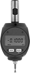
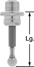
Machine Tool Indicators
Find the edge of a workpiece, align your setup, and inspect parts with one tool. Once installed in your milling machine spindle, these indicators can measure in three axes.
LCD indicator is IP64 rated for protection from dust and splashing water. It has zero-position memory, also known as absolute (ABS) positioning, which saves the measuring position when the sensor is off. A zero-set button lets you start measuring at any point.
Machine Tool Indicators | |||||||||||||||||
|---|---|---|---|---|---|---|---|---|---|---|---|---|---|---|---|---|---|
Measuring | Contact Point | Mounting Shank | Replacement Batteries | ||||||||||||||
| Range | Increments | Accuracy | Dial Dia. | Head Dia. | Lg. | Mounting Thread Size | Mounting Thread Pitch, mm | Material | Overall Lg. | Dia. | Lg. | Batteries Included | Environmental Rating | Each | Pkg. | ||
| 0"-0.15" | 0.00005" | ±0.0002" | 2.6" | 0.2" | 1" | M3 | 0.5 | Stainless Steel | 6.37" | 3/4" | 2" | Yes | IP64 | 0000000 | 000000000 | 0000000 | 00000 |
Digital Angle Indicators with Calibration Certificate
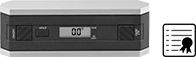
These angle indicators come with a calibration certificate that's traceable to NIST and includes the test measurements that confirm accuracy. The display shows highly accurate angle, level, and tilt measurements. They come set at true 0°, but you can choose an alternate zero point with the push of a button. Another button will freeze the reading on the display. Indicators have machined leveling surfaces, a V-groove for stability on curved surfaces, and two 6-32 threaded holes for mounting.
Angle indicator with an RS-232C computer connection can be used for ASCII output.
Connection | O'all | Mount. Holes | |||||||||||||||
|---|---|---|---|---|---|---|---|---|---|---|---|---|---|---|---|---|---|
| Angle Measuring Range | Accuracy | O'all Accuracy | No. of Measuring Quadrants | Quadrant Angle Measuring Range | Numeric Increments | Type | Industry Designation | Lg. | Wd. | Ht. | Material | Display Type | No. of | Thread Size | Batteries Included | Each | |
| 0°-360° | ±0.10° @ 0°-10° | ±0.2° | 4 | 0°-90° | 0.1° | __ | __ | 6" | 1 1/4" | 2" | Aluminum | LCD | 2 | 6-32 | Yes | 00000000 | 0000000 |
| 0°-360° | ±0.05° @ 0°-10° | ±0.2° | 4 | 0°-90° | 0.01° | Computer | RS-232C | 6" | 1 1/4" | 2" | Aluminum | LCD | 2 | 6-32 | Yes | 00000000 | 000000 |
Digital Angle Indicators with Laser
Align guide rails or lay pipe at specific angles from a flat surface. The laser light is red and is best viewed indoors. The display shows the precise angle of the beam and rotates for overhead measurements. The audible level indicator tells you when the tool is level and plumb.
Laser | O'all | |||||||||||||
|---|---|---|---|---|---|---|---|---|---|---|---|---|---|---|
| Angle Measuring Range | Accuracy | No. of Measuring Quadrants | Quadrant Angle Measuring Range | Accuracy | Range | Dot Size | Lg. | Wd. | Ht. | Mount Type | Batteries Included | Features | Each | |
| 0°-360° | ±0.2° | 4 | 0°-90° | ±1/8" @ 50 ft. | 0-200 ft. | 1/4" @ 50 ft. | 10 1/2" | 1 1/4" | 2 1/4" | Screw On, Magnetic Base | Yes | Audible Level Indicator, Backlit Display | 0000000 | 0000000 |
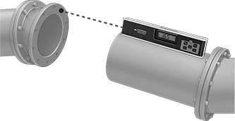
Digital Angle Indicators
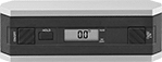
These angle indicators display highly accurate angle, level, and tilt measurements. They come set at true 0°, but you can choose an alternate zero point with the push of a button. Another button will freeze the reading on the display. Indicators have machined leveling surfaces, a V-groove for stability on curved surfaces, and two 6-32 threaded holes for mounting.
Angle indicator with an RS-232 computer connection can be used for ASCII output.
Connection | O'all | Mount. Holes | |||||||||||||||
|---|---|---|---|---|---|---|---|---|---|---|---|---|---|---|---|---|---|
| Angle Measuring Range | Accuracy | O'all Accuracy | No. of Measuring Quadrants | Quadrant Angle Measuring Range | Numeric Increments | Type | Industry Designation | Lg. | Wd. | Ht. | Material | Display Type | No. of | Thread Size | Batteries Included | Each | |
| 0°-360° | ±0.10° @ 0°-10° | ±0.2° | 4 | 0°-90° | 0.1° | __ | __ | 6" | 1 1/4" | 2" | Aluminum | LCD | 2 | 6-32 | Yes | 00000000 | 0000000 |
| 0°-360° | ±0.05° @ 0°-10° | ±0.2° | 4 | 0°-90° | 0.01° | Computer | RS-232 | 6" | 1 1/4" | 2" | Aluminum | LCD | 2 | 6-32 | Yes | 00000000 | 000000 |
Digital Angle Indicators with Pitch Measurement
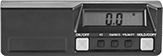
The LCD on this digital angle indicator shows angle in degrees and percent of slope. The display inverts when you turn it upside down.
Overall | |||||||||||
|---|---|---|---|---|---|---|---|---|---|---|---|
| Angle Measuring Range | Accuracy | Numeric Increments | Lg. | Wd. | Ht. | Material | Color | Display Type | Batteries Included | Each | |
| 0°-360° | ±0.1° | 0.1° | 6 5/8" | 1 3/8" | 2 1/8" | Plastic | Black | LCD | Yes | 00000000 | 0000000 |
Pressure Transmitters for Compressed Air
- For Use With: Air, Argon, Nitrogen
- Accuracy: ±0.2%
- Connection: See table
- Housing Material: Polybutylene Plastic
- Connection Material: Nickel-Plated Brass
- Temperature Range: 25° to 120° F
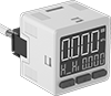
With a pressure range common to most compressed air systems, use these transmitters to monitor your system's air pressure. Also known as transducers, these transmitters convert pressure to an electrical signal that can be interpreted by receiving devices such as remote displays and motor speed controls. They can also connect to a programmable logic controller (PLC) with two digital PNP switch outputs, so you can activate automated controls or alarms when a set pressure is reached. They have a digital display with buttons to change settings.
For your receiving device to interpret the signal from the transmitter, you will need to calibrate it for the transmitter's pressure range and output signal. As pressure increases, the output signal from the transmitter will increase. Transmitters will only provide accurate readings within the rated pressure range.
UL and C-UL recognized components, CSA certified, and CE marked, they meet American, Canadian, and European safety standards.
Transmitters with current output connect using two wires. The same wire is used to send a signal to the receiver and to power the transmitter. Current doesn’t lose signal over long distances and isn’t affected by electrical interference from other devices.
Transmitters with voltage output connect using three wires—two wires into the power supply and a separate wire that sends a signal to the receiver. The receiver and the transmitter share a common ground wire back to the power supply.
Add a panel-mounting bracket (sold separately) to mount these switches to a control panel for easy viewing and adjusting.
![]() For technical drawings and 3-D models, click on a part number.
For technical drawings and 3-D models, click on a part number.
Analog Transmitter Output | Digital Switch Output | ||||||||||||
|---|---|---|---|---|---|---|---|---|---|---|---|---|---|
| Signal | No. of | Signal Type | No. of | Pressure Range, psi | Maximum Continuous Pressure, psi | Maximum Short-Term Pressure, psi | Setpoint Range, psi | Input Voltage | Ht. | Wd. | Environmental Rating | Each | |
Wire Leads | |||||||||||||
1/8 NPT Male Pipe Connection | |||||||||||||
| 2.4-20mA | 1 | PNP | 2 | 14.5-145 | 145 | 218 | 14.5-145 | 12-24V DC | 1 3/16" | 1 3/16" | IP40 | 0000000 | 000000 |
| 0.6-5V DC | 1 | PNP | 2 | 14.5-145 | 145 | 218 | 14.5-145 | 12-24V DC | 1 3/16" | 1 3/16" | IP40 | 0000000 | 00000 |
1/4" OD Push-to-Connect Tube Connection | |||||||||||||
| 2.4-20mA | 1 | PNP | 2 | 14.5-145 | 145 | 218 | 14.5-145 | 12-24V DC | 1 3/16" | 1 3/16" | IP40 | 0000000 | 00000 |
| 0.6-5V DC | 1 | PNP | 2 | 14.5-145 | 145 | 218 | 14.5-145 | 12-24V DC | 1 3/16" | 1 3/16" | IP40 | 0000000 | 00000 |
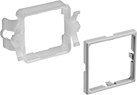
For Panel Cutout | ||||
|---|---|---|---|---|
| Ht. | Wd. | Mounting Hole Style | Each | |
| 1 7/32" | 1 7/32" | Straight | 0000000 | 00000 |
Pressure Transmitters with Digital Display
- For Use With: Air, Argon, Hydraulic Fluid, Nitrogen, Water
- Accuracy: ±0.5%
- Pipe Connection: NPT Male
- Housing Material: 304 Stainless Steel
- Connection Material: 304 Stainless Steel
- Temperature Range: -40° to 185° F
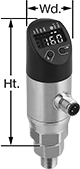
Read pressure directly at the source and send data remotely with one device. Also known as transducers, these transmitters convert pressure to an electrical signal that can be interpreted by receiving devices, such as remote displays, programmable logic controllers, and motor speed controls to monitor pressure or control equipment. As pressure increases, the output signal from the transmitter will increase. For your receiving device to interpret the signal from the transmitter, you will need to calibrate it for the pressure range and output signal of the transmitter. Transmitters will only provide accurate readings within the rated pressure range.
To change settings and receive error messages remotely from your PLC or computer, program one of the outputs to use IO Link. You need an IO-Link controller (not included) to connect to your interface.
All have an M12 plug to connect to M12 sockets. When using the analog current output they require two wires. The same wire is used to send a signal to the receiver and to power the transmitter. Current doesn’t lose signal over long distances and isn’t affected by electrical interference from other devices. These transmitters can also connect using three wires to send an analog voltage output—two wires into the power supply and a separate wire that sends a signal to the receiver. The receiver and the transmitter share a common ground wire back to the power supply. View switch wiring diagrams by selecting a part number and clicking Product Detail.
All transmitters are rated IP67 for protection from temporary submersion. UL and C-UL listed as well as CE marked, they meet strict American, Canadian, and European safety standards.
Configurable Analog Transmitter/Digital Switch Output | Configurable Digital Switch Output | |||||||||||||||
|---|---|---|---|---|---|---|---|---|---|---|---|---|---|---|---|---|
| Pressure Range, psi | Maximum Continuous Pressure, psi | Maximum Short-Term Pressure, psi | Setpoint Range, psi | Input Voltage | Pipe Size | Ht. | Wd. | No. of | Current | Voltage | Signal Type | No. of | Signal Type | Environmental Rating | Each | |
4-Pole Micro M12 Plug Connection | ||||||||||||||||
| 0-29 | 29 | 55 | 0-29 | 18-30V DC | 1/4 | 3 3/4" | 1 11/32" | 1 | 4-20mA | 0-10V DC | NPN, PNP | 1 | NPN, PNP | IP67 | 00000000 | 0000000 |
| 0-73 | 73 | 145 | 0-73 | 18-30V DC | 1/4 | 3 3/4" | 1 11/32" | 1 | 4-20mA | 0-10V DC | NPN, PNP | 1 | NPN, PNP | IP67 | 00000000 | 000000 |
| 0-145 | 145 | 290 | 0-145 | 18-30V DC | 1/4 | 3 3/4" | 1 11/32" | 1 | 4-20mA | 0-10V DC | NPN, PNP | 1 | NPN, PNP | IP67 | 00000000 | 000000 |
| 0-290 | 290 | 580 | 0-290 | 18-30V DC | 1/4 | 3 3/4" | 1 11/32" | 1 | 4-20mA | 0-10V DC | NPN, PNP | 1 | NPN, PNP | IP67 | 00000000 | 000000 |
| 0-725 | 725 | 1,450 | 0-725 | 18-30V DC | 1/4 | 3 3/4" | 1 11/32" | 1 | 4-20mA | 0-10V DC | NPN, PNP | 1 | NPN, PNP | IP67 | 00000000 | 000000 |
| 0-1,450 | 1,450 | 2,900 | 0-1,450 | 18-30V DC | 1/4 | 3 3/4" | 1 11/32" | 1 | 4-20mA | 0-10V DC | NPN, PNP | 1 | NPN, PNP | IP67 | 00000000 | 000000 |
| 0-3,625 | 3,625 | 5,800 | 0-3,625 | 18-30V DC | 1/4 | 3 3/4" | 1 11/32" | 1 | 4-20mA | 0-10V DC | NPN, PNP | 1 | NPN, PNP | IP67 | 00000000 | 000000 |
| 0-5,800 | 5,800 | 9,425 | 0-5,800 | 18-30V DC | 1/4 | 3 3/4" | 1 11/32" | 1 | 4-20mA | 0-10V DC | NPN, PNP | 1 | NPN, PNP | IP67 | 00000000 | 000000 |
| 0-8,700 | 8,700 | 14,500 | 0-8,700 | 18-30V DC | 1/4 | 3 3/4" | 1 11/32" | 1 | 4-20mA | 0-10V DC | NPN, PNP | 1 | NPN, PNP | IP67 | 00000000 | 000000 |