


Filter by
Switch Designation
Certification
Switch Type
Wire Connection

Switch Starting Position
Switch Action
Electrical Connection
DFARS Specialty Metals
U.S.–Mexico–Canada Agreement (USMCA) Qualifying
Export Control Classification Number (ECCN)
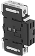
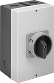
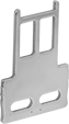
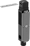
Enclosed Disconnect Switches
 |  |
Power Pole | Neutral Pole |
Cut power and keep it isolated to prevent equipment from starting up during inspection and maintenance. These switches are housed in a protective enclosure that resists denting, chipping, and cracking. Mount them to the wall when you run out of space in an electrical panel.
Use additional power poles to control more than three circuits. Add neutral poles to open and close the neutral leg of a three phase system.
Maintained Switch%20--%3e%3csvg%20version='1.1'%20id='Layer_1'%20xmlns='http://www.w3.org/2000/svg'%20xmlns:xlink='http://www.w3.org/1999/xlink'%20x='0px'%20y='0px'%20viewBox='0%200%20400%20400'%20style='enable-background:new%200%200%20400%20400;'%20xml:space='preserve'%3e%3cstyle%20type='text/css'%3e%20.st0{fill:%231A70A0;}%20.st1{opacity:0.5;}%20%3c/style%3e%3cg%3e%3cg%3e%3cpath%20class='st0'%20d='M200,56.9c38.35,0,74.4,14.93,101.51,42.05c27.11,27.11,42.05,63.17,42.05,101.51s-14.93,74.4-42.05,101.51%20S238.35,344.02,200,344.02s-74.4-14.93-101.51-42.05c-27.11-27.11-42.05-63.17-42.05-101.51s14.93-74.4,42.05-101.51%20S161.65,56.9,200,56.9%20M200,12.9C96.41,12.9,12.44,96.88,12.44,200.46c0,103.59,83.97,187.56,187.56,187.56%20c103.59,0,187.56-83.97,187.56-187.56C387.56,96.88,303.59,12.9,200,12.9L200,12.9z'/%3e%3c/g%3e%3cg%3e%3cg%20class='st1'%3e%3cpath%20class='st0'%20d='M235.49,152.24h16.15l-27.46,111.87c-1.94,7.8-2.91,12.5-2.91,14.1c0,1.82,0.58,3.29,1.73,4.41%20c1.16,1.12,2.69,1.68,4.61,1.68c5.23,0,11.78-3.85,19.63-11.55l17.22,21.34c-16.95,17.33-34.87,26-53.78,26%20c-8.37,0-15.45-1.47-21.23-4.41c-5.79-2.94-10.44-7.25-13.95-12.92c-3.51-5.67-5.27-11.18-5.27-16.53c0-1.93,0.35-5.24,1.05-9.94%20c1-6.94,2.05-12.54,3.15-16.82l15.22-62.15h-32.69l7.65-30.97C190.89,163.58,214.53,158.88,235.49,152.24z%20M230.44,80.84%20c8.24,0,14.66,2.62,19.26,7.86c4.6,5.24,6.9,11.55,6.9,18.94c0,5.46-1.42,10.7-4.25,15.73c-2.83,5.03-6.88,9.07-12.12,12.12%20c-5.24,3.05-10.33,4.57-15.24,4.57c-4.6,0-9.17-1.23-13.72-3.69c-4.55-2.46-8.02-5.78-10.43-9.95%20c-2.41-4.17-3.61-8.67-3.61-13.48c0-5.35,1.52-10.64,4.57-15.89c3.05-5.24,7.03-9.25,11.96-12.04%20C218.68,82.23,224.24,80.84,230.44,80.84z'/%3e%3c/g%3e%3cg%3e%3cpath%20class='st0'%20d='M214.08,152.24h16.15l-27.46,111.87c-1.94,7.8-2.91,12.5-2.91,14.1c0,1.82,0.58,3.29,1.73,4.41%20c1.16,1.12,2.69,1.68,4.61,1.68c5.23,0,11.78-3.85,19.63-11.55l17.22,21.34c-16.95,17.33-34.87,26-53.78,26%20c-8.37,0-15.45-1.47-21.23-4.41c-5.79-2.94-10.44-7.25-13.95-12.92c-3.51-5.67-5.27-11.18-5.27-16.53c0-1.93,0.35-5.24,1.05-9.94%20c1-6.94,2.05-12.54,3.15-16.82l15.22-62.15h-32.69l7.65-30.97C169.48,163.58,193.11,158.88,214.08,152.24z%20M209.03,80.84%20c8.24,0,14.66,2.62,19.26,7.86c4.6,5.24,6.9,11.55,6.9,18.94c0,5.46-1.42,10.7-4.25,15.73c-2.83,5.03-6.88,9.07-12.12,12.12%20c-5.24,3.05-10.33,4.57-15.24,4.57c-4.6,0-9.17-1.23-13.72-3.69c-4.55-2.46-8.02-5.78-10.43-9.95%20c-2.41-4.17-3.61-8.67-3.61-13.48c0-5.35,1.52-10.64,4.57-15.89c3.05-5.24,7.03-9.25,11.96-12.04%20C197.26,82.23,202.83,80.84,209.03,80.84z'/%3e%3c/g%3e%3c/g%3e%3c/g%3e%3c/svg%3e)
 |
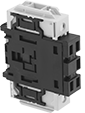
Two-Circuit Switch with Lockout |
Lockout—Switches with lockout secure in the off position with a padlock with a maximum shackle diameter of 5/16” (not included).
Photovoltaic—Photovoltaic switches can be used with photovoltaic cells which convert sunlight into electricity.
Switching | |||||||||||||||||||||||||||||||||||||||||||||||||||||||||||||||||||||||||||||||||||||||||||||||||||
|---|---|---|---|---|---|---|---|---|---|---|---|---|---|---|---|---|---|---|---|---|---|---|---|---|---|---|---|---|---|---|---|---|---|---|---|---|---|---|---|---|---|---|---|---|---|---|---|---|---|---|---|---|---|---|---|---|---|---|---|---|---|---|---|---|---|---|---|---|---|---|---|---|---|---|---|---|---|---|---|---|---|---|---|---|---|---|---|---|---|---|---|---|---|---|---|---|---|---|---|
Current, amp | Voltage, V DC | Switch Designation | Ht. | Wd. | For Max. Padlock Shackle Dia. | Wire Connection | Enclosure Rating | Certification | Each | ||||||||||||||||||||||||||||||||||||||||||||||||||||||||||||||||||||||||||||||||||||||||||
Yellow Plastic Housing with Red Actuator | |||||||||||||||||||||||||||||||||||||||||||||||||||||||||||||||||||||||||||||||||||||||||||||||||||
2 Circuits Controlled with Lockout/Photovoltaic | |||||||||||||||||||||||||||||||||||||||||||||||||||||||||||||||||||||||||||||||||||||||||||||||||||
| 32 | 800 | DPST | 11" | 7 1/2" | 5/16" | Screw Terminal | IP66 IP67 NEMA 3S NEMA 6P NEMA 12 | UL Listed, C-UL Listed, CE Marked | 6759K73 | 0000000 | |||||||||||||||||||||||||||||||||||||||||||||||||||||||||||||||||||||||||||||||||||||||||
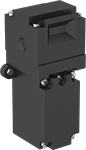
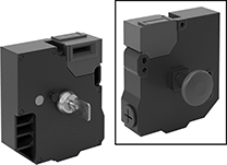
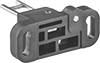
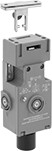
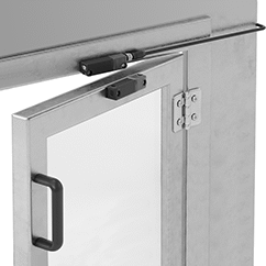
Frame-Mounted Safety Switches
 |
Key Shown Actuating from the Side |
 |  | |||
Style A | Style B | Style C | Style D | Style E |
 |  |  |  | |
Style F | Style G | Style H | Style J |
Housing | Conduit | ||||||||||||||||||||||||||||||||||||||||||||||||||||||||||||||||||||||||||||||||||||||||||||||||||
|---|---|---|---|---|---|---|---|---|---|---|---|---|---|---|---|---|---|---|---|---|---|---|---|---|---|---|---|---|---|---|---|---|---|---|---|---|---|---|---|---|---|---|---|---|---|---|---|---|---|---|---|---|---|---|---|---|---|---|---|---|---|---|---|---|---|---|---|---|---|---|---|---|---|---|---|---|---|---|---|---|---|---|---|---|---|---|---|---|---|---|---|---|---|---|---|---|---|---|---|
Style | No. of Circuits Controlled | Switch Starting Position | Switch Action | No. of Terminals | Switch Designation | Switching Current @ Voltage | Max. Voltage | Ht. | Wd. | Dp. | Trade Size | Thread Size | Thread Type | Key Included | Enclosure Rating | Each | |||||||||||||||||||||||||||||||||||||||||||||||||||||||||||||||||||||||||||||||||||
Wire Lead Connection with Positive-Force Normally Closed Contacts | |||||||||||||||||||||||||||||||||||||||||||||||||||||||||||||||||||||||||||||||||||||||||||||||||||
| A | 2 | 1 Off and 1 On | Maintained | 2 | DPST-1NO/1NC | 8 amp @ 120V AC, 4 amp @ 24V DC | 250V AC 24V DC | 3.3" | 1.2" | 1.2" | — | M16 | Metric | Yes | IP67 | 65665K25 | 0000000 | ||||||||||||||||||||||||||||||||||||||||||||||||||||||||||||||||||||||||||||||||||
Screw-Terminal Wire Connection with Positive-Force Normally Closed Contacts | |||||||||||||||||||||||||||||||||||||||||||||||||||||||||||||||||||||||||||||||||||||||||||||||||||
| B | 2 | 1 Off and 1 On | Maintained | 4 | DPST-1NO/1NC | 5 amp @ 120V AC, 2 amp @ 24V DC | 500V AC 250V DC | 3" | 1" | 1.1" | 1/2 | — | NPT | Yes | IP67, NEMA 6 | 65665K32 | 000000 | ||||||||||||||||||||||||||||||||||||||||||||||||||||||||||||||||||||||||||||||||||
| C | 3 | 1 Off and 2 On | Maintained | 3 | 3PST-1NO/2NC | 8 amp @ 120V AC, 4 amp @ 24V DC | 600V AC 250V DC | 3.5" | 2.1" | 1.2" | 1/2 | — | NPT | Yes | IP67 | 65665K15 | 000000 | ||||||||||||||||||||||||||||||||||||||||||||||||||||||||||||||||||||||||||||||||||
| C | 3 | 1 Off and 2 On | Maintained | 6 | 3PST-1NO/2NC | 4 amp @ 230V AC, 4 amp @ 24V DC | 500V AC 24V DC | 3.5" | 2" | 1.2" | — | M16 | Metric | Yes | IP67 | 65665K18 | 000000 | ||||||||||||||||||||||||||||||||||||||||||||||||||||||||||||||||||||||||||||||||||
| D | 3 | 1 Off and 2 On | Maintained | 6 | 3PST-1NO/2NC | 6 amp @ 120V AC, 0.27 amp @ 24V DC | 240V AC 250V DC | 3.8" | 1.2" | 1.2" | 1/2 | — | NPT | Yes | IP67 | 65665K16 | 00000 | ||||||||||||||||||||||||||||||||||||||||||||||||||||||||||||||||||||||||||||||||||
| E | 2 | 1 Off and 1 On | Maintained | 4 | DPST-1NO/1NC | 8 amp @ 230V AC, 5 amp @ 24V DC | 400V AC 24V DC | 4.2" | 2" | 1.6" | — | M20 | Metric | No | IP67 | 65665K43 | 00000 | ||||||||||||||||||||||||||||||||||||||||||||||||||||||||||||||||||||||||||||||||||
| E | 2 | 2 On | Maintained | 4 | DPST-NC | 8 amp @ 230V AC, 5 amp @ 24V DC | 400V AC 24V DC | 4.2" | 2" | 1.6" | — | M20 | Metric | No | IP67 | 65665K22 | 00000 | ||||||||||||||||||||||||||||||||||||||||||||||||||||||||||||||||||||||||||||||||||
| F | 2 | 1 Off and 1 On | Maintained | 4 | DPST-1NO/1NC | 2 amp @ 400V AC | 400V AC | 4.4" | 1.6" | 1.6" | — | M20 | Metric | No | IP67 | 65665K112 | 000000 | ||||||||||||||||||||||||||||||||||||||||||||||||||||||||||||||||||||||||||||||||||
| F | 2 | 1 Off and 1 On | Maintained | 4 | DPST-1NO/1NC | 2 amp @ 400V AC | 400V AC | 4.4" | 1.6" | 1.6" | 1/2 | — | BSPP | No | IP67 | 65665K111 | 000000 | ||||||||||||||||||||||||||||||||||||||||||||||||||||||||||||||||||||||||||||||||||
| F | 2 | 1 Off and 1 On | Maintained | 4 | DPST-1NO/1NC | 2 amp @ 400V AC | 400V AC | 4.4" | 1.6" | 1.6" | 1/2 | — | NPT | No | IP67 | 65665K105 | 000000 | ||||||||||||||||||||||||||||||||||||||||||||||||||||||||||||||||||||||||||||||||||
| F | 2 | 2 On | Maintained | 4 | DPST-NC | 2 amp @ 400V AC | 400V AC | 4.4" | 1.6" | 1.6" | — | M20 | Metric | No | IP67 | 65665K113 | 00000 | ||||||||||||||||||||||||||||||||||||||||||||||||||||||||||||||||||||||||||||||||||
| F | 2 | 2 On | Maintained | 4 | DPST-NC | 2 amp @ 400V AC | 400V AC | 4.4" | 1.6" | 1.6" | 1/2 | — | BSPP | No | IP67 | 65665K108 | 00000 | ||||||||||||||||||||||||||||||||||||||||||||||||||||||||||||||||||||||||||||||||||
| F | 2 | 2 On | Maintained | 4 | DPST-NC | 2 amp @ 400V AC | 400V AC | 4.4" | 1.6" | 1.6" | 1/2 | — | NPT | No | IP67 | 65665K109 | 000000 | ||||||||||||||||||||||||||||||||||||||||||||||||||||||||||||||||||||||||||||||||||
Screw-Terminal Wire Connection with Positive-Force Normally Closed Contacts and Rotating Head | |||||||||||||||||||||||||||||||||||||||||||||||||||||||||||||||||||||||||||||||||||||||||||||||||||
| D | 3 | 1 Off and 2 On | Maintained | 6 | 3PST-1NO/2NC | 10 amp @ 120V AC, 2.5 amp @ 125V DC | 240V AC 250V DC | 3.8" | 1.2" | 1.2" | — | M20 | Metric | No | IP67 | 65665K29 | 00000 | ||||||||||||||||||||||||||||||||||||||||||||||||||||||||||||||||||||||||||||||||||
| G | 3 | 1 Off and 2 On | Maintained | 6 | 3PST-1NO/2NC | 10 amp @ 230V AC, 4 amp @ 24V DC | 250V AC 24V DC | 4.3" | 1.6" | 1.4" | — | M20 | Metric | No | IP67 | 65665K19 | 000000 | ||||||||||||||||||||||||||||||||||||||||||||||||||||||||||||||||||||||||||||||||||
Screw-Terminal Wire Connection with Rotating Head | |||||||||||||||||||||||||||||||||||||||||||||||||||||||||||||||||||||||||||||||||||||||||||||||||||
| H | 4 | 2 Off and 2 On | Maintained | 8 | 4PST-2NO/2NC | 2.5 amp @ 120V AC, 1 amp @ 125V DC | 120V AC 125V DC | 7.1" | 1.5" | 1.5" | 1/2 | — | NPT | No | IP67 | 65665K31 | 000000 | ||||||||||||||||||||||||||||||||||||||||||||||||||||||||||||||||||||||||||||||||||
Screw-Terminal Wire Connection with Rear Release Button, Portable Key, and LED Status Indicator | |||||||||||||||||||||||||||||||||||||||||||||||||||||||||||||||||||||||||||||||||||||||||||||||||||
| J | 6 | 2 Off and 4 On | Maintained | 12 | 6PST-2NO/4NC | 3 amp @ 240V AC, 2.5 amp @ 250V DC | 240V AC 250V DC | 5.2" | 4.6" | 2.2" | — | M20 | Metric | Yes | IP67 | 65665K101 | 000000 | ||||||||||||||||||||||||||||||||||||||||||||||||||||||||||||||||||||||||||||||||||
 |  |  |
Straight | 90° Angle | Flexible |
O'all, mm | |||||||||||||||||||||||||||||||||||||||||||||||||||||||||||||||||||||||||||||||||||||||||||||||||||
|---|---|---|---|---|---|---|---|---|---|---|---|---|---|---|---|---|---|---|---|---|---|---|---|---|---|---|---|---|---|---|---|---|---|---|---|---|---|---|---|---|---|---|---|---|---|---|---|---|---|---|---|---|---|---|---|---|---|---|---|---|---|---|---|---|---|---|---|---|---|---|---|---|---|---|---|---|---|---|---|---|---|---|---|---|---|---|---|---|---|---|---|---|---|---|---|---|---|---|---|
For Style | Angle Range | Adjustment Direction | Lg. | Wd. | Mounting Fasteners Included | Each | |||||||||||||||||||||||||||||||||||||||||||||||||||||||||||||||||||||||||||||||||||||||||||||
Straight | |||||||||||||||||||||||||||||||||||||||||||||||||||||||||||||||||||||||||||||||||||||||||||||||||||
| E | — | — | 80 | 32 | No | 65665K27 | 000000 | ||||||||||||||||||||||||||||||||||||||||||||||||||||||||||||||||||||||||||||||||||||||||||||
| F | — | — | 53.7 | 52.4 | No | 65665K107 | 00000 | ||||||||||||||||||||||||||||||||||||||||||||||||||||||||||||||||||||||||||||||||||||||||||||
| G | — | — | 86 | 32 | No | 65665K24 | 00000 | ||||||||||||||||||||||||||||||||||||||||||||||||||||||||||||||||||||||||||||||||||||||||||||
| H | — | — | 48.5 | 35 | No | 65665K41 | 00000 | ||||||||||||||||||||||||||||||||||||||||||||||||||||||||||||||||||||||||||||||||||||||||||||
| J | — | — | 61.5 | 40 | No | 65665K102 | 00000 | ||||||||||||||||||||||||||||||||||||||||||||||||||||||||||||||||||||||||||||||||||||||||||||
90° Angle | |||||||||||||||||||||||||||||||||||||||||||||||||||||||||||||||||||||||||||||||||||||||||||||||||||
| E | — | — | 65.5 | 32 | No | 65665K28 | 00000 | ||||||||||||||||||||||||||||||||||||||||||||||||||||||||||||||||||||||||||||||||||||||||||||
| J | — | — | 45 | 40 | No | 65665K103 | 00000 | ||||||||||||||||||||||||||||||||||||||||||||||||||||||||||||||||||||||||||||||||||||||||||||
Flexible | |||||||||||||||||||||||||||||||||||||||||||||||||||||||||||||||||||||||||||||||||||||||||||||||||||
| D | 0° to 15° | Up/Down/Left/Right | 48.9 | 55 | No | 65665K167 | 00000 | ||||||||||||||||||||||||||||||||||||||||||||||||||||||||||||||||||||||||||||||||||||||||||||
| F | 0° to 18° | Left/Right | 80.7 | 40 | No | 65665K106 | 00000 | ||||||||||||||||||||||||||||||||||||||||||||||||||||||||||||||||||||||||||||||||||||||||||||
| G | 0° to 15° | Up/Down/Left/Right | 105 | 40 | No | 65665K45 | 000000 | ||||||||||||||||||||||||||||||||||||||||||||||||||||||||||||||||||||||||||||||||||||||||||||
| H | 0° to 15° | Up/Down/Left/Right | 50.4 | 55 | No | 65665K42 | 00000 | ||||||||||||||||||||||||||||||||||||||||||||||||||||||||||||||||||||||||||||||||||||||||||||
| J | 0° to 18° | Left/Right | 70 | 40 | No | 65665K104 | 00000 | ||||||||||||||||||||||||||||||||||||||||||||||||||||||||||||||||||||||||||||||||||||||||||||
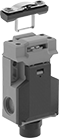
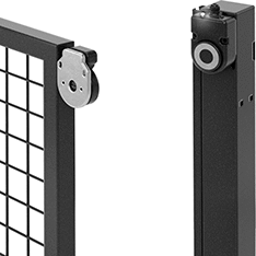
Access-Delay Frame-Mounted Safety Switches
|
Key Shown Actuating from the Side |
 |  |
Style A | Style B |
 | |
Style C |
Housing | Conduit | ||||||||||||||||||||||||||||||||||||||||||||||||||||||||||||||||||||||||||||||||||||||||||||||||||
|---|---|---|---|---|---|---|---|---|---|---|---|---|---|---|---|---|---|---|---|---|---|---|---|---|---|---|---|---|---|---|---|---|---|---|---|---|---|---|---|---|---|---|---|---|---|---|---|---|---|---|---|---|---|---|---|---|---|---|---|---|---|---|---|---|---|---|---|---|---|---|---|---|---|---|---|---|---|---|---|---|---|---|---|---|---|---|---|---|---|---|---|---|---|---|---|---|---|---|---|
Style | No. of Circuits Controlled | Switch Starting Position | Switch Action | No. of Terminals | Switch Designation | Switching Current @ Voltage | Max. Voltage | Input Voltage | Holding Force, lbf | Ht. | Wd. | Dp. | Trade Size | Thread Type | Enclosure Rating | Each | |||||||||||||||||||||||||||||||||||||||||||||||||||||||||||||||||||||||||||||||||||
Screw-Terminal Wire Connection with Positive-Force Normally Closed Contacts | |||||||||||||||||||||||||||||||||||||||||||||||||||||||||||||||||||||||||||||||||||||||||||||||||||
| A | 3 | 1 Off and 2 On | Maintained | 6 | 3PST-1NO/2NC | 5 amp @ 120V AC, 2 amp @ 24V DC | 500V AC 250V DC | 24V AC, 24V DC | 225 | 4.7" | 2.3" | 1.4" | 1/2 | NPT | IP67, NEMA 6 | 7787K61 | 0000000 | ||||||||||||||||||||||||||||||||||||||||||||||||||||||||||||||||||||||||||||||||||
| A | 3 | 1 Off and 2 On | Maintained | 6 | 3PST-1NO/2NC | 5 amp @ 120V AC, 2 amp @ 24V DC | 500V AC 250V DC | 110V AC | 225 | 4.7" | 2.3" | 1.4" | 1/2 | NPT | IP67, NEMA 6 | 7787K62 | 000000 | ||||||||||||||||||||||||||||||||||||||||||||||||||||||||||||||||||||||||||||||||||
| B | 3 | 1 Off and 2 On | Maintained | 14 | 3PST-1NO/2NC | 3 amp @ 120V AC, 2.5 amp @ 24V DC | 240V AC 250V DC | 24V DC | 225 | 3.7" | 3.5" | 1.4" | 1/2 | NPT | IP67 | 7787K64 | 000000 | ||||||||||||||||||||||||||||||||||||||||||||||||||||||||||||||||||||||||||||||||||
Screw-Terminal Wire Connection with Positive-Force Normally Closed Contacts and Rotating Head | |||||||||||||||||||||||||||||||||||||||||||||||||||||||||||||||||||||||||||||||||||||||||||||||||||
| C | 4 | 2 Off and 2 On | Maintained | 8 | 4PST-2NO/2NC | 4 amp @ 120V AC, 4 amp @ 24V DC | 240V AC 24V DC | 24V AC, 24V DC | 225 | 7.6" | 1.2" | 1.6" | 1/2 | NPT | IP67 | 7787K12 | 000000 | ||||||||||||||||||||||||||||||||||||||||||||||||||||||||||||||||||||||||||||||||||
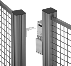
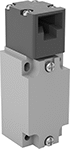
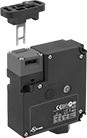
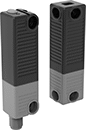
Frame-Mounted RFID Safety Switches
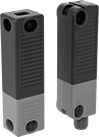
 |  |
Switch Shown Installed with LED Status Indicator | Plastic Housing |
Prevent accidental bumps or vibration from triggering these safety switches unnecessarily—a strong magnet maintains the RFID signal between the actuator and switch until it's intentionally opened. Also known as interlock switches, they automatically cut power when you open an access door, interrupting the signal, then restore power when the door is closed, and the switch and actuator meet. They're designed to mount on a frame and a door, gate, or window. Use them in many ways—from turning off a machine-operated saw when you open the protective window to powering down robotic arms when someone enters the partitioned area. The LED indicator shows that your switch is on and whether it’s actuated.
IP67 Enclosure Rating—IP67 rated switches protect against temporary submersion.
Number of Safety Outputs—The number of safety outputs, also known as output signal switching devices (OSSDs), tells you how many machines you can control. Each output has a pair of signals that shut down a single machine—if one signal fails, the other takes over as a failsafe.
Switches | Replacement Actuators | ||||||||||||||||||||||||||||||||||||||||||||||||||||||||||||||||||||||||||||||||||||||||||||||||||
|---|---|---|---|---|---|---|---|---|---|---|---|---|---|---|---|---|---|---|---|---|---|---|---|---|---|---|---|---|---|---|---|---|---|---|---|---|---|---|---|---|---|---|---|---|---|---|---|---|---|---|---|---|---|---|---|---|---|---|---|---|---|---|---|---|---|---|---|---|---|---|---|---|---|---|---|---|---|---|---|---|---|---|---|---|---|---|---|---|---|---|---|---|---|---|---|---|---|---|---|
Housing | |||||||||||||||||||||||||||||||||||||||||||||||||||||||||||||||||||||||||||||||||||||||||||||||||||
No. of Safety Outputs | Holding Force, lbf | Max. Sensing Distance, mm | Input Voltage, V DC | Current Output, mA | Signal Output | Cable Lead Lg. | Ht. | Wd. | Dp. | Mounting Fasteners Included | Features | Enclosure Rating | Each | Each | |||||||||||||||||||||||||||||||||||||||||||||||||||||||||||||||||||||||||||||||||||||
Plastic Housing | |||||||||||||||||||||||||||||||||||||||||||||||||||||||||||||||||||||||||||||||||||||||||||||||||||
With 8-Pole M12 Plug | |||||||||||||||||||||||||||||||||||||||||||||||||||||||||||||||||||||||||||||||||||||||||||||||||||
| 1 | 152 | 10 | 24 | 200 | PNP | 10" | 3.8" | 2.5" | 1.5" | Yes | Auxiliary PNP Output, LED Status Indicator, Magnetic Latch | IP67 | 8043N12 | 0000000 | 8043N13 | 0000000 | |||||||||||||||||||||||||||||||||||||||||||||||||||||||||||||||||||||||||||||||||||
 |
M12 cords connect switches to your system’s circuits.
Electrical Connection | Connection End Type | No. of Poles | Electrical Connection Coding | Face Dia. | Voltage | Current, amp | AWG | Cable OD | Cable Lead Lg., ft. | Housing Material | Enclosure Rating | Each | ||
|---|---|---|---|---|---|---|---|---|---|---|---|---|---|---|
| M12, Wire Leads | Socket | 8 | A | 0.3" | 30V AC/30V DC | 2 | 30 | 0.23" | 9.5 | Polyurethane Rubber | IP66K, IP67 | 4458N61 | 000000 |
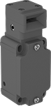
RFID Safety Switches
 |
 |
Replacement Actuator |
The convenient, modern alternative to mechanical safety switches. These RFID switches are easier to install, fit a wider range of access points, and can mount horizontally. Since they don't need a traditional key to actuate, they work even if the switch and actuator are slightly misaligned. Also known as interlock switches, they shut off power to equipment as soon as you open the barrier, which disconnects the RFID signal. These switches are often used with small machines. Find them anywhere from a CNC machine’s window to a packaging machine’s service panel. Mount the switch on the frame and the actuator on the barrier. Rated IP67 and IP69K, these switches are protected against temporary submersion and high-pressure, high-temperature washdowns.
Magnetic Latch—Switches with a magnetic latch help prevent a barrier from opening by accident, such as from light bumps and low vibrations. The magnet keeps the actuator and switch from separating.
Number of Safety Outputs—The number of safety outputs, also known as output signal switching devices (OSSDs), tells you how many machines you can control. Each output has a pair of signals that shut down a single machine—if one signal fails, the other takes over as a failsafe.
Switches | Replacement Actuators | ||||||||||||||||||||||||||||||||||||||||||||||||||||||||||||||||||||||||||||||||||||||||||||||||||
|---|---|---|---|---|---|---|---|---|---|---|---|---|---|---|---|---|---|---|---|---|---|---|---|---|---|---|---|---|---|---|---|---|---|---|---|---|---|---|---|---|---|---|---|---|---|---|---|---|---|---|---|---|---|---|---|---|---|---|---|---|---|---|---|---|---|---|---|---|---|---|---|---|---|---|---|---|---|---|---|---|---|---|---|---|---|---|---|---|---|---|---|---|---|---|---|---|---|---|---|
Housing | Mounting | ||||||||||||||||||||||||||||||||||||||||||||||||||||||||||||||||||||||||||||||||||||||||||||||||||
No. of Safety Outputs | Holding Force, lbf | Max. Sensing Distance, mm | Input Voltage, V DC | Current Output, mA | Signal Output | Ht. | Wd. | Dp. | Fasteners Included | No. of Slots | Slot Lg. | Slot Wd. | Features | Enclosure Rating | Each | Each | |||||||||||||||||||||||||||||||||||||||||||||||||||||||||||||||||||||||||||||||||||
Plastic Housing | |||||||||||||||||||||||||||||||||||||||||||||||||||||||||||||||||||||||||||||||||||||||||||||||||||
With 8-Pole M12 Plug | |||||||||||||||||||||||||||||||||||||||||||||||||||||||||||||||||||||||||||||||||||||||||||||||||||
| 1 | — | 12 | 24 | 250 | PNP | 3.6" | 0.9" | 1" | No | 2 | 0.18" | 0.26" | Auxiliary PNP Output | IP65, IP67, IP69K | 8049N101 | 0000000 | 8049N12 | 000000 | |||||||||||||||||||||||||||||||||||||||||||||||||||||||||||||||||||||||||||||||||
| 1 | 4 | 12 | 24 | 250 | PNP | 3.6" | 0.9" | 1" | No | 2 | 0.18" | 0.26" | Auxiliary PNP Output, Magnetic Latch | IP65, IP67, IP69K | 8049N102 | 000000 | 8049N14 | 00000 | |||||||||||||||||||||||||||||||||||||||||||||||||||||||||||||||||||||||||||||||||
M12 cords connect switches to your system’s circuits.
Cord | ||||||||||||||
|---|---|---|---|---|---|---|---|---|---|---|---|---|---|---|
Electrical Connection | Connection End Type | No. of Poles | Electrical Connection Coding | Face Dia. | Lg., ft. | Voltage | Current, amp | AWG | OD | Insulation Material | Enclosure Rating | Each | ||
| M12 | Plug, Socket | 8 | A | 0.3" | 3 | 30V AC/30V DC | 2 | 22 | 0.22" | PVC | IP66K, IP67 | 5059N39 | 0000000 | |
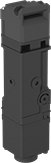
Tamper-Resistant RFID Safety Switches
 |
Replacement Actuator |
 |
Block access to machinery while it's running. These safety switches cut power when their signal disconnects, shutting off equipment as you open machine guards. They link to a single actuator, so no other RFID tag or card can interfere. The unique RFID code means that once the power is cut, no one can bypass the switch and restart equipment while the guard is open.
These switches are often used with small machines where there’s no risk of the barrier closing on its own. Find them anywhere from a CNC machine’s window to a machine-operated saw’s service panel. Mount the switch on the frame and the actuator on the barrier. They're also known as interlock switches. Rated IP67 and IP69K, these switches are protected against temporary submersion and high-pressure, high-temperature washdowns.
Magnetic Latch—Switches with a magnetic latch prevent guards from opening by accident, such as from light bumps and low vibrations.
Number of Safety Outputs—The number of safety outputs, also known as output signal switching devices (OSSDs), tells you how many machines you can control. Each output has a pair of signals that shut down a single machine—if one signal fails, the other takes over as a failsafe.
Switches | Replacement Actuators | ||||||||||||||||||||||||||||||||||||||||||||||||||||||||||||||||||||||||||||||||||||||||||||||||||
|---|---|---|---|---|---|---|---|---|---|---|---|---|---|---|---|---|---|---|---|---|---|---|---|---|---|---|---|---|---|---|---|---|---|---|---|---|---|---|---|---|---|---|---|---|---|---|---|---|---|---|---|---|---|---|---|---|---|---|---|---|---|---|---|---|---|---|---|---|---|---|---|---|---|---|---|---|---|---|---|---|---|---|---|---|---|---|---|---|---|---|---|---|---|---|---|---|---|---|---|
Housing | Mounting | ||||||||||||||||||||||||||||||||||||||||||||||||||||||||||||||||||||||||||||||||||||||||||||||||||
No. of Safety Outputs | Holding Force, lbf | Max. Sensing Distance, mm | Input Voltage, V DC | Current Output, mA | Signal Output | Ht. | Wd. | Dp. | Fasteners Included | No. of Slots | Slot Lg. | Slot Wd. | Features | Enclosure Rating | Each | Each | |||||||||||||||||||||||||||||||||||||||||||||||||||||||||||||||||||||||||||||||||||
Plastic Housing | |||||||||||||||||||||||||||||||||||||||||||||||||||||||||||||||||||||||||||||||||||||||||||||||||||
With 8-Pole M12 Plug | |||||||||||||||||||||||||||||||||||||||||||||||||||||||||||||||||||||||||||||||||||||||||||||||||||
| 1 | — | 12 | 24 | 250 | PNP | 3.6" | 0.9" | 1" | No | 2 | 0.18" | 0.26" | Auxiliary PNP Output, Unique RFID Code | IP65, IP67, IP69K | 7681N111 | 0000000 | 7681N11 | 000000 | |||||||||||||||||||||||||||||||||||||||||||||||||||||||||||||||||||||||||||||||||
| 1 | 4 | 12 | 24 | 250 | PNP | 3.6" | 0.9" | 1" | No | 2 | 0.18" | 0.26" | Auxiliary PNP Output, Magnetic Latch, Unique RFID Code | IP65, IP67, IP69K | 7681N112 | 000000 | 7681N12 | 00000 | |||||||||||||||||||||||||||||||||||||||||||||||||||||||||||||||||||||||||||||||||
M12 cords connect switches to your system’s circuits.
Cord | ||||||||||||||
|---|---|---|---|---|---|---|---|---|---|---|---|---|---|---|
Electrical Connection | Connection End Type | No. of Poles | Electrical Connection Coding | Face Dia. | Lg., ft. | Voltage | Current, amp | AWG | OD | Insulation Material | Enclosure Rating | Each | ||
| M12 | Plug, Socket | 8 | A | 0.3" | 3 | 30V AC/30V DC | 2 | 22 | 0.22" | PVC | IP66K, IP67 | 5059N39 | 0000000 | |
