Filter by
System of Measurement
Switching Current
Switching Voltage
Horsepower @ Switching Voltage
Switch Designation
Switch Type
Switch Action
Certification
Mounting Location
Export Control Classification Number (ECCN)
DFARS Specialty Metals
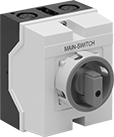
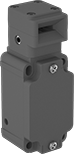
Panel-Mount Compact Disconnect Switches
Maintained Switch%20--%3e%3csvg%20version='1.1'%20id='Layer_1'%20xmlns='http://www.w3.org/2000/svg'%20xmlns:xlink='http://www.w3.org/1999/xlink'%20x='0px'%20y='0px'%20viewBox='0%200%20400%20400'%20style='enable-background:new%200%200%20400%20400;'%20xml:space='preserve'%3e%3cstyle%20type='text/css'%3e%20.st0{fill:%231A70A0;}%20.st1{opacity:0.5;}%20%3c/style%3e%3cg%3e%3cg%3e%3cpath%20class='st0'%20d='M200,56.9c38.35,0,74.4,14.93,101.51,42.05c27.11,27.11,42.05,63.17,42.05,101.51s-14.93,74.4-42.05,101.51%20S238.35,344.02,200,344.02s-74.4-14.93-101.51-42.05c-27.11-27.11-42.05-63.17-42.05-101.51s14.93-74.4,42.05-101.51%20S161.65,56.9,200,56.9%20M200,12.9C96.41,12.9,12.44,96.88,12.44,200.46c0,103.59,83.97,187.56,187.56,187.56%20c103.59,0,187.56-83.97,187.56-187.56C387.56,96.88,303.59,12.9,200,12.9L200,12.9z'/%3e%3c/g%3e%3cg%3e%3cg%20class='st1'%3e%3cpath%20class='st0'%20d='M235.49,152.24h16.15l-27.46,111.87c-1.94,7.8-2.91,12.5-2.91,14.1c0,1.82,0.58,3.29,1.73,4.41%20c1.16,1.12,2.69,1.68,4.61,1.68c5.23,0,11.78-3.85,19.63-11.55l17.22,21.34c-16.95,17.33-34.87,26-53.78,26%20c-8.37,0-15.45-1.47-21.23-4.41c-5.79-2.94-10.44-7.25-13.95-12.92c-3.51-5.67-5.27-11.18-5.27-16.53c0-1.93,0.35-5.24,1.05-9.94%20c1-6.94,2.05-12.54,3.15-16.82l15.22-62.15h-32.69l7.65-30.97C190.89,163.58,214.53,158.88,235.49,152.24z%20M230.44,80.84%20c8.24,0,14.66,2.62,19.26,7.86c4.6,5.24,6.9,11.55,6.9,18.94c0,5.46-1.42,10.7-4.25,15.73c-2.83,5.03-6.88,9.07-12.12,12.12%20c-5.24,3.05-10.33,4.57-15.24,4.57c-4.6,0-9.17-1.23-13.72-3.69c-4.55-2.46-8.02-5.78-10.43-9.95%20c-2.41-4.17-3.61-8.67-3.61-13.48c0-5.35,1.52-10.64,4.57-15.89c3.05-5.24,7.03-9.25,11.96-12.04%20C218.68,82.23,224.24,80.84,230.44,80.84z'/%3e%3c/g%3e%3cg%3e%3cpath%20class='st0'%20d='M214.08,152.24h16.15l-27.46,111.87c-1.94,7.8-2.91,12.5-2.91,14.1c0,1.82,0.58,3.29,1.73,4.41%20c1.16,1.12,2.69,1.68,4.61,1.68c5.23,0,11.78-3.85,19.63-11.55l17.22,21.34c-16.95,17.33-34.87,26-53.78,26%20c-8.37,0-15.45-1.47-21.23-4.41c-5.79-2.94-10.44-7.25-13.95-12.92c-3.51-5.67-5.27-11.18-5.27-16.53c0-1.93,0.35-5.24,1.05-9.94%20c1-6.94,2.05-12.54,3.15-16.82l15.22-62.15h-32.69l7.65-30.97C169.48,163.58,193.11,158.88,214.08,152.24z%20M209.03,80.84%20c8.24,0,14.66,2.62,19.26,7.86c4.6,5.24,6.9,11.55,6.9,18.94c0,5.46-1.42,10.7-4.25,15.73c-2.83,5.03-6.88,9.07-12.12,12.12%20c-5.24,3.05-10.33,4.57-15.24,4.57c-4.6,0-9.17-1.23-13.72-3.69c-4.55-2.46-8.02-5.78-10.43-9.95%20c-2.41-4.17-3.61-8.67-3.61-13.48c0-5.35,1.52-10.64,4.57-15.89c3.05-5.24,7.03-9.25,11.96-12.04%20C197.26,82.23,202.83,80.84,209.03,80.84z'/%3e%3c/g%3e%3c/g%3e%3c/g%3e%3c/svg%3e)
 |
Lockout—All switches have a lockout so you can secure them in the off position with a padlock (not included).
IP65 Enclosure Rating—They’re rated IP65 for protection from washdowns.
Switching Current @ Voltage | Switch Designation | Electrical Phase (hp) | Ht. | Wd. | Dp. Behind Panel | For Max. Padlock Shackle Dia. | Enclosure Rating | Certification | Specs. Met | Each | |||
|---|---|---|---|---|---|---|---|---|---|---|---|---|---|
Gray Plastic Housing with Black Actuator | |||||||||||||
3 Circuits Controlled with Lockout—For 3/8" Dia. Panel Cutouts | |||||||||||||
| 12 amp @ 600V AC, 16 amp @ 24V DC | 3PST | Single (1/2 hp @ 120V AC) Three (1 hp @ 120V AC) Three (3 hp @ 240V AC) | 3 1/4" | 2 1/2" | 1 13/16" | 5/16" | IP65 | UL Recognized Component | UL 508 | 65915K101 | 000000 | ||
| 16 amp @ 600V AC, 20 amp @ 24V DC | 3PST | Single (1 hp @ 120V AC) Three (2 hp @ 120V AC) Three (5 hp @ 240V AC) | 3 1/4" | 2 1/2" | 1 13/16" | 5/16" | IP65 | UL Recognized Component | UL 508 | 65915K102 | 00000 | ||
| 20 amp @ 600V AC, 25 amp @ 24V DC | 3PST | Single (1 1/2 hp @ 120V AC) Three (3 hp @ 120V AC) Three (5 hp @ 240V AC) | 3 1/4" | 2 1/2" | 1 13/16" | 5/16" | IP65 | UL Recognized Component | UL 508 | 65915K103 | 00000 | ||
| 25 amp @ 600V AC, 32 amp @ 24V DC | 3PST | Single (2 hp @ 120V AC) Three (3 hp @ 120V AC) Three (7 1/2 hp @ 240V AC) | 4" | 3 1/8" | 2" | 5/16" | IP65 | UL Recognized Component | UL 508 | 65915K104 | 000000 | ||
| 50 amp @ 600V AC, 50 amp @ 24V DC | 3PST | Single (3 hp @ 120V AC) Three (7 1/2 hp @ 120V AC) Three (15 hp @ 240V AC) | 4" | 3 1/8" | 3 3/16" | 5/16" | IP65 | UL Recognized Component | UL 508 | 65915K105 | 000000 | ||
| 63 amp @ 600V AC, 80 amp @ 24V DC | 3PST | Single (5 hp @ 120V AC) Three (10 hp @ 120V AC) Three (20 hp @ 240V AC) | 4" | 3 1/8" | 3 3/16" | 5/16" | IP65 | UL Recognized Component | UL 508 | 65915K106 | 000000 | ||
4 Circuits Controlled with Lockout—For 3/8" Dia. Panel Cutouts | |||||||||||||
| 12 amp @ 600V AC, 16 amp @ 24V DC | 4PST | Single (1/2 hp @ 120V AC) Three (1 hp @ 120V AC) Three (3 hp @ 240V AC) | 3 1/4" | 2 1/2" | 1 13/16" | 5/16" | IP65 | UL Recognized Component | UL 508 | 65915K107 | 00000 | ||
| 16 amp @ 600V AC, 20 amp @ 24V DC | 4PST | Single (1 hp @ 120V AC) Three (2 hp @ 120V AC) Three (5 hp @ 240V AC) | 3 1/4" | 2 1/2" | 1 13/16" | 5/16" | IP65 | UL Recognized Component | UL 508 | 65915K108 | 00000 | ||
| 20 amp @ 600V AC, 25 amp @ 24V DC | 4PST | Single (1 1/2 hp @ 120V AC) Three (3 hp @ 120V AC) Three (5 hp @ 240V AC) | 3 1/4" | 2 1/2" | 1 13/16" | 5/16" | IP65 | UL Recognized Component | UL 508 | 65915K109 | 00000 | ||
| 25 amp @ 600V AC, 32 amp @ 24V DC | 4PST | Single (2 hp @ 120V AC) Three (3 hp @ 120V AC) Three (7 1/2 hp @ 240V AC) | 4" | 3 1/8" | 2" | 5/16" | IP65 | UL Recognized Component | UL 508 | 65915K111 | 000000 | ||
| 50 amp @ 600V AC, 50 amp @ 24V DC | 4PST | Single (3 hp @ 120V AC) Three (7 1/2 hp @ 120V AC) Three (15 hp @ 240V AC) | 4" | 3 1/8" | 3 3/16" | 5/16" | IP65 | UL Recognized Component | UL 508 | 65915K112 | 000000 | ||
| 63 amp @ 600V AC, 80 amp @ 24V DC | 4PST | Single (5 hp @ 120V AC) Three (10 hp @ 120V AC) Three (20 hp @ 240V AC) | 4" | 3 1/8" | 3 3/16" | 5/16" | IP65 | UL Recognized Component | UL 508 | 65915K113 | 000000 | ||
Yellow Plastic Housing with Red Actuator | |||||||||||||
3 Circuits Controlled with Lockout—For 3/8" Dia. Panel Cutouts | |||||||||||||
| 12 amp @ 600V AC, 16 amp @ 24V DC | 3PST | Single (1/2 hp @ 120V AC) Three (1 hp @ 120V AC) Three (3 hp @ 240V AC) | 3 1/4" | 2 1/2" | 1 13/16" | 5/16" | IP65 | UL Recognized Component | UL 508 | 65915K11 | 00000 | ||
| 16 amp @ 600V AC, 20 amp @ 24V DC | 3PST | Single (1 hp @ 120V AC) Three (2 hp @ 120V AC) Three (5 hp @ 240V AC) | 3 1/4" | 2 1/2" | 1 13/16" | 5/16" | IP65 | UL Recognized Component | UL 508 | 65915K12 | 00000 | ||
| 20 amp @ 600V AC, 25 amp @ 24V DC | 3PST | Single (1 1/2 hp @ 120V AC) Three (3 hp @ 120V AC) Three (5 hp @ 240V AC) | 3 1/4" | 2 1/2" | 1 13/16" | 5/16" | IP65 | UL Recognized Component | UL 508 | 65915K13 | 00000 | ||
| 25 amp @ 600V AC, 32 amp @ 24V DC | 3PST | Single (2 hp @ 120V AC) Three (3 hp @ 120V AC) Three (7 1/2 hp @ 240V AC) | 4" | 3 1/8" | 2" | 5/16" | IP65 | UL Recognized Component | UL 508 | 65915K14 | 000000 | ||
| 50 amp @ 600V AC, 50 amp @ 24V DC | 3PST | Single (3 hp @ 120V AC) Three (7 1/2 hp @ 120V AC) Three (15 hp @ 240V AC) | 4" | 3 1/8" | 3 3/16" | 5/16" | IP65 | UL Recognized Component | UL 508 | 65915K15 | 000000 | ||
| 63 amp @ 600V AC, 80 amp @ 24V DC | 3PST | Single (5 hp @ 120V AC) Three (10 hp @ 120V AC) Three (20 hp @ 240V AC) | 4" | 3 1/8" | 3 3/16" | 5/16" | IP65 | UL Recognized Component | UL 508 | 65915K16 | 000000 | ||
4 Circuits Controlled with Lockout—For 3/8" Dia. Panel Cutouts | |||||||||||||
| 12 amp @ 600V AC, 16 amp @ 24V DC | 4PST | Single (1/2 hp @ 120V AC) Three (1 hp @ 120V AC) Three (3 hp @ 240V AC) | 3 1/4" | 2 1/2" | 1 13/16" | 5/16" | IP65 | UL Recognized Component | UL 508 | 65915K41 | 00000 | ||
| 16 amp @ 600V AC, 20 amp @ 24V DC | 4PST | Single (1 hp @ 120V AC) Three (2 hp @ 120V AC) Three (5 hp @ 240V AC) | 3 1/4" | 2 1/2" | 1 13/16" | 5/16" | IP65 | UL Recognized Component | UL 508 | 65915K42 | 00000 | ||
| 20 amp @ 600V AC, 25 amp @ 24V DC | 4PST | Single (1 1/2 hp @ 120V AC) Three (3 hp @ 120V AC) Three (5 hp @ 240V AC) | 3 1/4" | 2 1/2" | 1 13/16" | 5/16" | IP65 | UL Recognized Component | UL 508 | 65915K43 | 00000 | ||
| 25 amp @ 600V AC, 32 amp @ 24V DC | 4PST | Single (2 hp @ 120V AC) Three (3 hp @ 120V AC) Three (7 1/2 hp @ 240V AC) | 4" | 3 1/8" | 2" | 5/16" | IP65 | UL Recognized Component | UL 508 | 65915K44 | 000000 | ||
| 50 amp @ 600V AC, 50 amp @ 24V DC | 4PST | Single (3 hp @ 120V AC) Three (7 1/2 hp @ 120V AC) Three (15 hp @ 240V AC) | 4" | 3 1/8" | 3 3/16" | 5/16" | IP65 | UL Recognized Component | UL 508 | 65915K45 | 000000 | ||
| 63 amp @ 600V AC, 80 amp @ 24V DC | 4PST | Single (5 hp @ 120V AC) Three (10 hp @ 120V AC) Three (20 hp @ 240V AC) | 4" | 3 1/8" | 3 3/16" | 5/16" | IP65 | UL Recognized Component | UL 508 | 65915K46 | 000000 | ||
Enclosed Compact Disconnect Switches
Maintained Switch
 |
Plastic Housing—Their plastic housing protects the switch and resists denting, chipping, and cracking.
Lockout—All switches have a lockout so you can secure them in the off position with a padlock (not included).
IP65 Enclosure Rating—Rated IP65, the housing also seals out water even in frequently washed down areas.
Switching Current @ Voltage | Switch Designation | Electrical Phase (hp) | Ht. | Wd. | For Max. Padlock Shackle Dia. | Enclosure Rating | Certification | Specs. Met | Each | |||
|---|---|---|---|---|---|---|---|---|---|---|---|---|
Yellow Plastic Housing with Red Actuator | ||||||||||||
3 Circuits Controlled with Lockout | ||||||||||||
| 12 amp @ 600V AC, 16 amp @ 24V DC | 3PST | Single (1/2 hp @ 120V AC) Three (1 hp @ 120V AC) Three (3 hp @ 240V AC) | 4 3/4" | 3 13/16" | 5/16" | IP65 | UL Recognized Component, CSA Certified | UL 508 | 65915K21 | 0000000 | ||
| 16 amp @ 600V AC, 20 amp @ 24V DC | 3PST | Single (1 hp @ 120V AC) Three (2 hp @ 120V AC) Three (5 hp @ 240V AC) | 4 3/4" | 3 13/16" | 5/16" | IP65 | UL Recognized Component, CSA Certified | UL 508 | 65915K22 | 000000 | ||
| 20 amp @ 600V AC, 25 amp @ 24V DC | 3PST | Single (1 1/2 hp @ 120V AC) Three (3 hp @ 120V AC) Three (5 hp @ 240V AC) | 4 3/4" | 3 13/16" | 5/16" | IP65 | UL Recognized Component, CSA Certified | UL 508 | 65915K23 | 000000 | ||
| 25 amp @ 600V AC, 32 amp @ 24V DC | 3PST | Single (2 hp @ 120V AC) Three (3 hp @ 120V AC) Three (7 1/2 hp @ 240V AC) | 4 3/4" | 3 13/16" | 5/16" | IP65 | UL Recognized Component, CSA Certified | UL 508 | 65915K24 | 000000 | ||
| 50 amp @ 600V AC, 50 amp @ 24V DC | 3PST | Single (3 hp @ 120V AC) Three (7 1/2 hp @ 120V AC) Three (15 hp @ 240V AC) | 5 5/16" | 6 11/16" | 5/16" | IP65 | UL Recognized Component, CSA Certified | UL 508 | 65915K25 | 000000 | ||
| 63 amp @ 600V AC, 80 amp @ 24V DC | 3PST | Single (5 hp @ 120V AC) Three (10 hp @ 120V AC) Three (20 hp @ 240V AC) | 5 5/16" | 6 11/16" | 5/16" | IP65 | UL Recognized Component, CSA Certified | UL 508 | 65915K26 | 000000 | ||
4 Circuits Controlled with Lockout | ||||||||||||
| 12 amp @ 600V AC, 16 amp @ 24V DC | 4PST | Single (1/2 hp @ 120V AC) Three (1 hp @ 120V AC) Three (3 hp @ 240V AC) | 4 3/4" | 3 13/16" | 5/16" | IP65 | UL Recognized Component, CSA Certified | — | 65915K34 | 000000 | ||
| 16 amp @ 600V AC, 20 amp @ 24V DC | 4PST | Single (1 hp @ 120V AC) Three (2 hp @ 120V AC) Three (5 hp @ 240V AC) | 4 3/4" | 3 13/16" | 5/16" | IP65 | UL Recognized Component, CSA Certified | — | 65915K35 | 000000 | ||
| 20 amp @ 600V AC, 25 amp @ 24V DC | 4PST | Single (1 1/2 hp @ 120V AC) Three (3 hp @ 120V AC) Three (5 hp @ 240V AC) | 4 3/4" | 3 13/16" | 5/16" | IP65 | UL Recognized Component, CSA Certified | — | 65915K36 | 000000 | ||
| 25 amp @ 600V AC, 32 amp @ 24V DC | 4PST | Single (2 hp @ 120V AC) Three (3 hp @ 120V AC) Three (7 1/2 hp @ 240V AC) | 4 3/4" | 3 13/16" | 5/16" | IP65 | UL Recognized Component, CSA Certified | — | 65915K37 | 000000 | ||
| 50 amp @ 600V AC, 50 amp @ 24V DC | 4PST | Single (3 hp @ 120V AC) Three (7 1/2 hp @ 120V AC) Three (15 hp @ 240V AC) | 5 5/16" | 6 11/16" | 5/16" | IP65 | UL Recognized Component, CSA Certified | — | 65915K38 | 000000 | ||
| 63 amp @ 600V AC, 80 amp @ 24V DC | 4PST | Single (5 hp @ 120V AC) Three (10 hp @ 120V AC) Three (20 hp @ 240V AC) | 5 5/16" | 6 11/16" | 5/16" | IP65 | UL Recognized Component, CSA Certified | — | 65915K39 | 000000 | ||
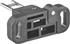
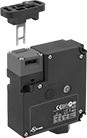
Frame-Mounted Safety Switches
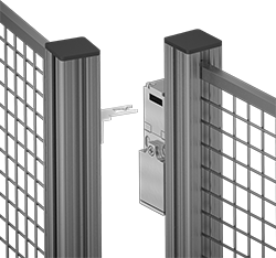 |
Key Shown Actuating from the Side |
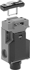 |  |  | |||
Style A | Style B | Style C | Style D | Style E | Style G |
Housing | Conduit | ||||||||||||||||||
|---|---|---|---|---|---|---|---|---|---|---|---|---|---|---|---|---|---|---|---|
Style | No. of Circuits Controlled | Switch Starting Position | Switch Action | No. of Terminals | Switch Designation | Switching Current @ Voltage | Max. Voltage | Ht. | Wd. | Dp. | Trade Size | Thread Size | Thread Type | Key Included | Enclosure Rating | Each | |||
Wire Lead Connection with Positive-Force Normally Closed Contacts | |||||||||||||||||||
| A | 2 | 1 Off and 1 On | Maintained | 2 | DPST-1NO/1NC | 8 amp @ 120V AC, 4 amp @ 24V DC | 250V AC 24V DC | 3.3" | 1.2" | 1.2" | — | M16 | Metric | Yes | IP67 | 65665K25 | 0000000 | ||
Screw-Terminal Wire Connection with Positive-Force Normally Closed Contacts | |||||||||||||||||||
| B | 2 | 1 Off and 1 On | Maintained | 4 | DPST-1NO/1NC | 5 amp @ 120V AC, 2 amp @ 24V DC | 500V AC 250V DC | 3" | 1" | 1.1" | 1/2 | — | NPT | Yes | IP67, NEMA 6 | 65665K32 | 000000 | ||
| C | 2 | 1 Off and 1 On | Maintained | 4 | DPST-1NO/1NC | 10 amp @ 120V AC, 2 amp @ 24V DC | 250V AC 24V DC | 3.6" | 2.1" | 1.3" | 1/2 | — | NPT | Yes | IP65, NEMA 4 | 65665K13 | 000000 | ||
| C | 3 | 1 Off and 2 On | Maintained | 3 | 3PST-1NO/2NC | 8 amp @ 120V AC, 4 amp @ 24V DC | 600V AC 250V DC | 3.5" | 2.1" | 1.2" | 1/2 | — | NPT | Yes | IP67 | 65665K15 | 000000 | ||
| C | 3 | 1 Off and 2 On | Maintained | 6 | 3PST-1NO/2NC | 4 amp @ 230V AC, 4 amp @ 24V DC | 500V AC 24V DC | 3.5" | 2" | 1.2" | — | M16 | Metric | Yes | IP67 | 65665K18 | 000000 | ||
| D | 3 | 1 Off and 2 On | Maintained | 6 | 3PST-1NO/2NC | 6 amp @ 120V AC, 0.27 amp @ 24V DC | 240V AC 250V DC | 3.8" | 1.2" | 1.2" | 1/2 | — | NPT | Yes | IP67 | 65665K16 | 00000 | ||
| E | 2 | 1 Off and 1 On | Maintained | 4 | DPST-1NO/1NC | 8 amp @ 230V AC, 5 amp @ 24V DC | 400V AC 24V DC | 4.2" | 2" | 1.6" | — | M20 | Metric | No | IP67 | 65665K43 | 00000 | ||
| E | 2 | 2 On | Maintained | 4 | DPST-NC | 8 amp @ 230V AC, 5 amp @ 24V DC | 400V AC 24V DC | 4.2" | 2" | 1.6" | — | M20 | Metric | No | IP67 | 65665K22 | 00000 | ||
Screw-Terminal Wire Connection with Positive-Force Normally Closed Contacts and Rotating Head | |||||||||||||||||||
| C | 3 | 1 Off and 2 On | Maintained | 6 | 3PST-1NO/2NC | 5 amp @ 120V AC, 5 amp @ 24V DC | 400V AC 400V DC | 3.5" | 2" | 1.3" | 1/2 | — | NPT | Yes | IP65 | 65665K51 | 000000 | ||
| G | 3 | 1 Off and 2 On | Maintained | 6 | 3PST-1NO/2NC | 10 amp @ 230V AC, 4 amp @ 24V DC | 250V AC 24V DC | 4.3" | 1.6" | 1.4" | — | M20 | Metric | No | IP67 | 65665K19 | 000000 | ||
 |  |  |
Straight | 90° Angle | Flexible |
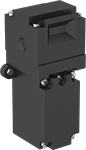
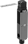
Access-Delay Frame-Mounted Safety Switches
|
Key Shown Actuating from the Side |
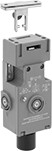 |  |
Style A | Style B |
 | |
Style C |
Housing | Conduit | ||||||||||||||||||
|---|---|---|---|---|---|---|---|---|---|---|---|---|---|---|---|---|---|---|---|
Style | No. of Circuits Controlled | Switch Starting Position | Switch Action | No. of Terminals | Switch Designation | Switching Current @ Voltage | Max. Voltage | Input Voltage | Holding Force, lbf | Ht. | Wd. | Dp. | Trade Size | Thread Type | Enclosure Rating | Each | |||
Screw-Terminal Wire Connection with Positive-Force Normally Closed Contacts | |||||||||||||||||||
| A | 3 | 1 Off and 2 On | Maintained | 6 | 3PST-1NO/2NC | 5 amp @ 120V AC, 2 amp @ 24V DC | 500V AC 250V DC | 24V AC, 24V DC | 225 | 4.7" | 2.3" | 1.4" | 1/2 | NPT | IP67, NEMA 6 | 7787K61 | 0000000 | ||
| A | 3 | 1 Off and 2 On | Maintained | 6 | 3PST-1NO/2NC | 5 amp @ 120V AC, 2 amp @ 24V DC | 500V AC 250V DC | 110V AC | 225 | 4.7" | 2.3" | 1.4" | 1/2 | NPT | IP67, NEMA 6 | 7787K62 | 000000 | ||
| B | 3 | 1 Off and 2 On | Maintained | 14 | 3PST-1NO/2NC | 3 amp @ 120V AC, 2.5 amp @ 24V DC | 240V AC 250V DC | 24V DC | 225 | 3.7" | 3.5" | 1.4" | 1/2 | NPT | IP67 | 7787K64 | 000000 | ||
Screw-Terminal Wire Connection with Positive-Force Normally Closed Contacts and Rotating Head | |||||||||||||||||||
| C | 4 | 2 Off and 2 On | Maintained | 8 | 4PST-2NO/2NC | 4 amp @ 120V AC, 4 amp @ 24V DC | 240V AC 24V DC | 24V AC, 24V DC | 225 | 7.6" | 1.2" | 1.6" | 1/2 | NPT | IP67 | 7787K12 | 000000 | ||
Abrasive Blaster Safety Switches
 |  |
Toggle Switch Actuator Shown in Use | Handle Actuator Shown in Use |
 | |
Trigger Actuator Shown in Use |
Electric
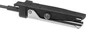 |  |
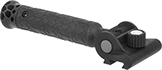
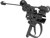
Handle Actuator | Trigger Actuator |
These switches send an electric signal to the control panel on the blaster to stop the spray. Because the signal is electric, these switches respond quickly even when your hose is long. They're recommended for hose that's over 100-ft. long and required by OSHA standards for hose that's over 200-ft. long.
Handle Actuator—Mount these below your hose to grip the switch and hose together. The large surface area provides leverage when squeezing the switch in your palm, even when wearing bulky gloves.
Trigger Actuator—Extra grip allows you to twist and maneuver the hose without straining your wrist. The trigger is simple to squeeze, even when wearing bulky gloves. To prevent accidents, an included secondary safety lock requires two motions to begin blasting.
Actuator Style | Switch Starting Position | No. of Terminals | Switch Designation | Switching Current @ Voltage | Max. Voltage, V DC | Handle Material | Housing Material | Electrical Connection Type | Wire Lead Lg., ft. | NEMA Type | Wd. | Lg. | Ht. | Features | Each | ||
|---|---|---|---|---|---|---|---|---|---|---|---|---|---|---|---|---|---|
| Handle | 1 Off | 3 | SPST-NC | 5 amp @ 24V DC | 28 | Stainless Steel | Plastic | Hardwire | 1 | — | 2 1/2" | 5" | 3" | — | 5053N14 | 0000000 | |
| Trigger | 1 Off and 1 On | 5 | SPST-NO | 15 amp @ 24V DC | 24 | Plastic | Plastic | Plug In | — | L5-15 | 1 3/4" | 8" | 8 1/2" | Hose Clamps, Secondary Safety Lock | 5053N17 | 000000 |
Easy-Hold Abrasive Blaster Safety Switches
 |
Shown in Use |
Reduce fatigue during long blasting sessions—these switches are built into a holder for your blaster hose. The holder has a brace that adjusts to shift most of the hose’s thrust away from your arms and grip, and repositions for comfort or different blasting angles. Switch easily between right- and left-hand use without having to take it apart. The housing has upper and lower rail mounts for optional accessories such as a side handle or flashlight (both sold separately). The mounts swivel around the clamp to keep accessories steady as the hose twists during blasting.
Also known as deadman switches, these switches stop blasting if you lose control. They automatically spring back to the off position to prevent injuries and reduce wasted material. To avoid accidental activation, a secondary safety lock requires an additional motion to begin blasting.
Electric
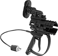 |
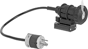
Trigger Actuator |
These switches send an electric signal to the control panel on the blaster to stop the spray. Because the signal is electric, these switches respond quickly even when your hose is long. They're recommended for hose that's over 100-ft. long and required by OSHA standards for hose that's over 200-ft. long.
Actuator Style | For Hose OD | Switch Starting Position | No. of Terminals | Switch Designation | Switching Current @ Voltage | Max. Voltage, V DC | Housing Material | Electrical Connection Type | NEMA Type | Wd. | Lg. | Ht. | Features | Each | ||
|---|---|---|---|---|---|---|---|---|---|---|---|---|---|---|---|---|
| Trigger | 1 3/16", 1 1/2", 1 7/8", 2 5/32" | 1 Off | 4 | SPST | 7 amp @ 12V DC 3 amp @ 24V DC | 24 | Plastic | Plug In | L5-15 | 5 1/4" | 11 3/4" | 13" | Adjustable Brace, Secondary Safety Lock, Upper and Lower Rail Mount | 8816N11 | 0000000 |