Filter by
Travel Length
Overall Length
Static Load Capacity
Height
Handle Type
Export Control Classification Number (ECCN)
DFARS Specialty Metals
Dovetail Milling-Machine Vises
 |
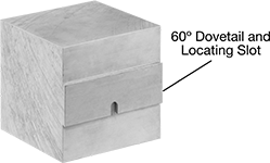
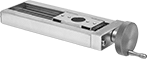
Designed to hold parts on 4- and 5-axis milling machines, these vises provide rigid clamping while exposing five full sides of the workpiece. This allows even complex parts to be completed in a single operation.
Vises require a dovetail and locating slot to be cut into the bottom side of your material. The dovetail-shaped jaws grip the matching dovetail in your material for consistent locating and high repeatability. Use a Carbide Dovetail End Mill to cut dovetail notches into your material.
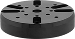
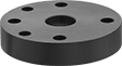
While the vises can be mounted directly to some machines or rotary tables, most will require an adapter plate.
With Dovetail Jaws
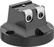 | 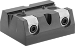 |
4.97" Dia. Vise | 5.95" Lg.×5" Wd. Vise |
For Max. Workpiece | Dovetail | |||||||||||||||
|---|---|---|---|---|---|---|---|---|---|---|---|---|---|---|---|---|
Lg. | Wd. | Ht. | Wt., lb. | Ht. | Angle | Dia. | Lg. | Wd. | Overall Ht. | Body Material | Clamp Material | Mounting Fasteners Included | Each | |||
Fixed Base | ||||||||||||||||
| 5 13/16" | 5 13/16" | 5 13/16" | 18 | 1/8" | 60° | 4.97" | — | — | 3" | Aluminum | Stainless Steel | Yes | 2549N2 | 0000000 | ||
| 6 3/4" | 6 3/4" | 6 3/4" | 30 | 1/8" | 60° | 4.97" | — | — | 3" | Aluminum | Stainless Steel | Yes | 2549N1 | 00000000 | ||
| 8" | 10" | 10" | 80 | 3/16" | 60° | — | 5.95" | 5" | 2 1/2" | Aluminum | Stainless Steel | Yes | 2549N3 | 00000000 | ||
 |
Dovetail | Slots | |||||||||||
|---|---|---|---|---|---|---|---|---|---|---|---|---|
Lg. | Wd. | Ht. | Ht. | Angle | No. of | Lg. | Wd. | Temp. Range, ° F | Each | |||
6061 Aluminum | ||||||||||||
3/4" Wide Dovetail | ||||||||||||
| 3 1/4" | 3 1/4" | 3 1/4" | 1/8" | 60° | 1 | 13/32" | 9/32" | -320 to 300 | 2610N13 | 0000000 | ||
| 5 13/16" | 5 13/16" | 5 13/16" | 1/8" | 60° | 1 | 13/32" | 9/32" | -320 to 300 | 2610N14 | 000000 | ||
1 1/2" Wide Dovetail | ||||||||||||
| 4" | 4" | 4" | 1/8" | 60° | 1 | 15/32" | 9/32" | -320 to 300 | 2610N11 | 000000 | ||
2 1/4" Wide Dovetail | ||||||||||||
| 7" | 7" | 5" | 3/16" | 60° | 2 | 11/16" | 5/16" | -320 to 300 | 2610N15 | 000000 | ||
| 8" | 10" | 10" | 3/16" | 60° | 2 | 11/16" | 5/16" | -320 to 300 | 2610N16 | 000000 | ||
Dovetail Blanks for Milling-Machine Vises
|
No need to prepare this material before machining parts in dovetail vises—the dovetails and locating slots are already cut in. The slots are sized to match the jaws on most dovetail milling-machine vises and ensure the workpiece is positioned accurately.
Dovetail | Slots | |||||||||||
|---|---|---|---|---|---|---|---|---|---|---|---|---|
Lg. | Wd. | Ht. | Ht. | Angle | No. of | Lg. | Wd. | Temp. Range, ° F | Each | |||
6061 Aluminum | ||||||||||||
3/4" Wide Dovetail | ||||||||||||
| 3 1/4" | 3 1/4" | 3 1/4" | 1/8" | 60° | 1 | 13/32" | 9/32" | -320 to 300 | 2610N13 | 0000000 | ||
| 5 13/16" | 5 13/16" | 5 13/16" | 1/8" | 60° | 1 | 13/32" | 9/32" | -320 to 300 | 2610N14 | 000000 | ||
1 1/2" Wide Dovetail | ||||||||||||
| 4" | 4" | 4" | 1/8" | 60° | 1 | 15/32" | 9/32" | -320 to 300 | 2610N11 | 000000 | ||
2 1/4" Wide Dovetail | ||||||||||||
| 7" | 7" | 5" | 3/16" | 60° | 2 | 11/16" | 5/16" | -320 to 300 | 2610N15 | 000000 | ||
| 8" | 10" | 10" | 3/16" | 60° | 2 | 11/16" | 5/16" | -320 to 300 | 2610N16 | 000000 | ||
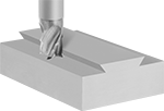
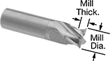
Carbide Dovetail End Mills for Dovetail Milling Vises
 |  |
Dovetail Cut Style |
Cut dovetail notches into your workpiece for use with our Dovetail Milling-Machine Vises. Made of solid carbide, these end mills are harder, stronger, and more wear resistant than high-speed steel and cobalt steel for the longest life and best finish on hard material. Their extreme hardness means they are brittle, so a highly rigid setup, such as a CNC machine, is necessary to prevent the end mill from breaking.
Mill | |||||||||||
|---|---|---|---|---|---|---|---|---|---|---|---|
Dia. | Dia. Tolerance | Thk. | Shank Dia. | Overall Lg. | Flute Spacing | For Use On | Cut Style | Each | |||
Titanium Carbon Nitride (TiCN)-Coated Carbide | |||||||||||
4 Flutes—60° Chamfer | |||||||||||
| 3/4" | -0.0010" to 0.0005" | 1/8" | 3/4" | 3" | Equal | Aluminum, Brass, Bronze, Hardened Steel, Iron, Nickel, Plastic, Stainless Steel, Steel, Titanium, Tool Steel | Dovetail | 2549N8 | 0000000 | ||
| 1 1/8" | -0.0005" to 0.0005" | 3/4" | 3/4" | 3 1/2" | Equal | Aluminum, Brass, Bronze, Hardened Steel, Iron, Nickel, Plastic, Stainless Steel, Steel, Titanium, Tool Steel | Dovetail | 2549N9 | 000000 | ||
Positioning Slides for Universal Robots
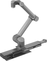 |  |
Shown with Robot Arm (Not Included) |
 |
Overall, mm | Carriage, mm | Load Cap., lb. | Robot Mount. Location | Floor Mount. Location | |||||||||||||
|---|---|---|---|---|---|---|---|---|---|---|---|---|---|---|---|---|---|
Lg. | Wd. | Ht. | Travel Lg., mm | Position Accuracy | Lg. | Wd. | Dynamic | Static | Mount. Hole Dia. (No. of Holes) | Mount. Fasteners Included | Mount. Hole Dia. (No. of Holes) | Mount. Fasteners Included | Includes | Each | |||
For UR3e, UR5e, UR10e, and UR16e Robot Arms | |||||||||||||||||
Aluminum | |||||||||||||||||
| 1,245 | 150 | 190 | 700 | ±0.1 mm | 170 | 200 | 2,450 | 2,700 | 6 mm, 8 mm (4) | Yes | 6 mm (10) | No | Slide Controller, Software Plug-In for Universal Robots | 3813N11 | 0000000000 | ||
| 1,550 | 150 | 190 | 1,000 | ±0.1 mm | 170 | 200 | 2,450 | 2,700 | 6 mm, 8 mm (4) | Yes | 6 mm (10) | No | Slide Controller, Software Plug-In for Universal Robots | 3813N12 | 000000000 | ||
| 1,855 | 150 | 190 | 1,300 | ±0.1 mm | 170 | 200 | 2,450 | 2,700 | 6 mm, 8 mm (4) | Yes | 6 mm (10) | No | Slide Controller, Software Plug-In for Universal Robots | 3813N13 | 000000000 | ||
| 2,160 | 150 | 190 | 1,600 | ±0.1 mm | 170 | 200 | 2,450 | 2,700 | 6 mm, 8 mm (4) | Yes | 6 mm (10) | No | Slide Controller, Software Plug-In for Universal Robots | 3813N14 | 000000000 | ||
| 2,337 | 150 | 190 | 1,800 | ±0.1 mm | 170 | 200 | 2,450 | 2,700 | 6 mm, 8 mm (4) | Yes | 6 mm (10) | No | Slide Controller, Software Plug-In for Universal Robots | 3813N15 | 000000000 | ||
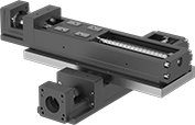
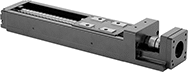
High-Load Positioning Slides
 |
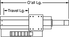
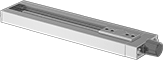
Made with Frelon bearings, these slides have over four times the load capacity of standard positioning slides. They have a precision lead screw for use in a variety of manual-positioning applications for laboratory and production equipment as well as for positioning parts for drilling, fastening, assembly, and measuring.
Note: Capacities listed are for horizontal mounting only.
Travel Distance per Turn—Travel distance per turn, also known as screw lead, is the distance the carriage moves with one revolution of the handle.
Mounting Plates—Two-axis mounting plates (sold separately) let you mount two slides together for motion along two axes.
Positioning Slides | Mounting Plates | ||||||||||||||||||||
|---|---|---|---|---|---|---|---|---|---|---|---|---|---|---|---|---|---|---|---|---|---|
Overall, mm | Carriage, mm | Handle | Carriage Mounting | Base Mounting | |||||||||||||||||
Travel Lg. | Travel Distance per Turn | Accuracy for Travel Distance per Turn | Ht., mm | Wd. | Lg. | Wd. | Lg. | Type | Dia., mm | Max. Temp., ° F | No. of Holes | Hole Thread Size | No. of Holes | For Fastener Thread Size | Mounting Fasteners Included | Each | Each | ||||
Aluminum Carriage and Base | |||||||||||||||||||||
490 lb. Static Load Capacity | |||||||||||||||||||||
| 4.35" | 0.05" | ±0.0006"/1" | 16 | 46 | 188.4 | 46 | 42 | Dial | 10.3 | 175 | 4 | M3 × 0.5 mm | 4 | M3 | No | 9222T11 | 000000000 | 9222T41 | 000000 | ||
| 10.35" | 0.05" | ±0.0006"/1" | 16 | 46 | 340.6 | 46 | 42 | Dial | 10.3 | 175 | 4 | M3 × 0.5 mm | 8 | M3 | No | 9222T12 | 000000 | 9222T41 | 00000 | ||
| 16.35" | 0.05" | ±0.0006"/1" | 16 | 46 | 489 | 46 | 42 | Dial | 10.3 | 175 | 4 | M3 × 0.5 mm | 12 | M3 | No | 9222T13 | 00000000 | 9222T41 | 00000 | ||
800 lb. Static Load Capacity | |||||||||||||||||||||
| 3.56" | 0.05" | ±0.0006"/1" | 25 | 46 | 187.9 | 46 | 62 | Dial | 18.3 | 175 | 4 | M4 × 0.7 mm | 3 | M5 | No | 9222T21 | 000000 | 9222T42 | 00000 | ||
| 9.56" | 0.05" | ±0.0006"/1" | 25 | 46 | 340.2 | 46 | 62 | Dial | 18.3 | 175 | 4 | M4 × 0.7 mm | 5 | M5 | No | 9222T22 | 000000 | 9222T42 | 00000 | ||
| 15.56" | 0.05" | ±0.0006"/1" | 25 | 46 | 492.6 | 46 | 62 | Dial | 18.3 | 175 | 4 | M4 × 0.7 mm | 8 | M5 | No | 9222T23 | 000000 | 9222T42 | 00000 | ||
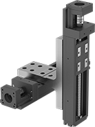
Dry-Running Positioning Slides for Stepper Motors
 |
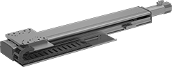
With PTFE sleeve bearings and a low-friction ball screw, these slides don’t require the mess and maintenance of lubrication but still give you precise positioning anywhere along the length of their stroke. Because they have sleeve bearings, they have fewer moving parts, so they perform better in dusty and wet environments than slides with ball bearings. They’re also better at handling impact and vibration.
All slides require a stepper motor, driver, and controller (not included) to operate. As part of this system, they move in precise increments, like the head on an inkjet printer. These positioning slides work well for automated assemblies and other applications that require fine, repeatable motion control.
Travel Distance per Turn—Travel distance per turn, also known as screw lead, is how far the carriage moves with one rotation of the ball screw.
Dynamic Load Cap. | For Max. Motor | Overall, mm | Carriage | |||||||||||||||||
|---|---|---|---|---|---|---|---|---|---|---|---|---|---|---|---|---|---|---|---|---|
Stroke Lg., mm | Horiz. | Vert. | Static Load Cap., lb. | Max. Speed, mm/s | Travel Distance per Turn, mm | Repeatability, mm | For Shaft Dia. | Speed, rpm | Torque, in·ozf | Lg. | Wd. | Ht. | Lg., mm | Wd., mm | Bearing Type | Base Material | Each | |||
For NEMA 17 Motor Frames | ||||||||||||||||||||
| 100 | Not Rated | Not Rated | 630 | 50 | 2 | -0.1 to 0.1 | 5 mm | 1,500 | 71 | 276 | 74 | 56 | 69 | 73 | Plain | Aluminum | 6650N11 | 0000000 | ||
| 200 | Not Rated | Not Rated | 630 | 50 | 2 | -0.1 to 0.1 | 5 mm | 1,500 | 71 | 376 | 74 | 56 | 69 | 73 | Plain | Aluminum | 6650N13 | 000000 | ||
| 300 | Not Rated | Not Rated | 630 | 50 | 2 | -0.1 to 0.1 | 5 mm | 1,500 | 71 | 476 | 74 | 56 | 69 | 73 | Plain | Aluminum | 6650N15 | 000000 | ||
| 400 | Not Rated | Not Rated | 630 | 50 | 2 | -0.1 to 0.1 | 5 mm | 1,500 | 71 | 576 | 74 | 56 | 69 | 73 | Plain | Aluminum | 6650N17 | 000000 | ||
| 500 | Not Rated | Not Rated | 630 | 50 | 2 | -0.1 to 0.1 | 5 mm | 1,500 | 71 | 676 | 74 | 56 | 69 | 73 | Plain | Aluminum | 6650N19 | 000000 | ||
| 600 | Not Rated | Not Rated | 630 | 50 | 2 | -0.1 to 0.1 | 5 mm | 1,500 | 71 | 776 | 74 | 56 | 69 | 73 | Plain | Aluminum | 6650N22 | 000000 | ||
For NEMA 23 Motor Frames | ||||||||||||||||||||
| 100 | Not Rated | Not Rated | 630 | 50 | 2 | -0.1 to 0.1 | 1/4" | 1,500 | 283 | 277 | 74 | 56 | 69 | 73 | Plain | Aluminum | 6650N12 | 000000 | ||
| 200 | Not Rated | Not Rated | 630 | 50 | 2 | -0.1 to 0.1 | 1/4" | 1,500 | 283 | 377 | 74 | 56 | 69 | 73 | Plain | Aluminum | 6650N14 | 000000 | ||
| 300 | Not Rated | Not Rated | 630 | 50 | 2 | -0.1 to 0.1 | 1/4" | 1,500 | 283 | 477 | 74 | 56 | 69 | 73 | Plain | Aluminum | 6650N16 | 000000 | ||
| 400 | Not Rated | Not Rated | 630 | 50 | 2 | -0.1 to 0.1 | 1/4" | 1,500 | 283 | 577 | 74 | 56 | 69 | 73 | Plain | Aluminum | 6650N18 | 000000 | ||
| 500 | Not Rated | Not Rated | 630 | 50 | 2 | -0.1 to 0.1 | 1/4" | 1,500 | 283 | 677 | 74 | 56 | 69 | 73 | Plain | Aluminum | 6650N21 | 000000 | ||
| 600 | Not Rated | Not Rated | 630 | 50 | 2 | -0.1 to 0.1 | 1/4" | 1,500 | 283 | 777 | 74 | 56 | 69 | 73 | Plain | Aluminum | 6650N23 | 000000 | ||
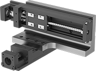
Precision Positioning Slides
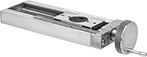 |  |
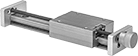
A linear scale and micrometer-like hand wheel measure travel distance in increments of 0.001". Rulon plain bearings allow these slides to move smoothly, even in dirty environments. Use them in a variety of manual-positioning applications for laboratory and production equipment as well as for positioning parts for drilling, fastening, assembly, and measuring.
Note: Capacities listed are for horizontal mounting. When mounted vertically, the load capacity is cut in half.
Travel Distance per Turn—Travel distance per turn, also known as screw lead, is the distance the carriage moves with one revolution of the handle.
Overall | Carriage | Handle | Carriage Mounting | Base Mounting | |||||||||||||||||
|---|---|---|---|---|---|---|---|---|---|---|---|---|---|---|---|---|---|---|---|---|---|
Travel Lg. | Travel Distance per Turn | Accuracy for Travel Distance per Turn | Ht. | Wd. | Lg. | Wd. | Lg. | Type | Dia. | Overhang | Linear Scale Graduations | Max. Temp., ° F | No. of Holes | Hole Thread Size | No. of Holes | For Fastener Thread Size | Mounting Fasteners Included | Each | |||
Aluminum Carriage and Base | |||||||||||||||||||||
15 lb. Static Load Capacity | |||||||||||||||||||||
| 1.5" | 0.05" | 0.00015"/1" | 0.61" | 1.5" | 5.6" | 0.62" | 1.5" | Hand Wheel | 1.75" | 0.59" | 0.025" | 180 | 4 | 6-32 | 2 | 8-32 | No | 5242A14 | 0000000 | ||
| 4.5" | 0.05" | 0.00015"/1" | 0.56" | 1.5" | 8.6" | 0.62" | 1.5" | Hand Wheel | 1.75" | 0.59" | 0.025" | 180 | 4 | 6-32 | 2 | 8-32 | No | 5242A11 | 000000 | ||
| 7.5" | 0.05" | 0.00015"/1" | 0.61" | 1.5" | 11.6" | 0.62" | 1.5" | Hand Wheel | 1.75" | 0.59" | 0.025" | 180 | 4 | 6-32 | 3 | 8-32 | No | 5242A12 | 000000 | ||
| 10.5" | 0.05" | 0.00015"/1" | 0.61" | 1.5" | 14.6" | 0.62" | 1.5" | Hand Wheel | 1.75" | 0.59" | 0.025" | 180 | 4 | 6-32 | 4 | 8-32 | No | 5242A13 | 000000 | ||
30 lb. Static Load Capacity | |||||||||||||||||||||
| 1.5" | 0.05" | 0.00015"/1" | 0.81" | 2.5" | 6.74" | 1.25" | 2.5" | Hand Wheel | 1.75" | 0.44" | 0.025" | 180 | 4 | 8-32 | 2 | 10-32 | No | 5242A19 | 000000 | ||
| 3.5" | 0.05" | 0.00015"/1" | 0.81" | 2.5" | 8.74" | 1.25" | 2.5" | Hand Wheel | 1.75" | 0.44" | 0.025" | 180 | 4 | 8-32 | 2 | 10-32 | No | 5242A21 | 000000 | ||
| 6.5" | 0.05" | 0.00015"/1" | 0.81" | 2.5" | 11.74" | 1.25" | 2.5" | Hand Wheel | 1.75" | 0.44" | 0.025" | 180 | 4 | 8-32 | 3 | 10-32 | No | 5242A22 | 000000 | ||
100 lb. Static Load Capacity | |||||||||||||||||||||
| 2" | 0.1" | 0.00015"/1" | 1.06" | 4" | 9.41" | 2.35" | 4" | Hand Wheel | 1.75" | 0.24" | 0.025" | 180 | 4 | 10-32 | 2 | 1/4"-20 | No | 5242A31 | 000000 | ||
| 5" | 0.1" | 0.00015"/1" | 1.06" | 4" | 12.41" | 2.35" | 4" | Hand Wheel | 1.75" | 0.24" | 0.025" | 180 | 4 | 10-32 | 3 | 1/4"-20 | No | 5242A32 | 00000000 | ||
| 8" | 0.1" | 0.00015"/1" | 1.06" | 4" | 15.41" | 2.35" | 4" | Hand Wheel | 1.75" | 0.24" | 0.025" | 180 | 4 | 10-32 | 4 | 1/4"-20 | No | 5242A33 | 00000000 | ||
| 11" | 0.1" | 0.00015"/1" | 1.06" | 4" | 18.41" | 2.35" | 4" | Hand Wheel | 1.75" | 0.24" | 0.025" | 180 | 4 | 10-32 | 5 | 1/4"-20 | No | 5242A34 | 00000000 | ||
| 14" | 0.1" | 0.00015"/1" | 1.06" | 4" | 21.41" | 2.35" | 4" | Hand Wheel | 1.75" | 0.24" | 0.025" | 180 | 4 | 10-32 | 6 | 1/4"-20 | No | 5242A35 | 00000000 | ||
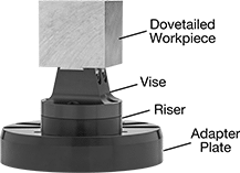
Positioning Slides
 |  |
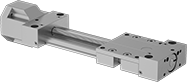
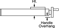
Dial Handle | Hand Wheel |
|
Use these slides in a variety of manual-positioning applications for laboratory and production equipment as well as for positioning parts for drilling, fastening, assembly, and measuring. Their Rulon plain bearings allow smooth movement in dirty environments.
Note: Capacities listed are for horizontal mounting. When mounted vertically, the load capacity is cut in half.
Travel Distance per Turn—Travel distance per turn, also known as screw lead, is the distance the carriage moves with one revolution of the handle.
Overall | Carriage | Handle | Carriage Mounting | Base Mounting | ||||||||||||||||
|---|---|---|---|---|---|---|---|---|---|---|---|---|---|---|---|---|---|---|---|---|
Travel Lg. | Travel Distance per Turn | Accuracy for Travel Distance per Turn | Ht. | Wd. | Lg. | Wd. | Lg. | Type | Dia. | Overhang | Max. Temp., ° F | No. of Holes | Hole Thread Size | No. of Holes | For Fastener Thread Size | Mounting Fasteners Included | Each | |||
Aluminum Carriage and Base | ||||||||||||||||||||
15 lb. Static Load Capacity | ||||||||||||||||||||
| 1.5" | 0.05" | 0.0007"/1" | 0.56" | 1.5" | 4.16" | 0.62" | 1.5" | Dial | 0.61" | — | 180 | 4 | 6-32 | 2 | 8-32 | No | 5236A15 | 0000000 | ||
| 4.5" | 0.05" | 0.0007"/1" | 0.56" | 1.5" | 7.16" | 0.62" | 1.5" | Dial | 0.61" | — | 180 | 4 | 6-32 | 2 | 8-32 | No | 5236A16 | 000000 | ||
| 7.5" | 0.05" | 0.0007"/1" | 0.56" | 1.5" | 10.16" | 0.62" | 1.5" | Dial | 0.61" | — | 180 | 4 | 6-32 | 3 | 8-32 | No | 5236A17 | 000000 | ||
| 10.5" | 0.05" | 0.0007"/1" | 0.56" | 1.5" | 13.16" | 0.62" | 1.5" | Dial | 0.61" | — | 180 | 4 | 6-32 | 4 | 8-32 | No | 5236A18 | 000000 | ||
30 lb. Static Load Capacity | ||||||||||||||||||||
| 1.5" | 0.05" | 0.0007"/1" | 0.81" | 2.5" | 6.72" | 1.25" | 2.5" | Hand Wheel | 1.75" | 0.44" | 180 | 4 | 8-32 | 2 | 10-32 | No | 5236A22 | 000000 | ||
| 3.5" | 0.05" | 0.0007"/1" | 0.81" | 2.5" | 8.72" | 1.25" | 2.5" | Hand Wheel | 1.75" | 0.44" | 180 | 4 | 8-32 | 2 | 10-32 | No | 5236A23 | 000000 | ||
| 6.5" | 0.05" | 0.0007"/1" | 0.81" | 2.5" | 11.72" | 1.25" | 2.5" | Hand Wheel | 1.75" | 0.44" | 180 | 4 | 8-32 | 3 | 10-32 | No | 5236A24 | 000000 | ||
| 9.5" | 0.05" | 0.0007"/1" | 0.81" | 2.5" | 14.72" | 1.25" | 2.5" | Hand Wheel | 1.75" | 0.44" | 180 | 4 | 8-32 | 4 | 10-32 | No | 5236A34 | 000000 | ||
| 12.5" | 0.05" | 0.0007"/1" | 0.81" | 2.5" | 17.72" | 1.25" | 2.5" | Hand Wheel | 1.75" | 0.44" | 180 | 4 | 8-32 | 5 | 10-32 | No | 5236A35 | 000000 | ||
100 lb. Static Load Capacity | ||||||||||||||||||||
| 2" | 0.1" | 0.0007"/1" | 1.06" | 4" | 8.73" | 2.35" | 4" | Hand Wheel | 1.75" | 0.24" | 180 | 4 | 10-32 | 2 | 1/4"-20 | No | 5236A27 | 000000 | ||
| 5" | 0.1" | 0.0007"/1" | 1.06" | 4" | 11.73" | 2.35" | 4" | Hand Wheel | 1.75" | 0.24" | 180 | 4 | 10-32 | 3 | 1/4"-20 | No | 5236A29 | 000000 | ||
| 8" | 0.1" | 0.0007"/1" | 1.06" | 4" | 14.73" | 2.35" | 4" | Hand Wheel | 1.75" | 0.24" | 180 | 4 | 10-32 | 4 | 1/4"-20 | No | 5236A31 | 000000 | ||
| 11" | 0.1" | 0.0007"/1" | 1.06" | 4" | 17.73" | 2.35" | 4" | Hand Wheel | 1.75" | 0.24" | 180 | 4 | 10-32 | 5 | 1/4"-20 | No | 5236A32 | 000000 | ||
| 14" | 0.1" | 0.0007"/1" | 1.06" | 4" | 20.73" | 2.35" | 4" | Hand Wheel | 1.75" | 0.24" | 180 | 4 | 10-32 | 6 | 1/4"-20 | No | 5236A33 | 000000 | ||
| 20" | 0.1" | 0.0007"/1" | 1.06" | 4" | 26.73" | 2.35" | 4" | Hand Wheel | 1.75" | 0.24" | 180 | 4 | 10-32 | 8 | 1/4"-20 | No | 5236A38 | 00000000 | ||
Positioning Slides for Stepper Motors
 |
Dynamic Load Cap., lb. | For Max. Motor | Overall, mm | Carriage | ||||||||||||||||
|---|---|---|---|---|---|---|---|---|---|---|---|---|---|---|---|---|---|---|---|
Stroke Lg., mm | Horiz. | Vert. | Max. Speed, mm/s | Travel Distance per Turn, mm | Repeatability, mm | For Shaft Dia. | Speed, rpm | Torque, in·ozf | Lg. | Wd. | Ht. | Lg., mm | Wd., mm | Bearing Type | Base Material | Each | |||
For NEMA 14 Motor Frames | |||||||||||||||||||
| 30 | 148 | 148 | 100 | 1 | -0.01 to 0.01 | 5 mm | 6,000 | 29.3 | 166 | 40 | 42 | 46 | 23 | Ball | Steel | 6734K211 | 0000000 | ||
| 80 | 148 | 148 | 100 | 1 | -0.01 to 0.01 | 5 mm | 6,000 | 29.3 | 216 | 40 | 42 | 46 | 23 | Ball | Steel | 6734K212 | 00000000 | ||
| 110 | 528 | 528 | 200 | 2 | -0.01 to 0.01 | 5 mm | 6,000 | 88.1 | 276 | 50 | 36 | 47.4 | 31 | Ball | Steel | 6734K214 | 00000000 | ||
| 130 | 148 | 148 | 100 | 1 | -0.01 to 0.01 | 5 mm | 6,000 | 29.3 | 266 | 40 | 42 | 46 | 23 | Ball | Steel | 6734K213 | 00000000 | ||
For NEMA 17 Motor Frames | |||||||||||||||||||
| 100 | 402 | 402 | 470 | 6 | -0.01 to 0.01 | 5 mm | 4,700 | 176 | 277 | 60 | 44.5 | 76 | 37.4 | Ball | Steel | 6734K811 | 00000000 | ||
| 110 | 528 | 528 | 200 | 2 | -0.01 to 0.01 | 5 mm | 6,000 | 88.1 | 276.5 | 50 | 42 | 47.4 | 31 | Ball | Steel | 6734K215 | 00000000 | ||
| 160 | 528 | 528 | 200 | 2 | -0.01 to 0.01 | 5 mm | 6,000 | 88.1 | 326.5 | 50 | 42 | 47.4 | 31 | Ball | Steel | 6734K216 | 00000000 | ||
| 200 | 402 | 402 | 470 | 6 | -0.01 to 0.01 | 5 mm | 4,700 | 176 | 377 | 60 | 44.5 | 76 | 37.4 | Ball | Steel | 6734K813 | 00000000 | ||
| 210 | 528 | 528 | 200 | 2 | -0.01 to 0.01 | 5 mm | 6,000 | 88.1 | 376.5 | 50 | 42 | 47.4 | 31 | Ball | Steel | 6734K217 | 00000000 | ||
For NEMA 23 Motor Frames | |||||||||||||||||||
| 100 | 402 | 402 | 470 | 6 | -0.01 to 0.01 | 1/4" | 4,700 | 176 | 280 | 60 | 56.4 | 76 | 37.4 | Ball | Steel | 6734K812 | 00000000 | ||
| 200 | 402 | 402 | 470 | 6 | -0.01 to 0.01 | 1/4" | 4,700 | 176 | 380 | 60 | 56.4 | 76 | 37.4 | Ball | Steel | 6734K814 | 00000000 | ||
| 300 | 395 | 395 | 790 | 10 | -0.01 to 0.01 | 1/4" | 6,000 | 176 | 480 | 60 | 56.4 | 76 | 37.4 | Ball | Steel | 6734K815 | 00000000 | ||
| 400 | 395 | 395 | 790 | 10 | -0.01 to 0.01 | 1/4" | 5,880 | 176 | 580 | 60 | 56.4 | 76 | 37.4 | Ball | Steel | 6734K816 | 00000000 | ||
| 500 | 395 | 395 | 650 | 10 | -0.01 to 0.01 | 1/4" | 3,900 | 176 | 680 | 60 | 56.4 | 76 | 37.4 | Ball | Steel | 6734K817 | 00000000 | ||
| 600 | 395 | 395 | 470 | 10 | -0.01 to 0.01 | 1/4" | 2,820 | 176 | 780 | 60 | 56.4 | 76 | 37.4 | Ball | Steel | 6734K818 | 00000000 | ||