


Filter by
System of Measurement
Length
Thread Size


Shaft Diameter
End Type
Specifications Met
Minimum Hardness
Mount Type


Tolerance Rating
DFARS Specialty Metals
Export Control Classification Number (ECCN)
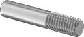
Pull-Out Dowel Pins
Steel
Spring Steel—These pins won't deform from stress and vibration. They're stronger than stainless steel but not quite as strong as alloy steel. Pins perform best in dry environments since moisture will cause them to rust.
Each | |||||||||||||||||||||||||||||||||||||||||||||||||||||||||||||||||||||||||||||||||||||||||||||||||||
|---|---|---|---|---|---|---|---|---|---|---|---|---|---|---|---|---|---|---|---|---|---|---|---|---|---|---|---|---|---|---|---|---|---|---|---|---|---|---|---|---|---|---|---|---|---|---|---|---|---|---|---|---|---|---|---|---|---|---|---|---|---|---|---|---|---|---|---|---|---|---|---|---|---|---|---|---|---|---|---|---|---|---|---|---|---|---|---|---|---|---|---|---|---|---|---|---|---|---|---|
Lg., mm | Dia. Tolerance, mm | Thread Size | Double Shear Breaking Strength, lbf | Min. Hardness | Specs. Met | 1-49 | 50-199 | 200-Up | |||||||||||||||||||||||||||||||||||||||||||||||||||||||||||||||||||||||||||||||||||||||||||
Spring Steel | |||||||||||||||||||||||||||||||||||||||||||||||||||||||||||||||||||||||||||||||||||||||||||||||||||
10 mm Diameter | |||||||||||||||||||||||||||||||||||||||||||||||||||||||||||||||||||||||||||||||||||||||||||||||||||
| 24 | 0.006 to 0.015 | M6 × 1 mm | Not Rated | Rockwell C52 | DIN 7979D-m6 | 97355A492 | 00000 | 00000 | 00000 | ||||||||||||||||||||||||||||||||||||||||||||||||||||||||||||||||||||||||||||||||||||||||||
| 28 | 0.006 to 0.015 | M6 × 1 mm | Not Rated | Rockwell C52 | DIN 7979D-m6 | 97355A496 | 0000 | 0000 | 0000 | ||||||||||||||||||||||||||||||||||||||||||||||||||||||||||||||||||||||||||||||||||||||||||
| 30 | 0.006 to 0.015 | M6 × 1 mm | Not Rated | Rockwell C52 | DIN 7979D-m6 | 97355A500 | 0000 | 0000 | 0000 | ||||||||||||||||||||||||||||||||||||||||||||||||||||||||||||||||||||||||||||||||||||||||||
| 32 | 0.006 to 0.015 | M6 × 1 mm | Not Rated | Rockwell C52 | DIN 7979D-m6 | 97355A504 | 0000 | 0000 | 0000 | ||||||||||||||||||||||||||||||||||||||||||||||||||||||||||||||||||||||||||||||||||||||||||
| 36 | 0.006 to 0.015 | M6 × 1 mm | Not Rated | Rockwell C52 | DIN 7979D-m6 | 97355A505 | 0000 | 0000 | 0000 | ||||||||||||||||||||||||||||||||||||||||||||||||||||||||||||||||||||||||||||||||||||||||||
| 40 | 0.006 to 0.015 | M6 × 1 mm | Not Rated | Rockwell C52 | DIN 7979D-m6 | 97355A506 | 0000 | 0000 | 0000 | ||||||||||||||||||||||||||||||||||||||||||||||||||||||||||||||||||||||||||||||||||||||||||
| 50 | 0.006 to 0.015 | M6 × 1 mm | Not Rated | Rockwell C52 | DIN 7979D-m6 | 97355A507 | 0000 | 0000 | 0000 | ||||||||||||||||||||||||||||||||||||||||||||||||||||||||||||||||||||||||||||||||||||||||||
| 60 | 0.006 to 0.015 | M6 × 1 mm | Not Rated | Rockwell C52 | DIN 7979D-m6 | 97355A515 | 0000 | 0000 | 0000 | ||||||||||||||||||||||||||||||||||||||||||||||||||||||||||||||||||||||||||||||||||||||||||
| 70 | 0.006 to 0.015 | M6 × 1 mm | Not Rated | Rockwell C52 | DIN 7979D-m6 | 97355A518 | 0000 | 0000 | 0000 | ||||||||||||||||||||||||||||||||||||||||||||||||||||||||||||||||||||||||||||||||||||||||||
| 80 | 0.006 to 0.015 | M6 × 1 mm | Not Rated | Rockwell C52 | DIN 7979D-m6 | 97355A520 | 0000 | 0000 | 0000 | ||||||||||||||||||||||||||||||||||||||||||||||||||||||||||||||||||||||||||||||||||||||||||
12 mm Diameter | |||||||||||||||||||||||||||||||||||||||||||||||||||||||||||||||||||||||||||||||||||||||||||||||||||
| 24 | 0.007 to 0.018 | M6 × 1 mm | 24,000 | Rockwell C52 | DIN 7979D-m6 | 97355A531 | 0000 | 0000 | 0000 | ||||||||||||||||||||||||||||||||||||||||||||||||||||||||||||||||||||||||||||||||||||||||||
| 30 | 0.007 to 0.018 | M6 × 1 mm | 24,000 | Rockwell C52 | DIN 7979D-m6 | 97355A535 | 0000 | 0000 | 0000 | ||||||||||||||||||||||||||||||||||||||||||||||||||||||||||||||||||||||||||||||||||||||||||
| 36 | 0.007 to 0.018 | M6 × 1 mm | 24,000 | Rockwell C52 | DIN 7979D-m6 | 97355A539 | 0000 | 0000 | 0000 | ||||||||||||||||||||||||||||||||||||||||||||||||||||||||||||||||||||||||||||||||||||||||||
| 45 | 0.007 to 0.018 | M6 × 1 mm | 24,000 | Rockwell C52 | DIN 7979D-m6 | 97355A543 | 0000 | 0000 | 0000 | ||||||||||||||||||||||||||||||||||||||||||||||||||||||||||||||||||||||||||||||||||||||||||
| 50 | 0.007 to 0.018 | M6 × 1 mm | 24,000 | Rockwell C52 | DIN 7979D-m6 | 97355A547 | 0000 | 0000 | 0000 | ||||||||||||||||||||||||||||||||||||||||||||||||||||||||||||||||||||||||||||||||||||||||||
| 60 | 0.007 to 0.018 | M6 × 1 mm | 24,000 | Rockwell C52 | DIN 7979D-m6 | 97355A551 | 0000 | 0000 | 0000 | ||||||||||||||||||||||||||||||||||||||||||||||||||||||||||||||||||||||||||||||||||||||||||
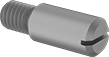
Single-End Studs
 |
Screw the threaded end of these studs into a tapped hole, and use the unthreaded end as a pivot point, hinge, shaft, or locator pin.
Steel—These studs are steel for strength and wear resistance. They’re best for dry environments since moisture will cause them to rust. All meet ISO 2342 (formerly DIN 427), an international standard for fastener dimensions.
Shaft, mm | |||||||||||||||||||||||||||||||||||||||||||||||||||||||||||||||||||||||||||||||||||||||||||||||||||
|---|---|---|---|---|---|---|---|---|---|---|---|---|---|---|---|---|---|---|---|---|---|---|---|---|---|---|---|---|---|---|---|---|---|---|---|---|---|---|---|---|---|---|---|---|---|---|---|---|---|---|---|---|---|---|---|---|---|---|---|---|---|---|---|---|---|---|---|---|---|---|---|---|---|---|---|---|---|---|---|---|---|---|---|---|---|---|---|---|---|---|---|---|---|---|---|---|---|---|---|
Lg., mm | Thread Lg., mm | Lg. | Dia. | Dia. Tolerance | Tensile Strength | Hardness | Drive Style | Specs. Met | Pkg. Qty. | Pkg. | |||||||||||||||||||||||||||||||||||||||||||||||||||||||||||||||||||||||||||||||||||||||||
Steel | |||||||||||||||||||||||||||||||||||||||||||||||||||||||||||||||||||||||||||||||||||||||||||||||||||
M6 × 1 mm | |||||||||||||||||||||||||||||||||||||||||||||||||||||||||||||||||||||||||||||||||||||||||||||||||||
| 10 | 7.2 | 2.8 | 6 | -0.18 to 0 | Not Rated | Rockwell B75 | Slotted | DIN 427, ISO 2342 | 10 | 97493A158 | 000000 | ||||||||||||||||||||||||||||||||||||||||||||||||||||||||||||||||||||||||||||||||||||||||
| 12 | 7.2 | 4.8 | 6 | -0.18 to 0 | Not Rated | Rockwell B75 | Slotted | DIN 427, ISO 2342 | 10 | 97493A159 | 00000 | ||||||||||||||||||||||||||||||||||||||||||||||||||||||||||||||||||||||||||||||||||||||||
| 16 | 7.2 | 8.8 | 6 | -0.18 to 0 | Not Rated | Rockwell B75 | Slotted | DIN 427, ISO 2342 | 10 | 97493A125 | 0000 | ||||||||||||||||||||||||||||||||||||||||||||||||||||||||||||||||||||||||||||||||||||||||
| 18 | 7.2 | 10.8 | 6 | -0.18 to 0 | Not Rated | Rockwell B75 | Slotted | DIN 427, ISO 2342 | 10 | 97493A161 | 00000 | ||||||||||||||||||||||||||||||||||||||||||||||||||||||||||||||||||||||||||||||||||||||||
| 20 | 7.2 | 12.8 | 6 | -0.18 to 0 | Not Rated | Rockwell B75 | Slotted | DIN 427, ISO 2342 | 10 | 97493A162 | 00000 | ||||||||||||||||||||||||||||||||||||||||||||||||||||||||||||||||||||||||||||||||||||||||
| 25 | 7.2 | 17.8 | 6 | -0.18 to 0 | Not Rated | Rockwell B75 | Slotted | DIN 427, ISO 2342 | 5 | 97493A163 | 0000 | ||||||||||||||||||||||||||||||||||||||||||||||||||||||||||||||||||||||||||||||||||||||||
| 30 | 7.2 | 22.8 | 6 | -0.18 to 0 | Not Rated | Rockwell B75 | Slotted | DIN 427, ISO 2342 | 10 | 97493A126 | 00000 | ||||||||||||||||||||||||||||||||||||||||||||||||||||||||||||||||||||||||||||||||||||||||
Vented Pull-Out Dowel Pins
Flat Shaft
Lg., mm | Dia. Tolerance, mm | Thread Size | Double Shear Breaking Strength, lbf | Min. Hardness | Specs. Met | Each | |||||||||||||||||||||||||||||||||||||||||||||||||||||||||||||||||||||||||||||||||||||||||||||
|---|---|---|---|---|---|---|---|---|---|---|---|---|---|---|---|---|---|---|---|---|---|---|---|---|---|---|---|---|---|---|---|---|---|---|---|---|---|---|---|---|---|---|---|---|---|---|---|---|---|---|---|---|---|---|---|---|---|---|---|---|---|---|---|---|---|---|---|---|---|---|---|---|---|---|---|---|---|---|---|---|---|---|---|---|---|---|---|---|---|---|---|---|---|---|---|---|---|---|---|
Spring Steel | |||||||||||||||||||||||||||||||||||||||||||||||||||||||||||||||||||||||||||||||||||||||||||||||||||
10 mm Diameter | |||||||||||||||||||||||||||||||||||||||||||||||||||||||||||||||||||||||||||||||||||||||||||||||||||
| 24 | 0.006 to 0.015 | M6 × 1 mm | Not Rated | Rockwell C52 | DIN 7979D-m6 | 98432A303 | 00000 | ||||||||||||||||||||||||||||||||||||||||||||||||||||||||||||||||||||||||||||||||||||||||||||
| 28 | 0.006 to 0.015 | M6 × 1 mm | Not Rated | Rockwell C52 | DIN 7979D-m6 | 98432A307 | 0000 | ||||||||||||||||||||||||||||||||||||||||||||||||||||||||||||||||||||||||||||||||||||||||||||
| 30 | 0.006 to 0.015 | M6 × 1 mm | Not Rated | Rockwell C52 | DIN 7979D-m6 | 98432A311 | 0000 | ||||||||||||||||||||||||||||||||||||||||||||||||||||||||||||||||||||||||||||||||||||||||||||
| 36 | 0.006 to 0.015 | M6 × 1 mm | Not Rated | Rockwell C52 | DIN 7979D-m6 | 98432A315 | 0000 | ||||||||||||||||||||||||||||||||||||||||||||||||||||||||||||||||||||||||||||||||||||||||||||
| 40 | 0.006 to 0.015 | M6 × 1 mm | Not Rated | Rockwell C52 | DIN 7979D-m6 | 98432A319 | 0000 | ||||||||||||||||||||||||||||||||||||||||||||||||||||||||||||||||||||||||||||||||||||||||||||
| 50 | 0.006 to 0.015 | M6 × 1 mm | Not Rated | Rockwell C52 | DIN 7979D-m6 | 98432A323 | 0000 | ||||||||||||||||||||||||||||||||||||||||||||||||||||||||||||||||||||||||||||||||||||||||||||
| 60 | 0.006 to 0.015 | M6 × 1 mm | Not Rated | Rockwell C52 | DIN 7979D-m6 | 98432A327 | 0000 | ||||||||||||||||||||||||||||||||||||||||||||||||||||||||||||||||||||||||||||||||||||||||||||
| 70 | 0.006 to 0.015 | M6 × 1 mm | Not Rated | Rockwell C52 | DIN 7979D-m6 | 98432A332 | 0000 | ||||||||||||||||||||||||||||||||||||||||||||||||||||||||||||||||||||||||||||||||||||||||||||
12 mm Diameter | |||||||||||||||||||||||||||||||||||||||||||||||||||||||||||||||||||||||||||||||||||||||||||||||||||
| 24 | 0.007 to 0.018 | M6 × 1 mm | 24,000 | Rockwell C52 | DIN 7979D-m6 | 98432A341 | 0000 | ||||||||||||||||||||||||||||||||||||||||||||||||||||||||||||||||||||||||||||||||||||||||||||
| 30 | 0.007 to 0.018 | M6 × 1 mm | 24,000 | Rockwell C52 | DIN 7979D-m6 | 98432A345 | 0000 | ||||||||||||||||||||||||||||||||||||||||||||||||||||||||||||||||||||||||||||||||||||||||||||
| 36 | 0.007 to 0.018 | M6 × 1 mm | 24,000 | Rockwell C52 | DIN 7979D-m6 | 98432A349 | 0000 | ||||||||||||||||||||||||||||||||||||||||||||||||||||||||||||||||||||||||||||||||||||||||||||
| 40 | 0.007 to 0.018 | M6 × 1 mm | 24,000 | Rockwell C52 | DIN 7979D-m6 | 98432A353 | 0000 | ||||||||||||||||||||||||||||||||||||||||||||||||||||||||||||||||||||||||||||||||||||||||||||
| 45 | 0.007 to 0.018 | M6 × 1 mm | 24,000 | Rockwell C52 | DIN 7979D-m6 | 98432A357 | 0000 | ||||||||||||||||||||||||||||||||||||||||||||||||||||||||||||||||||||||||||||||||||||||||||||
| 50 | 0.007 to 0.018 | M6 × 1 mm | 24,000 | Rockwell C52 | DIN 7979D-m6 | 98432A362 | 0000 | ||||||||||||||||||||||||||||||||||||||||||||||||||||||||||||||||||||||||||||||||||||||||||||
| 60 | 0.007 to 0.018 | M6 × 1 mm | 24,000 | Rockwell C52 | DIN 7979D-m6 | 98432A366 | 0000 | ||||||||||||||||||||||||||||||||||||||||||||||||||||||||||||||||||||||||||||||||||||||||||||
18-8 Stainless Steel | |||||||||||||||||||||||||||||||||||||||||||||||||||||||||||||||||||||||||||||||||||||||||||||||||||
10 mm Diameter | |||||||||||||||||||||||||||||||||||||||||||||||||||||||||||||||||||||||||||||||||||||||||||||||||||
| 20 | 0.006 to 0.015 | M6 × 1 mm | 101,000 | Rockwell C18 | DIN 7979C-m6 | 98432A133 | 00000 | ||||||||||||||||||||||||||||||||||||||||||||||||||||||||||||||||||||||||||||||||||||||||||||
| 40 | 0.006 to 0.015 | M6 × 1 mm | 101,000 | Rockwell C18 | DIN 7979C-m6 | 98432A137 | 00000 | ||||||||||||||||||||||||||||||||||||||||||||||||||||||||||||||||||||||||||||||||||||||||||||
| 60 | 0.006 to 0.015 | M6 × 1 mm | 101,000 | Rockwell C18 | DIN 7979C-m6 | 98432A139 | 00000 | ||||||||||||||||||||||||||||||||||||||||||||||||||||||||||||||||||||||||||||||||||||||||||||
| 80 | 0.006 to 0.015 | M6 × 1 mm | 101,000 | Rockwell C18 | DIN 7979C-m6 | 98432A141 | 00000 | ||||||||||||||||||||||||||||||||||||||||||||||||||||||||||||||||||||||||||||||||||||||||||||
12 mm Diameter | |||||||||||||||||||||||||||||||||||||||||||||||||||||||||||||||||||||||||||||||||||||||||||||||||||
| 24 | 0.007 to 0.018 | M6 × 1 mm | 101,000 | Rockwell C18 | DIN 7979C-m6 | 98432A142 | 00000 | ||||||||||||||||||||||||||||||||||||||||||||||||||||||||||||||||||||||||||||||||||||||||||||
| 40 | 0.007 to 0.018 | M6 × 1 mm | 101,000 | Rockwell C18 | DIN 7979C-m6 | 98432A145 | 00000 | ||||||||||||||||||||||||||||||||||||||||||||||||||||||||||||||||||||||||||||||||||||||||||||
| 50 | 0.007 to 0.018 | M6 × 1 mm | 101,000 | Rockwell C18 | DIN 7979C-m6 | 98432A146 | 00000 | ||||||||||||||||||||||||||||||||||||||||||||||||||||||||||||||||||||||||||||||||||||||||||||
| 80 | 0.007 to 0.018 | M6 × 1 mm | 101,000 | Rockwell C18 | DIN 7979C-m6 | 98432A148 | 00000 | ||||||||||||||||||||||||||||||||||||||||||||||||||||||||||||||||||||||||||||||||||||||||||||
Steel Headless Slotted Precision Shoulder Screws
Threaded Taper Pins
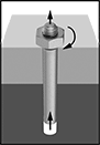 |
Tighten the nut to draw the pin out of the hole. |
Threads on these pins stick out for easy removal from blind holes. Tighten the hex nut to draw the pin out. Often used for positioning components and securing assemblies, they taper at a uniform rate to fit in tapered holes. For a snug fit, use a tapered drill bit that matches the pin number for inch sizes or the small end diameter for metric sizes. They have slightly rounded edges to aid insertion.
Metric
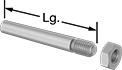 |
Length for metric pins measures the overall length, including the thread.
12L14 Carbon Steel—12L14 Carbon steel pins have good strength.
Breaking Strength—Breaking strength is measured as single shear, which is the force required to break the pin into two pieces.
Lg., mm | Large End Dia., mm | Rate of Taper | Thread Lg., mm | Thread Size | Min. Hardness | Breaking Strength, psi | Specs. Met | Pkg. Qty. | Pkg. | ||||||||||||||||||||||||||||||||||||||||||||||||||||||||||||||||||||||||||||||||||||||||||
|---|---|---|---|---|---|---|---|---|---|---|---|---|---|---|---|---|---|---|---|---|---|---|---|---|---|---|---|---|---|---|---|---|---|---|---|---|---|---|---|---|---|---|---|---|---|---|---|---|---|---|---|---|---|---|---|---|---|---|---|---|---|---|---|---|---|---|---|---|---|---|---|---|---|---|---|---|---|---|---|---|---|---|---|---|---|---|---|---|---|---|---|---|---|---|---|---|---|---|---|
12L14 Carbon Steel | |||||||||||||||||||||||||||||||||||||||||||||||||||||||||||||||||||||||||||||||||||||||||||||||||||
6 mm Small End Diameter | |||||||||||||||||||||||||||||||||||||||||||||||||||||||||||||||||||||||||||||||||||||||||||||||||||
| 45 | 6.5 | 1:50 | 19 | M6 | Rockwell B80 | 34,500 | DIN 7977, ISO 8737 | 5 | 92281A714 | 00000 | |||||||||||||||||||||||||||||||||||||||||||||||||||||||||||||||||||||||||||||||||||||||||
| 50 | 6.6 | 1:50 | 19 | M6 | Rockwell B80 | 34,500 | DIN 7977, ISO 8737 | 5 | 92281A715 | 0000 | |||||||||||||||||||||||||||||||||||||||||||||||||||||||||||||||||||||||||||||||||||||||||
| 55 | 6.7 | 1:50 | 19 | M6 | Rockwell B80 | 34,500 | DIN 7977, ISO 8737 | 5 | 92281A716 | 00000 | |||||||||||||||||||||||||||||||||||||||||||||||||||||||||||||||||||||||||||||||||||||||||
| 60 | 6.8 | 1:50 | 19 | M6 | Rockwell B80 | 34,500 | DIN 7977, ISO 8737 | 5 | 92281A717 | 00000 | |||||||||||||||||||||||||||||||||||||||||||||||||||||||||||||||||||||||||||||||||||||||||
303 Stainless Steel | |||||||||||||||||||||||||||||||||||||||||||||||||||||||||||||||||||||||||||||||||||||||||||||||||||
6 mm Small End Diameter | |||||||||||||||||||||||||||||||||||||||||||||||||||||||||||||||||||||||||||||||||||||||||||||||||||
| 45 | 6.5 | 1:50 | 19 | M6 | Rockwell B96 | 34,500 | DIN 7977, ISO 8737 | 5 | 92284A714 | 00000 | |||||||||||||||||||||||||||||||||||||||||||||||||||||||||||||||||||||||||||||||||||||||||
| 50 | 6.6 | 1:50 | 19 | M6 | Rockwell B96 | 34,500 | DIN 7977, ISO 8737 | 5 | 92284A715 | 00000 | |||||||||||||||||||||||||||||||||||||||||||||||||||||||||||||||||||||||||||||||||||||||||
| 55 | 6.7 | 1:50 | 19 | M6 | Rockwell B96 | 34,500 | DIN 7977, ISO 8737 | 5 | 92284A716 | 00000 | |||||||||||||||||||||||||||||||||||||||||||||||||||||||||||||||||||||||||||||||||||||||||
| 60 | 6.8 | 1:50 | 19 | M6 | Rockwell B96 | 34,500 | DIN 7977, ISO 8737 | 5 | 92284A717 | 00000 | |||||||||||||||||||||||||||||||||||||||||||||||||||||||||||||||||||||||||||||||||||||||||
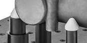
Fixturing for Parts Inspection
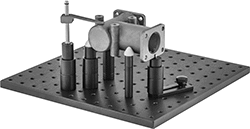 |
From towers and brackets to standoffs and supports, these components are the building blocks for your custom fixturing setup. They elevate parts so you can access a variety of angles for measuring and inspecting while protecting your measuring device from hitting the inspection table. You’ll often see them used with coordinate measuring machines (CMMs). They’re not for use in machining applications.
Kits
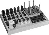 |
No. of Pieces | Includes | Each | |||||||||||||||||||||||||||||||||||||||||||||||||||||||||||||||||||||||||||||||||||||||||||||||||
|---|---|---|---|---|---|---|---|---|---|---|---|---|---|---|---|---|---|---|---|---|---|---|---|---|---|---|---|---|---|---|---|---|---|---|---|---|---|---|---|---|---|---|---|---|---|---|---|---|---|---|---|---|---|---|---|---|---|---|---|---|---|---|---|---|---|---|---|---|---|---|---|---|---|---|---|---|---|---|---|---|---|---|---|---|---|---|---|---|---|---|---|---|---|---|---|---|---|---|---|
M6 Threads | |||||||||||||||||||||||||||||||||||||||||||||||||||||||||||||||||||||||||||||||||||||||||||||||||||
| 42 | 2 Hold-Down Clamps—38 mm Reach × 38 mm O'all Ht. 4 Hold-Down Clamps—58 mm Reach × 75 mm O'all Ht. 3 Standoffs—13 mm Dia. × 20 mm Ht. 3 Standoffs—13 mm Dia. × 25 mm Ht. 3 Standoffs—13 mm Dia. × 50 mm Ht. 3 Standoffs—19 mm Dia. × 20 mm Ht. 3 Standoffs—19 mm Dia. × 25 mm Ht. 3 Standoffs—19 mm Dia. × 50 mm Ht. 3 Standoffs—25 mm Dia. × 20 mm Ht. 3 Standoffs—25 mm Dia. × 25 mm Ht. 3 Standoffs—25 mm Dia. × 50 mm Ht. 1 Adjustable-Height Standoff—13 mm Dia. 2 Pin Supports—13 mm Dia. × 25 mm Ht. 3 Cone Supports 1 Positioning Plate—35 mm Lg. 1 Positioning Plate—76 mm Lg. 1 Acetal Plastic Tray | 1409N51 | 0000000 | ||||||||||||||||||||||||||||||||||||||||||||||||||||||||||||||||||||||||||||||||||||||||||||||||
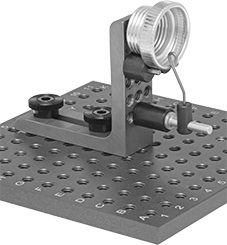
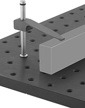
Fixture Towers
 | 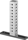 |
Fixture towers give you four vertical grids and a small horizontal one on top, so you can set up custom scaffolds to position parts in several planes. Their height makes them useful for propping up large workpieces. Each tower can uphold multiple parts. The threaded holes on the vertical grids are labeled with letters and numbers, making it easy to identify holes.
Tower, mm | Base, mm | ||||||||||||||||||||||||||||||||||||||||||||||||||||||||||||||||||||||||||||||||||||||||||||||||||
|---|---|---|---|---|---|---|---|---|---|---|---|---|---|---|---|---|---|---|---|---|---|---|---|---|---|---|---|---|---|---|---|---|---|---|---|---|---|---|---|---|---|---|---|---|---|---|---|---|---|---|---|---|---|---|---|---|---|---|---|---|---|---|---|---|---|---|---|---|---|---|---|---|---|---|---|---|---|---|---|---|---|---|---|---|---|---|---|---|---|---|---|---|---|---|---|---|---|---|---|
Overall Ht., mm | Lg. | Wd. | Lg. | Wd. | Number of Holes | Material | Includes | Each | |||||||||||||||||||||||||||||||||||||||||||||||||||||||||||||||||||||||||||||||||||||||||||
M6 Hole Thread Size | |||||||||||||||||||||||||||||||||||||||||||||||||||||||||||||||||||||||||||||||||||||||||||||||||||
| 150 | 25 | 25 | 127 | 25 | 33 | Aluminum | Two M6 Knurled Knobs | 1409N73 | 0000000 | ||||||||||||||||||||||||||||||||||||||||||||||||||||||||||||||||||||||||||||||||||||||||||
Angle Brackets
 | 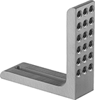 |
Slots, mm | |||||||||||||||||||||||||||||||||||||||||||||||||||||||||||||||||||||||||||||||||||||||||||||||||||
|---|---|---|---|---|---|---|---|---|---|---|---|---|---|---|---|---|---|---|---|---|---|---|---|---|---|---|---|---|---|---|---|---|---|---|---|---|---|---|---|---|---|---|---|---|---|---|---|---|---|---|---|---|---|---|---|---|---|---|---|---|---|---|---|---|---|---|---|---|---|---|---|---|---|---|---|---|---|---|---|---|---|---|---|---|---|---|---|---|---|---|---|---|---|---|---|---|---|---|---|
Lg., mm | Wd., mm | Ht., mm | Lg. | Wd. | Number of Holes | Material | Includes | Each | |||||||||||||||||||||||||||||||||||||||||||||||||||||||||||||||||||||||||||||||||||||||||||
M6 Hole Thread Size | |||||||||||||||||||||||||||||||||||||||||||||||||||||||||||||||||||||||||||||||||||||||||||||||||||
| 76 | 25 | 76 | 44 | 7.8 | 18 | Aluminum | Two M6 Bolts | 1409N68 | 000000 | ||||||||||||||||||||||||||||||||||||||||||||||||||||||||||||||||||||||||||||||||||||||||||
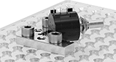
Magnetic Supports
 | |
Dia., mm | Ht., mm | Thread Lg., mm | Max. Magnetic Pull, lbf | Material | Each | ||||||||||||||||||||||||||||||||||||||||||||||||||||||||||||||||||||||||||||||||||||||||||||||
|---|---|---|---|---|---|---|---|---|---|---|---|---|---|---|---|---|---|---|---|---|---|---|---|---|---|---|---|---|---|---|---|---|---|---|---|---|---|---|---|---|---|---|---|---|---|---|---|---|---|---|---|---|---|---|---|---|---|---|---|---|---|---|---|---|---|---|---|---|---|---|---|---|---|---|---|---|---|---|---|---|---|---|---|---|---|---|---|---|---|---|---|---|---|---|---|---|---|---|---|
M6 × 1 mm Threads | |||||||||||||||||||||||||||||||||||||||||||||||||||||||||||||||||||||||||||||||||||||||||||||||||||
| 13 | 25 | 6.2 | 9 | Steel | 1409N61 | 000000 | |||||||||||||||||||||||||||||||||||||||||||||||||||||||||||||||||||||||||||||||||||||||||||||
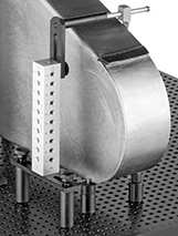
Magnetic V-Supports
 |  |
Dia., mm | Ht., mm | V Wd., mm | V Dp., mm | V Angle | Thread Lg., mm | Max. Magnetic Pull, lbf | Material | Each | |||||||||||||||||||||||||||||||||||||||||||||||||||||||||||||||||||||||||||||||||||||||||||
|---|---|---|---|---|---|---|---|---|---|---|---|---|---|---|---|---|---|---|---|---|---|---|---|---|---|---|---|---|---|---|---|---|---|---|---|---|---|---|---|---|---|---|---|---|---|---|---|---|---|---|---|---|---|---|---|---|---|---|---|---|---|---|---|---|---|---|---|---|---|---|---|---|---|---|---|---|---|---|---|---|---|---|---|---|---|---|---|---|---|---|---|---|---|---|---|---|---|---|---|
M6 × 1 mm Threads | |||||||||||||||||||||||||||||||||||||||||||||||||||||||||||||||||||||||||||||||||||||||||||||||||||
| 13 | 25 | 13 | 3.6 | 120° | 6.3 | 9 | Steel | 1409N63 | 000000 | ||||||||||||||||||||||||||||||||||||||||||||||||||||||||||||||||||||||||||||||||||||||||||
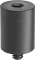
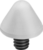
Cone Supports
 |
 |
Dia., mm | Ht., mm | Thread Lg., mm | Material | Each | |||||||||||||||||||||||||||||||||||||||||||||||||||||||||||||||||||||||||||||||||||||||||||||||
|---|---|---|---|---|---|---|---|---|---|---|---|---|---|---|---|---|---|---|---|---|---|---|---|---|---|---|---|---|---|---|---|---|---|---|---|---|---|---|---|---|---|---|---|---|---|---|---|---|---|---|---|---|---|---|---|---|---|---|---|---|---|---|---|---|---|---|---|---|---|---|---|---|---|---|---|---|---|---|---|---|---|---|---|---|---|---|---|---|---|---|---|---|---|---|---|---|---|---|---|
M6 × 1 mm Threads | |||||||||||||||||||||||||||||||||||||||||||||||||||||||||||||||||||||||||||||||||||||||||||||||||||
| 16 | 13 | 9.6 | Nylon | 1409N71 | 00000 | ||||||||||||||||||||||||||||||||||||||||||||||||||||||||||||||||||||||||||||||||||||||||||||||
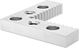
Positioners
 |  |
Slots, mm | |||||||||||||||||||||||||||||||||||||||||||||||||||||||||||||||||||||||||||||||||||||||||||||||||||
|---|---|---|---|---|---|---|---|---|---|---|---|---|---|---|---|---|---|---|---|---|---|---|---|---|---|---|---|---|---|---|---|---|---|---|---|---|---|---|---|---|---|---|---|---|---|---|---|---|---|---|---|---|---|---|---|---|---|---|---|---|---|---|---|---|---|---|---|---|---|---|---|---|---|---|---|---|---|---|---|---|---|---|---|---|---|---|---|---|---|---|---|---|---|---|---|---|---|---|---|
Lg., mm | Wd., mm | Thk., mm | Lg. | Wd. | Number of Holes | Material | Includes | Each | |||||||||||||||||||||||||||||||||||||||||||||||||||||||||||||||||||||||||||||||||||||||||||
M6 Hole Thread Size | |||||||||||||||||||||||||||||||||||||||||||||||||||||||||||||||||||||||||||||||||||||||||||||||||||
| 75 | 25 | 10 | 30 | 6.5 | 1 | Steel | Two M6 Knurled Knobs | 1409N74 | 000000 | ||||||||||||||||||||||||||||||||||||||||||||||||||||||||||||||||||||||||||||||||||||||||||
Trays
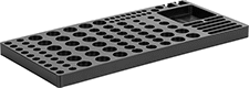 |
Lg., mm | Wd., mm | Ht., mm | Material | Each | |||||||||||||||||||||||||||||||||||||||||||||||||||||||||||||||||||||||||||||||||||||||||||||||
|---|---|---|---|---|---|---|---|---|---|---|---|---|---|---|---|---|---|---|---|---|---|---|---|---|---|---|---|---|---|---|---|---|---|---|---|---|---|---|---|---|---|---|---|---|---|---|---|---|---|---|---|---|---|---|---|---|---|---|---|---|---|---|---|---|---|---|---|---|---|---|---|---|---|---|---|---|---|---|---|---|---|---|---|---|---|---|---|---|---|---|---|---|---|---|---|---|---|---|---|
For M6 Thread | |||||||||||||||||||||||||||||||||||||||||||||||||||||||||||||||||||||||||||||||||||||||||||||||||||
| 432 | 203 | 25 | Acetal | 1409N65 | 0000000 | ||||||||||||||||||||||||||||||||||||||||||||||||||||||||||||||||||||||||||||||||||||||||||||||
Threaded Locating and Support Buttons
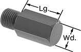 | 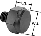 |
Flat Head |
Thread | |||||||||||||||||||||||||||||||||||||||||||||||||||||||||||||||||||||||||||||||||||||||||||||||||||
|---|---|---|---|---|---|---|---|---|---|---|---|---|---|---|---|---|---|---|---|---|---|---|---|---|---|---|---|---|---|---|---|---|---|---|---|---|---|---|---|---|---|---|---|---|---|---|---|---|---|---|---|---|---|---|---|---|---|---|---|---|---|---|---|---|---|---|---|---|---|---|---|---|---|---|---|---|---|---|---|---|---|---|---|---|---|---|---|---|---|---|---|---|---|---|---|---|---|---|---|
Lg., mm | Wd., mm | Size | Lg., mm | Lg. Tolerance, mm | Shape | Specs. Met | Each | ||||||||||||||||||||||||||||||||||||||||||||||||||||||||||||||||||||||||||||||||||||||||||||
Steel with Flat Head | |||||||||||||||||||||||||||||||||||||||||||||||||||||||||||||||||||||||||||||||||||||||||||||||||||
| 10 | 10 | M6 × 1 mm | 11 | -0.2 to 0.2 | Hex | DIN 6320 | 3078N11 | 00000 | |||||||||||||||||||||||||||||||||||||||||||||||||||||||||||||||||||||||||||||||||||||||||||
Clamps for Parts Inspection
 |
With a light yet sturdy hold, these clamps help you keep workpieces in place hands-free for measuring and inspecting. Thread them right into your fixturing surface, whether it’s a plate, tower, or table. Because they apply less pressure than machining clamps, they won’t distort your parts, so you can take accurate measurements. While these clamps aren’t sturdy enough for use in machining, you can still use them for light fabrication work, such as laser engraving.
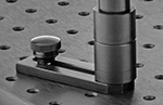
Hold-Down Clamps
 |
Tension Spring |
 |
Thumb Screw |
 |
Squeeze Tabs |
Hold-down clamps secure parts from the top.
Tension Spring—Tension spring clamps are the most common type of clamp. Slide the arm down the shaft until it touches the top of your workpiece. Since you apply pressure directly, using too much force might move your part.
Thumb Screw—Clamps with a thumb screw give you more control over the pressure you apply on a workpiece than tension spring clamps. Twisting the screw moves the clamp up or down in small increments, so they’re less likely to dent or scratch your workpiece. The knurled head on the screw is slip resistant, letting you make precise turns with reliable grip.
Squeeze Tabs—Clamps with squeeze tabs on the back are best for supporting delicate parts. They have the lightest touch of any clamps we offer, because the tension is held in the tabs rather than the clamp itself. Press the tabs together like a clothespin and rotate the clamp where you need it.
Clamps | Replacement Mounting Shafts | Replacement Clamp Arms | |||||||||||||||||||||||||||||||||||||||||||||||||||||||||||||||||||||||||||||||||||||||||||||||||
|---|---|---|---|---|---|---|---|---|---|---|---|---|---|---|---|---|---|---|---|---|---|---|---|---|---|---|---|---|---|---|---|---|---|---|---|---|---|---|---|---|---|---|---|---|---|---|---|---|---|---|---|---|---|---|---|---|---|---|---|---|---|---|---|---|---|---|---|---|---|---|---|---|---|---|---|---|---|---|---|---|---|---|---|---|---|---|---|---|---|---|---|---|---|---|---|---|---|---|---|
Reach Lg., mm | Ht., mm | Thread Lg., mm | Material | Each | Each | Each | |||||||||||||||||||||||||||||||||||||||||||||||||||||||||||||||||||||||||||||||||||||||||||||
Tension Spring | |||||||||||||||||||||||||||||||||||||||||||||||||||||||||||||||||||||||||||||||||||||||||||||||||||
M6 × 1 mm Threads | |||||||||||||||||||||||||||||||||||||||||||||||||||||||||||||||||||||||||||||||||||||||||||||||||||
| 21 | 50 | 6.2 | Aluminum | 1337N34 | 000000 | ——— | 0 | ——— | 0 | ||||||||||||||||||||||||||||||||||||||||||||||||||||||||||||||||||||||||||||||||||||||||||
| 38 | 75 | 6.2 | Aluminum | 1337N32 | 00000 | ——— | 0 | ——— | 0 | ||||||||||||||||||||||||||||||||||||||||||||||||||||||||||||||||||||||||||||||||||||||||||
| 58 | 75 | 6.2 | Aluminum | 1337N33 | 00000 | ——— | 0 | ——— | 0 | ||||||||||||||||||||||||||||||||||||||||||||||||||||||||||||||||||||||||||||||||||||||||||
Thumb Screw | |||||||||||||||||||||||||||||||||||||||||||||||||||||||||||||||||||||||||||||||||||||||||||||||||||
M6 × 1 mm Threads | |||||||||||||||||||||||||||||||||||||||||||||||||||||||||||||||||||||||||||||||||||||||||||||||||||
| 40 | 38 | 9.5 | Aluminum | 6203N14 | 00000 | ——— | 0 | ——— | 0 | ||||||||||||||||||||||||||||||||||||||||||||||||||||||||||||||||||||||||||||||||||||||||||
| 76 | 63 | 6.4 | Aluminum | 6203N15 | 00000 | ——— | 0 | ——— | 0 | ||||||||||||||||||||||||||||||||||||||||||||||||||||||||||||||||||||||||||||||||||||||||||
| 112 | 89 | 9.5 | Aluminum | 6203N16 | 000000 | ——— | 0 | ——— | 0 | ||||||||||||||||||||||||||||||||||||||||||||||||||||||||||||||||||||||||||||||||||||||||||
Squeeze Tabs | |||||||||||||||||||||||||||||||||||||||||||||||||||||||||||||||||||||||||||||||||||||||||||||||||||
M6 × 1 mm Threads | |||||||||||||||||||||||||||||||||||||||||||||||||||||||||||||||||||||||||||||||||||||||||||||||||||
| 83 | 76 | 9.5 | Plastic | 6203N22 | 00000 | 6203N19 | 000000 | 6203N17 | 000000 | ||||||||||||||||||||||||||||||||||||||||||||||||||||||||||||||||||||||||||||||||||||||||||
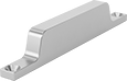
Side Clamps
Lg., mm | Wd., mm | Ht., mm | Thread Lg., mm | Material | Each | ||||||||||||||||||||||||||||||||||||||||||||||||||||||||||||||||||||||||||||||||||||||||||||||
|---|---|---|---|---|---|---|---|---|---|---|---|---|---|---|---|---|---|---|---|---|---|---|---|---|---|---|---|---|---|---|---|---|---|---|---|---|---|---|---|---|---|---|---|---|---|---|---|---|---|---|---|---|---|---|---|---|---|---|---|---|---|---|---|---|---|---|---|---|---|---|---|---|---|---|---|---|---|---|---|---|---|---|---|---|---|---|---|---|---|---|---|---|---|---|---|---|---|---|---|
M6 × 1 mm Threads | |||||||||||||||||||||||||||||||||||||||||||||||||||||||||||||||||||||||||||||||||||||||||||||||||||
| 77 | 66 | 13 | 19 | Plastic | 6203N24 | 000000 | |||||||||||||||||||||||||||||||||||||||||||||||||||||||||||||||||||||||||||||||||||||||||||||
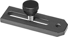
Positioning Clamps
 |
Opening, mm | |||||||||||||||||||||||||||||||||||||||||||||||||||||||||||||||||||||||||||||||||||||||||||||||||||
|---|---|---|---|---|---|---|---|---|---|---|---|---|---|---|---|---|---|---|---|---|---|---|---|---|---|---|---|---|---|---|---|---|---|---|---|---|---|---|---|---|---|---|---|---|---|---|---|---|---|---|---|---|---|---|---|---|---|---|---|---|---|---|---|---|---|---|---|---|---|---|---|---|---|---|---|---|---|---|---|---|---|---|---|---|---|---|---|---|---|---|---|---|---|---|---|---|---|---|---|
Reach Lg., mm | Min. | Max. | Lg., mm | Wd., mm | Ht., mm | Thread Lg., mm | Material | Pair | |||||||||||||||||||||||||||||||||||||||||||||||||||||||||||||||||||||||||||||||||||||||||||
M6 × 1 mm Threads | |||||||||||||||||||||||||||||||||||||||||||||||||||||||||||||||||||||||||||||||||||||||||||||||||||
| 19 | 11 | 57 | 92 | 12.7 | 63 | 6.4 | Aluminum | 6203N26 | 0000000 | ||||||||||||||||||||||||||||||||||||||||||||||||||||||||||||||||||||||||||||||||||||||||||
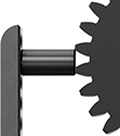
Threaded Hole Location Gauges
Thread Size | Thread Type | Hardness | Material | Each | ||
|---|---|---|---|---|---|---|
| M6 × 1 mm | Metric | Rockwell C60 | Tool Steel | 6648N18 | 0000000 |
Fixture Plates
Fixture Plates
 |
Anodized Aluminum—Anodized aluminum plates are often used with coordinate measuring machines (CMMs) and optical comparators. The coating protects them from scratches and wear, even when you’re working with heavy parts.
Quick-Change Adapters
 |
Quick-change adapters fasten to the side of plates, converting them into quick-change fixture plates. Rather than having to clamp or bolt plates down, adapters let you snap them in and out of a magnetic mounting rail.
Magnetic Mount | Bolt-On Mount | ||||||||||||
|---|---|---|---|---|---|---|---|---|---|---|---|---|---|
Lg., mm | Wd., mm | Thk., mm | Max. Magnetic Pull, lbf | No. of Mounting Edges | Mounting Fasteners Included | No. of Mounting Holes | For Mounting Fastener Thread Size | Mounting Hole Ctr.-to-Ctr., mm | Material | Each | |||
| 180 | 30 | 13 | 3.5 | 1 | Yes | 2 | M6 | 147 | Anodized Aluminum | 6364N21 | 0000000 | ||
Swiveling Locating and Support Buttons
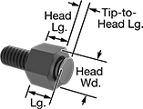 |
The swiveling tip supports uneven and angled surfaces on workpieces and fixtures. These buttons screw into a threaded hole. Also known as rest buttons.
Head, mm | Thread | ||||||||||||||||||||||||||||||||||||||||||||||||||||||||||||||||||||||||||||||||||||||||||||||||||
|---|---|---|---|---|---|---|---|---|---|---|---|---|---|---|---|---|---|---|---|---|---|---|---|---|---|---|---|---|---|---|---|---|---|---|---|---|---|---|---|---|---|---|---|---|---|---|---|---|---|---|---|---|---|---|---|---|---|---|---|---|---|---|---|---|---|---|---|---|---|---|---|---|---|---|---|---|---|---|---|---|---|---|---|---|---|---|---|---|---|---|---|---|---|---|---|---|---|---|---|
Tip Dia., mm | Lg. | Wd. | Tip-to-Head Lg., mm | Lg., mm | Size | Lg., mm | Range of Motion | Head Lg. Tolerance, mm | Load Cap., lb. | Tip Material | Each | ||||||||||||||||||||||||||||||||||||||||||||||||||||||||||||||||||||||||||||||||||||||||
Steel | |||||||||||||||||||||||||||||||||||||||||||||||||||||||||||||||||||||||||||||||||||||||||||||||||||
| 8 | 8 | 10 | 2 | 10 | M6 × 1 mm | 12 | 28° | -0.05 to 0.05 | 2,050 | Stainless Steel | 1417N17 | 000000 | |||||||||||||||||||||||||||||||||||||||||||||||||||||||||||||||||||||||||||||||||||||||
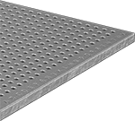
Quick-Change Fixture Plates
Fixture Plates
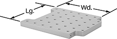 |
1 Mounting Edge |
Fixture plates hold components such as towers, clamps, and standoffs in the evenly spaced holes to raise and position parts.
Holes | |||||||||||||||||||||||||||||||||||||||||||||||||||||||||||||||||||||||||||||||||||||||||||||||||||
|---|---|---|---|---|---|---|---|---|---|---|---|---|---|---|---|---|---|---|---|---|---|---|---|---|---|---|---|---|---|---|---|---|---|---|---|---|---|---|---|---|---|---|---|---|---|---|---|---|---|---|---|---|---|---|---|---|---|---|---|---|---|---|---|---|---|---|---|---|---|---|---|---|---|---|---|---|---|---|---|---|---|---|---|---|---|---|---|---|---|---|---|---|---|---|---|---|---|---|---|
Lg., mm | Wd., mm | Thk., mm | Parallel Tolerance, mm | No. of | Ctr.-to-Ctr., mm | Max. Magnetic Pull, lbf | Material | Each | |||||||||||||||||||||||||||||||||||||||||||||||||||||||||||||||||||||||||||||||||||||||||||
1 Mounting Edge—M6 Hole Thread Size | |||||||||||||||||||||||||||||||||||||||||||||||||||||||||||||||||||||||||||||||||||||||||||||||||||
| 180 | 180 | 13 | 0.127 | 81 | 20 | 3.5 | Anodized Aluminum | 6368N23 | 0000000 | ||||||||||||||||||||||||||||||||||||||||||||||||||||||||||||||||||||||||||||||||||||||||||
| 180 | 360 | 13 | 0.127 | 162 | 20 | 3.5 | Anodized Aluminum | 6368N24 | 000000 | ||||||||||||||||||||||||||||||||||||||||||||||||||||||||||||||||||||||||||||||||||||||||||
| 360 | 360 | 13 | 0.127 | 324 | 20 | 3.5 | Anodized Aluminum | 6368N25 | 000000 | ||||||||||||||||||||||||||||||||||||||||||||||||||||||||||||||||||||||||||||||||||||||||||
| 360 | 540 | 13 | 0.127 | 486 | 20 | 3.5 | Anodized Aluminum | 6368N26 | 00000000 | ||||||||||||||||||||||||||||||||||||||||||||||||||||||||||||||||||||||||||||||||||||||||||
Corner Plates
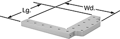 |
Corner plates make it easy for your CMM to find a workpiece since they act as a repeatable stop. The negative space gives you access underneath parts that are propped up.
Holes | |||||||||||||||||||||||||||||||||||||||||||||||||||||||||||||||||||||||||||||||||||||||||||||||||||
|---|---|---|---|---|---|---|---|---|---|---|---|---|---|---|---|---|---|---|---|---|---|---|---|---|---|---|---|---|---|---|---|---|---|---|---|---|---|---|---|---|---|---|---|---|---|---|---|---|---|---|---|---|---|---|---|---|---|---|---|---|---|---|---|---|---|---|---|---|---|---|---|---|---|---|---|---|---|---|---|---|---|---|---|---|---|---|---|---|---|---|---|---|---|---|---|---|---|---|---|
Lg., mm | Wd., mm | Thk., mm | Parallel Tolerance, mm | No. of | Ctr.-to-Ctr., mm | Max. Magnetic Pull, lbf | Material | Each | |||||||||||||||||||||||||||||||||||||||||||||||||||||||||||||||||||||||||||||||||||||||||||
1 Mounting Edge—M6 Hole Thread Size | |||||||||||||||||||||||||||||||||||||||||||||||||||||||||||||||||||||||||||||||||||||||||||||||||||
| 180 | 180 | 13 | 0.127 | 22 | 20 | 3.5 | Anodized Aluminum | 6368N31 | 0000000 | ||||||||||||||||||||||||||||||||||||||||||||||||||||||||||||||||||||||||||||||||||||||||||
