


Filter by
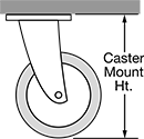
For Caster Mount Height

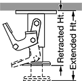
Retracted Height
Extended Height
Height
Weight Capacity
Mounting Location
Brake Retraction Pedal Location
Overall Height
Export Control Classification Number (ECCN)
DFARS Specialty Metals
Working Orientation
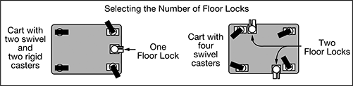
Floor Locks
 |
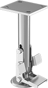
Brake Retraction Pedal on Both Sides with Pivoting Base
 |  |  | 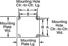 |
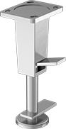
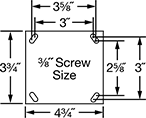
Mounting Plate Style 1 |
Ht. | Mounting Plate | Mounting Hole Ctr.-to-Ctr. | |||||||||||||||
|---|---|---|---|---|---|---|---|---|---|---|---|---|---|---|---|---|---|
For Caster Mount Ht. | Extended | Retracted | Clearance | Style | Lg. | Wd. | Lg. (A) | Lg. (B) | Wd. (A) | Wd. (B) | Mounting Fasteners Included | For Screw Size | Color | Each | |||
Painted Iron | |||||||||||||||||
| 5 5/8" to 5 7/8" | 5 5/8" | 4 9/16" | 1 5/16" | 1 | 4 13/16" | 4 1/4" | 3 5/8" | 3" | 3" | 2 5/8" | No | 3/8" | Gray | 22845T44 | 0000000 | ||
| 7 1/4" to 7 1/2" | 7 1/2" | 6" | 1 3/4" | 1 | 6 1/2" | 4 3/4" | 5 1/4" | 4 15/16" | 3 3/8" | 2 7/16" | No | 1/2" | Gray | 22845T45 | 000000 | ||
| 10 1/4" to 10 5/8" | 10 1/4" | 9 1/8" | 1 3/8" | 1 | 6 1/2" | 4 3/4" | 5 1/4" | 4 15/16" | 3 3/8" | 2 7/16" | No | 1/2" | Gray | 22845T46 | 000000 | ||
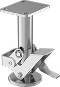
Brake Retraction Pedal on Both Sides
 |
| |
| 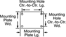 |
Mounting Plate Style 1 | Mounting Plate Style 2 |
Ht. | Mounting Plate | Mounting Hole Ctr.-to-Ctr. | ||||||||||||||||
|---|---|---|---|---|---|---|---|---|---|---|---|---|---|---|---|---|---|---|
For Caster Mount Ht. | Extended | Retracted | Clearance | Style | Lg. | Wd. | Lg. | Wd. | Lg. (A) | Lg. (B) | Wd. (A) | Wd. (B) | Mounting Fasteners Included | For Screw Size | Each | |||
Zinc-Plated Steel | ||||||||||||||||||
| 5 5/8" | 5 7/8" | 4 7/8" | 1" | 1 | 4 1/2" | 4" | — | — | 3 5/8" | 3" | 3" | 2 5/8" | No | 3/8" | 2728T21 | 000000 | ||
| 6 1/2" | 6 3/4" | 5 3/4" | 1" | 1 | 4 1/2" | 4" | — | — | 3 5/8" | 3" | 3" | 2 5/8" | No | 3/8" | 2728T22 | 00000 | ||
| 7 1/4" | 7 1/2" | 6 1/2" | 1" | 1 | 4 1/2" | 4" | — | — | 3 5/8" | 3" | 3" | 2 5/8" | No | 3/8" | 2728T23 | 00000 | ||
| 7 3/8" | 7 5/8" | 6 3/8" | 1 1/4" | 2 | 5 1/2" | 5" | 4 1/2" | 4 1/8" | — | — | — | — | No | 3/8" | 2728T32 | 000000 | ||
| 7 1/2" | 7 3/4" | 6 1/2" | 1 1/4" | 1 | 6 1/4" | 4 1/2" | — | — | 5 1/4" | 4 15/16" | 3 3/8" | 2 7/16" | No | 1/2" | 2728T29 | 000000 | ||
| 7 1/2" | 7 3/4" | 6 3/4" | 1" | 1 | 4 1/2" | 4" | — | — | 3 5/8" | 3" | 3" | 2 5/8" | No | 3/8" | 2728T24 | 00000 | ||
| 9 1/2" | 9 3/4" | 8 1/2" | 1 1/4" | 2 | 5 1/2" | 5" | 4 1/2" | 4 1/8" | — | — | — | — | No | 3/8" | 2728T33 | 000000 | ||
| 9 1/2" | 9 3/4" | 8 3/4" | 1" | 1 | 4 1/2" | 4" | — | — | 3 5/8" | 3" | 3" | 2 5/8" | No | 3/8" | 2728T25 | 00000 | ||
| 10 1/8" | 10 3/8" | 9 1/8" | 1 1/4" | 1 | 6 1/4" | 4 1/2" | — | — | 5 1/4" | 4 15/16" | 3 3/8" | 2 7/16" | No | 1/2" | 2728T31 | 000000 | ||
| 10 1/8" | 10 3/8" | 9 3/8" | 1" | 1 | 4 1/2" | 4" | — | — | 3 5/8" | 3" | 3" | 2 5/8" | No | 3/8" | 2728T26 | 00000 | ||
| 10 1/2" | 10 3/4" | 9 1/2" | 1 1/4" | 1 | 7 1/4" | 5" | — | — | 6 1/8" | 5 1/4" | 4 1/8" | 3 3/8" | No | 1/2" | 2728T28 | 000000 | ||
304 Stainless Steel | ||||||||||||||||||
| 5 5/8" | 5 5/8" | 4 1/2" | 1 1/8" | 1 | 4 1/2" | 4" | — | — | 3 5/8" | 3" | 3" | 2 5/8" | No | 3/8" | 2338T46 | 000000 | ||
| 6 1/2" | 6 1/2" | 5 3/8" | 1 1/8" | 1 | 4 1/2" | 4" | — | — | 3 5/8" | 3" | 3" | 2 5/8" | No | 3/8" | 2338T49 | 000000 | ||
| 7 1/2" | 7 1/2" | 6 1/2" | 1" | 1 | 4 1/2" | 4" | — | — | 3 5/8" | 3" | 3" | 2 5/8" | No | 3/8" | 2338T47 | 000000 | ||
Brake Retraction Pedal on One Side
 | | | |
Mounting Plate Style 1 |
Ht. | Mounting Plate | Mounting Hole Ctr.-to-Ctr. | ||||||||||||||
|---|---|---|---|---|---|---|---|---|---|---|---|---|---|---|---|---|
For Caster Mount Ht. | Extended | Retracted | Clearance | Style | Lg. | Wd. | Lg. (A) | Lg. (B) | Wd. (A) | Wd. (B) | Mounting Fasteners Included | For Screw Size | Each | |||
Zinc-Plated Steel | ||||||||||||||||
| 5 5/16" to 5 1/2" | 5 5/8" | 4 7/8" | 3/4" | 1 | 4 5/8" | 3 3/4" | 3 5/8" | 3" | 3" | 2 5/8" | No | 3/8" | 2478T61 | 000000 | ||
| 5 7/16" to 5 5/8" | 5 3/4" | 5" | 3/4" | 1 | 4 5/8" | 3 3/4" | 3 5/8" | 3" | 3" | 2 5/8" | No | 3/8" | 2478T65 | 00000 | ||
| 6 3/16" to 6 3/8" | 6 1/2" | 5 3/4" | 3/4" | 1 | 4 5/8" | 3 3/4" | 3 5/8" | 3" | 3" | 2 5/8" | No | 3/8" | 2478T62 | 00000 | ||
| 6 7/16" to 6 5/8" | 6 3/4" | 6" | 3/4" | 1 | 4 5/8" | 3 3/4" | 3 5/8" | 3" | 3" | 2 5/8" | No | 3/8" | 2478T66 | 00000 | ||
| 6 15/16" to 7 1/8" | 7 1/4" | 6 1/2" | 3/4" | 1 | 4 5/8" | 3 3/4" | 3 5/8" | 3" | 3" | 2 5/8" | No | 3/8" | 2478T63 | 00000 | ||
| 7 7/16" to 7 5/8" | 7 3/4" | 7" | 3/4" | 1 | 4 5/8" | 3 3/4" | 3 5/8" | 3" | 3" | 2 5/8" | No | 3/8" | 2478T67 | 00000 | ||
| 9 7/16" to 9 5/8" | 9 3/4" | 9" | 3/4" | 1 | 4 5/8" | 3 3/4" | 3 5/8" | 3" | 3" | 2 5/8" | No | 3/8" | 2478T64 | 00000 | ||
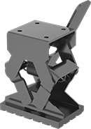
Top Brake Retraction Pedal
 |
| |
| |
Mounting Plate Style 2 |
Ht. | Mounting Plate | Mounting Hole Ctr.-to-Ctr. | |||||||||||||
|---|---|---|---|---|---|---|---|---|---|---|---|---|---|---|---|
For Caster Mount Ht. | Extended | Retracted | Clearance | Style | Lg. | Wd. | Lg. | Wd. | Mounting Fasteners Included | For Screw Size | Color | Each | |||
Painted Steel | |||||||||||||||
| 5" to 7" | 7 1/4" | 3 3/8" | 3 7/8" | 2 | 4" | 4" | 2 5/8" | 2 3/8" | No | 3/8" | Black | 2675T11 | 0000000 | ||
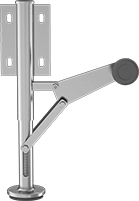
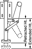
Leveling Jacks
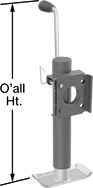 | 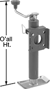 |  |  |
Side Handle Style A | Top Handle Style A | Side Handle Style B | Top Handle Style B |
 |  |  | |
Top Handle Style C | Top Handle Style D | Top Handle Style E |
Mounting | |||||||||||||||||
|---|---|---|---|---|---|---|---|---|---|---|---|---|---|---|---|---|---|
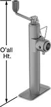
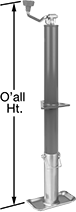
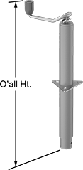
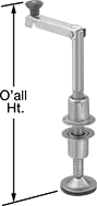
Style | Weight Capacity | Ht. | Max. Lift | Overall Ht. | Handle Lg. | Body Material | For Hole Dia. | Fasteners Included | No. of Holes | Hole Dia. | Hole Lg. | Hole Wd. | Features | Each | |||
Weld On Side Mount with Rectangular Mounting Plate | |||||||||||||||||
Side Handle | |||||||||||||||||
| A | 1 ton/2,000 lb. | 10 7/8" to 20 7/8" | 10" | 22 3/4" | 5 7/8" | Steel | — | — | — | — | — | — | Foot Plate | 2963T44 | 0000000 | ||
| A | 2 1/2 ton/5,000 lb. | 10 3/8" to 20 3/8" | 10" | 22 7/8" | 6 1/2" | Steel | — | — | — | — | — | — | Foot Plate | 2963T48 | 00000 | ||
| A | 2 1/2 ton/5,000 lb. | 15 3/8" to 30 3/8" | 15" | 27 7/8" | 6 1/2" | Steel | — | — | — | — | — | — | Foot Plate | 2963T49 | 000000 | ||
Top Handle | |||||||||||||||||
| A | 2 1/2 ton/5,000 lb. | 14 1/2" to 29 1/2" | 15" | 27 1/2" | 7 5/8" | Steel | — | — | — | — | — | — | Foot Plate | 2963T35 | 000000 | ||
Weld On Side Mount with Square Mounting Plate | |||||||||||||||||
Side Handle | |||||||||||||||||
| A | 1 ton/2,000 lb. | 15" to 30 1/2" | 15 1/2" | 32 3/4" | 6 1/8" | Steel | — | — | — | — | — | — | Foot Plate | 2963T52 | 000000 | ||
Top Handle | |||||||||||||||||
| A | 1 ton/2,000 lb. | 14 3/4" to 29 3/4" | 15" | 30" | 6" | Steel | — | — | — | — | — | — | Foot Plate | 2963T51 | 00000 | ||
Weld On Side Mount with Tubular Mounting Plate | |||||||||||||||||
Side Handle | |||||||||||||||||
| B | 1 ton/2,000 lb. | 10 7/8" to 20 7/8" | 10" | 23" | 5 7/8" | Steel | — | — | — | — | — | — | Foot Plate | 2963T71 | 000000 | ||
| B | 1 ton/2,000 lb. | 15" to 30 1/2" | 15 1/2" | 32 3/4" | 6 1/8" | Steel | — | — | — | — | — | — | Foot Plate | 2963T53 | 000000 | ||
| B | 2 1/2 ton/5,000 lb. | 10 1/2" to 20 1/2" | 10" | 23" | 6 1/2" | Steel | — | — | — | — | — | — | Foot Plate | 2963T73 | 000000 | ||
| B | 2 1/2 ton/5,000 lb. | 15 1/2" to 30 1/2" | 15" | 28" | 6 1/2" | Steel | — | — | — | — | — | — | Foot Plate | 2963T74 | 000000 | ||
| B | 3 1/2 ton/7,000 lb. | 11" to 21" | 10" | 25 5/8" | 8 1/2" | Steel | — | — | — | — | — | — | Foot Plate | 2963T75 | 000000 | ||
| B | 5 ton/10,000 lb. | 17" to 29 5/8" | 12 5/8" | 39 1/2" | 13 1/2" | Steel | — | — | — | — | — | — | Foot Plate | 2963T81 | 000000 | ||
Top Handle | |||||||||||||||||
| B | 2 1/2 ton/5,000 lb. | 11 1/4" to 21 1/4" | 10" | 18" | 7 5/8" | Steel | — | — | — | — | — | — | Foot Plate | 2963T18 | 000000 | ||
Bolt On/Through Hole with Triangular Mounting Plate | |||||||||||||||||
Top Handle | |||||||||||||||||
| C | 2 1/2 ton/5,000 lb. | 10 1/8" to 25 1/8" | 15" | 24 1/8" | 7 5/8" | Steel | 2 1/4" | No | 3 | — | 7/16" | 13/16" | Foot Plate | 2933T61 | 00000 | ||
Bolt On/Weld On/Through Hole with Triangular Mounting Plate | |||||||||||||||||
Top Handle | |||||||||||||||||
| D | 2 1/2 ton/5,000 lb. | 10 7/8" to 25 7/8" | 15" | 24 3/8" | 7 5/8" | Steel | 2 1/4" | No | 3 | — | 7/16" | 13/16" | — | 2933T35 | 000000 | ||
Bolt On/Through Hole with Round Mounting Plate | |||||||||||||||||
Top Handle | |||||||||||||||||
| E | 2 1/2 ton/5,000 lb. | 4 1/2" to 13 1/2" | 9" | 19 3/4" | 8 3/4" | Steel | 1 1/4" | No | 6 | 1/4" | — | — | Foot Plate, Slip-Resistant Rubber Pad | 2953T1 | 000000 | ||
| E | 2 1/2 ton/5,000 lb. | 4 1/2" to 21 1/2" | 17" | 27 3/4" | 8 7/8" | Steel | 1 1/4" | No | 6 | 1/4" | — | — | Foot Plate, Slip-Resistant Rubber Pad | 2953T2 | 00000 | ||
| E | 2 1/2 ton/5,000 lb. | 4 1/2" to 25 1/2" | 21" | 31 3/4" | 8 3/4" | Steel | 1 1/4" | No | 6 | 1/4" | — | — | Foot Plate, Slip-Resistant Rubber Pad | 2953T3 | 000000 | ||
Ladder Levelers
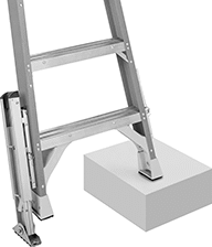 | 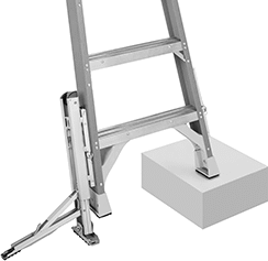 |
Levelers with Foot Lock and Swivel Shoe | Levelers with Foot Lock, Stabilizing Arm, and Swivel Shoe |
Ht. | |||||||||||
|---|---|---|---|---|---|---|---|---|---|---|---|
For Ladder Type | For Rail Material | For Wt. Cap., lb. | Material | Retracted | Extended | Ht. Adjustment Increments | Specs. Met | Each | |||
Levelers with Foot Lock and Swivel Shoe | |||||||||||
| Extension, Step, Straight | Aluminum, Fiberglass | 250, 300, 375 | Aluminum | 19 1/2" | 29 1/2" | 3/16" | Cal/OSHA Compliant Title 8 Section 3276, OSHA Compliant 29 CFR 1910.23, OSHA Compliant 29 CFR 1926.1053, ANSI-ASC A14.5 | 7948T65 | 0000000 | ||
Levelers with Foot Lock, Stabilizing Arm, and Swivel Shoe | |||||||||||
| Extension, Step, Straight | Aluminum, Fiberglass | 250, 300, 375 | Aluminum | 19 1/2" | 29 1/2" | 3/16" | Cal/OSHA Compliant Title 8 Section 3276, OSHA Compliant 29 CFR 1910.23, OSHA Compliant 29 CFR 1926.1053, ANSI-ASC A14.5 | 7948T111 | 000000 | ||
Adjustable-Height Floor Locks
Brake Retraction Pedal on One Side
|  |
| | |  |
Mounting Plate Style 1 |
Mounting Plate | Mounting Hole Ctr.-to-Ctr. | |||||||||||||
|---|---|---|---|---|---|---|---|---|---|---|---|---|---|---|
For Caster Mount Ht. | Ht. Range | Clearance | Lg. | Wd. | Lg. (A) | Lg. (B) | Wd. (A) | Wd. (B) | Mounting Fasteners Included | For Screw Size | Each | |||
Aluminum | ||||||||||||||
| 6 1/2" to 7 1/2" | 5 1/2" to 8" | 2 1/2" | 4 3/4" | 3 3/4" | 3 5/8" | 3" | 3" | 2 5/8" | No | 3/8" | 2510T17 | 0000000 | ||
| 8" to 10 1/2" | 7" to 11" | 4" | 4 3/4" | 3 3/4" | 3 5/8" | 3" | 3" | 2 5/8" | No | 3/8" | 2510T18 | 000000 | ||
Scaffold Leveling Jacks
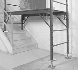 | 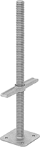 |
Swap these jacks with the base plates on your scaffold to create a level foundation on uneven ground. They adjust in increments less than an inch, so you can set each leg of your scaffold to the exact height you need. Made from galvanized steel, these jacks resist rust and hold up to outdoor use. For safety and stability, the top 6" of the threaded stud slides into the scaffold frame and isn’t usable.
Note: Leveling jacks meet OSHA and Cal/OSHA dimensional and construction standards. Check local, state, and federal codes, including OSHA, for safe set up and operating practices.
Hollow—Hollow jacks are lighter in weight than solid jacks, so they’re easier to handle.
Overall | Base | Thread | Base Mount | ||||||||||||||||
|---|---|---|---|---|---|---|---|---|---|---|---|---|---|---|---|---|---|---|---|
Wt. Cap., lb. | Max. Lift | Ht. | Wd. | Lg. | Wd. | For ID | Material | Size | Lg. | Fasteners Included | No. of Holes | Hole Dia. | Hole Ctr.-to-Ctr. | Wt., lb. | Specs. Met | Each | |||
Hollow | |||||||||||||||||||
| 5,300 | 18" | 24" | 9 3/8" | 5 5/16" | 5 5/16" | 1 1/2" | Galvanized Steel | 1 3/8"-4 | 16 9/16" | No | 4 | 1/2" | 3 5/16" | 6 | Cal/OSHA Compliant Title 8 Section 1646, OSHA Compliant 29 CFR 1926.451 | 7819N11 | 000000 | ||
Solid | |||||||||||||||||||
| 15,500 | 18" | 24" | 9 3/8" | 5 5/16" | 5 5/16" | 1 1/2" | Galvanized Steel | 1 3/8"-4 | 16 9/16" | No | 4 | 1/2" | 3 5/16" | 11 | Cal/OSHA Compliant Title 8 Section 1646, OSHA Compliant 29 CFR 1926.451 | 7819N12 | 00000 | ||
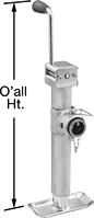
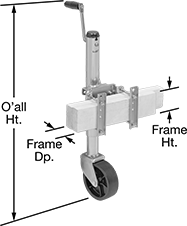
Leveling Jacks with Wheel
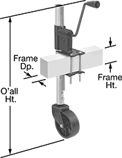 | 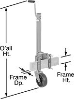 |  | 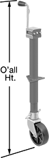 |
Style A | Style B | Style C | Style D |
For Frame | Mounting | Mounting Plate | ||||||||||||||||||
|---|---|---|---|---|---|---|---|---|---|---|---|---|---|---|---|---|---|---|---|---|
Style | Weight Capacity | Ht. | Max. Lift | Overall Ht. | Ht. | Dp. | Handle Lg. | Body Material | For Hole Dia. | Fasteners Included | No. of Holes | Hole Lg. | Hole Wd. | Lg. | Wd. | Wheel Material | Each | |||
Clamp On Side Mount | ||||||||||||||||||||
| A | 1/4 ton/750 lb. | 7 1/2" to 23 1/2" | 16" | 27 7/8" | 0" to 5" | 1 7/8" to 2 7/8" | 5 1/2" | Steel | — | Yes | — | — | — | — | — | Plastic | 2958T6 | 0000000 | ||
| B | 1/2 ton/1,000 lb. | 10 13/16" to 25 1/2" | 14 11/16" | 33 7/8" | 3" to 5" | 2" to 3" | 6 1/8" | Steel | — | Yes | — | — | — | — | — | Plastic | 8792T31 | 000000 | ||
Clamp On Side Mount with Locking Pin | ||||||||||||||||||||
| C | 1/2 ton/1,200 lb. | 12 1/2" to 22 1/2" | 10" | 28 1/8" | 2" to 4" | 1 1/2" to 3" | 6" | Steel | — | Yes | — | — | — | — | — | Plastic | 8792T44 | 000000 | ||
| C | 3/4 ton/1,500 lb. | 12 7/8" to 22 7/8" | 10" | 31 5/8" | 3" to 5" | 2" to 3" | 6 1/8" | Steel | — | Yes | — | — | — | — | — | Plastic | 8792T32 | 000000 | ||
Bolt On/Through-Hole Mount | ||||||||||||||||||||
| D | 1/2 ton/1,200 lb. | 8 5/8" to 21 1/2" | 12 7/8" | 35 5/8" | — | — | 6 1/2" | Steel | 2 1/4" | No | 3 | 7/16" | 13/16" | 5 1/8" | 4 1/4" | Plastic | 2933T62 | 000000 | ||
Side-Mount Floor Locks
|  |
|  | 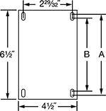 |
Ht. | Mounting Plate | Mounting Hole Ctr.-to-Ctr. | Left-Side Mount | Right-Side Mount | ||||||||||||
|---|---|---|---|---|---|---|---|---|---|---|---|---|---|---|---|---|
For Max. Caster Mount Ht. | Extended | Retracted | Clearance | Lg. | Wd. | Lg. | Wd. (A) | Wd. (B) | Mounting Fasteners Included | For Screw Size | Each | Each | ||||
Top Brake Retraction Pedal | ||||||||||||||||
Chrome-Plated Steel | ||||||||||||||||
| 11" | 11 1/8" | 8 7/8" | 2" | 4 1/2" | 6 1/2" | 2 29/32" | 4 13/32" | 3 19/32" | No | 3/8" | 27185T11 | 0000000 | 27185T121 | 0000000 | ||
