


Filter by
System of Measurement
Voltage
Maximum Rotation Speed


Bearing Type

Direction of Operation


Power
Mounting Position
Input Voltage
Speed @ Continuous Operating Torque
DFARS Specialty Metals
U.S.–Mexico–Canada Agreement (USMCA) Qualifying
Export Control Classification Number (ECCN)
Electrical Phase
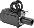
Spindle Motors
 |
 |  |
Designed to run at high speeds with very little vibration, these motors often drive smooth, steady cuts in CNC machines. They’re brushless, so they run faster, last longer, and are more efficient than brushed DC motors. They also have a higher torque-to-weight ratio. You’ll need a brushless DC motor driver (not included) to power and control these spindle motors. They’re not compatible with automatic tool changers.
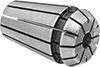
They come with an ER-11 collet for holding round-shank tools, such as router bits, drill bits, and end mills. Collets for larger shank sizes are sold separately.
Total Indicated Runout (TIR) Accuracy—Total Indicated Runout (TIR) is a measure of rotational smoothness—the lower the value, the less wobble a rotating tool will have and the more accurate it will be. When choosing a replacement spindle motor, you want one that has an equal or better TIR.
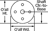
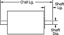
Torque, in·lbf | Overall | Shaft | Insulation | ||||||||||||||||||||||||||||||||||||||||||||||||||||||||||||||||||||||||||||||||||||||||||||||||
|---|---|---|---|---|---|---|---|---|---|---|---|---|---|---|---|---|---|---|---|---|---|---|---|---|---|---|---|---|---|---|---|---|---|---|---|---|---|---|---|---|---|---|---|---|---|---|---|---|---|---|---|---|---|---|---|---|---|---|---|---|---|---|---|---|---|---|---|---|---|---|---|---|---|---|---|---|---|---|---|---|---|---|---|---|---|---|---|---|---|---|---|---|---|---|---|---|---|---|---|
Max. Rotation Speed, rpm | Full Load Current | Wattage, kW | Max. | Continuous | Lg. | Wd. | Ht. | Dia., mm | Lg., mm | Ctr. to Base | Type | Component | Class | Max. Temp., ° F | Total Indicated Runout (TIR) Accuracy | Collet Type | Collet Sizes Included | Each | |||||||||||||||||||||||||||||||||||||||||||||||||||||||||||||||||||||||||||||||||
48V DC | |||||||||||||||||||||||||||||||||||||||||||||||||||||||||||||||||||||||||||||||||||||||||||||||||||
NEMA 24 | |||||||||||||||||||||||||||||||||||||||||||||||||||||||||||||||||||||||||||||||||||||||||||||||||||
| 14,400 | 24.9 amp | 0.211 | 0.31 | 0.1 | 6.1" | 2.4" | 2.8" | 30 | 52 | 1.19" | Solid | Motor | F | 311 | 0.0005" | ER-11 | 1/8" | 4856N11 | 0000000 | ||||||||||||||||||||||||||||||||||||||||||||||||||||||||||||||||||||||||||||||||
 |
Collet Size | Grip Range | Workpiece Dia. Tolerance | Max. Body Dia. | Approx. Dia. Compression | Overall Lg. | Material | Each | ||
|---|---|---|---|---|---|---|---|---|---|
| 1/8" | 0.109" to 0.125" | -0.0001" to 0.0001" | 0.46" | 1/64" | 0.71" | Steel | 4560N12 | 000000 | |
| 3/16" | 0.172" to 0.187" | -0.0001" to 0.0001" | 0.46" | 1/64" | 0.71" | Steel | 4560N13 | 00000 | |
| 1/4" | 0.234" to 0.250" | -0.0001" to 0.0001" | 0.46" | 1/64" | 0.71" | Steel | 4560N11 | 00000 |
DC Servomotors
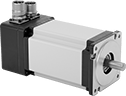 |
Often used for small automation applications, such as pick-and-place machines, these servomotors deliver lots of power in a small package. With accurate positioning and fine motor control, they create rotary motion based on signals from a drive (sold separately). The commands for speed and positioning are the same as those used for stepper motors, so you can upgrade your system without the hassle of reprogramming it. As these servomotors move, their encoder relays the shaft’s distance, direction, and speed back to the drive. The drive increases your system’s efficiency by taking the electrical signal from the encoder and dynamically adapting the motor’s movements, also accounting for inconsistent loads and unexpected forces.
Maximum Torque—Torque generally decreases as speed increases. Use a torque-speed curve to confirm which motor will work for your application. Click on a part number and select "Product Detail" to view the curve for a motor.
Servomotors | Servomotor Encoder Cords | Servomotor Power Cords | |||||||||||||||||||||||||||||||||||||||||||||||||||||||||||||||||||||||||||||||||||||||||||||||||
|---|---|---|---|---|---|---|---|---|---|---|---|---|---|---|---|---|---|---|---|---|---|---|---|---|---|---|---|---|---|---|---|---|---|---|---|---|---|---|---|---|---|---|---|---|---|---|---|---|---|---|---|---|---|---|---|---|---|---|---|---|---|---|---|---|---|---|---|---|---|---|---|---|---|---|---|---|---|---|---|---|---|---|---|---|---|---|---|---|---|---|---|---|---|---|---|---|---|---|---|
Shaft, mm | |||||||||||||||||||||||||||||||||||||||||||||||||||||||||||||||||||||||||||||||||||||||||||||||||||
Motor Frame Size | Max. Torque, in·lbf | Continuous Torque, in·lbf | Max. Rotation Speed, rpm | Current, amp | Max. Current, amp | Wattage, W | Voltage, V DC | Dia. | Lg. | No. of Counts per Rev. | Enclosure Rating | Each | Each | Each | |||||||||||||||||||||||||||||||||||||||||||||||||||||||||||||||||||||||||||||||||||||
Without Brake | |||||||||||||||||||||||||||||||||||||||||||||||||||||||||||||||||||||||||||||||||||||||||||||||||||
| 60 mm | 16.8 | 5.7 | 3,000 | 5.2 | 15.6 | 200 | 48 | 14 | 27 | 10,000 | IP65 | 5082N29 | 0000000 | 5082N102 | 0000000 | 5082N101 | 0000000 | ||||||||||||||||||||||||||||||||||||||||||||||||||||||||||||||||||||||||||||||||||
| 60 mm | 33.6 | 11.2 | 3,000 | 12 | 36 | 400 | 48 | 14 | 27 | 10,000 | IP65 | 5082N31 | 000000 | 5082N102 | 000000 | 5082N101 | 000000 | ||||||||||||||||||||||||||||||||||||||||||||||||||||||||||||||||||||||||||||||||||
| 80 mm | 61.1 | 21.2 | 3,000 | 22.5 | 56 | 750 | 48 | 19 | 37 | 10,000 | IP65 | 5082N33 | 000000 | 5082N102 | 000000 | 5082N101 | 000000 | ||||||||||||||||||||||||||||||||||||||||||||||||||||||||||||||||||||||||||||||||||
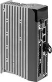 |
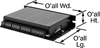
Drives have several control modes that power the motor—step and direction, position, speed, or torque. Use a computer to set motion parameters and calibrate the servomotor to your system. After initial setup, you can use a separate controller, such as a programmable logic controller (PLC), microcontroller, or indexer. A brake resistor protects the drive from regenerated electricity as the motor slows or stops.
Overall, mm | No. of Inputs/Outputs | ||||||||||||||||||||||||||||||||||||||||||||||||||||||||||||||||||||||||||||||||||||||||||||||||||
|---|---|---|---|---|---|---|---|---|---|---|---|---|---|---|---|---|---|---|---|---|---|---|---|---|---|---|---|---|---|---|---|---|---|---|---|---|---|---|---|---|---|---|---|---|---|---|---|---|---|---|---|---|---|---|---|---|---|---|---|---|---|---|---|---|---|---|---|---|---|---|---|---|---|---|---|---|---|---|---|---|---|---|---|---|---|---|---|---|---|---|---|---|---|---|---|---|---|---|---|
For Motor Frame Size | Communication Protocol | For Max. Motor Torque | Current, amp | Operating Voltage, V DC | Lg. | Wd. | Ht. | Digital Inputs | Analog Inputs | Outputs | Each | ||||||||||||||||||||||||||||||||||||||||||||||||||||||||||||||||||||||||||||||||||||||||
For 24V, 48V, and 60V DC Motor Voltage | |||||||||||||||||||||||||||||||||||||||||||||||||||||||||||||||||||||||||||||||||||||||||||||||||||
| 40 mm, 60 mm, 80 mm | — | 8.5 in·lbf to 61.1 in·lbf | 12 | 24 to 60 | 97 | 41 | 150 | 12 | 2 | 6 | 5082N35 | 0000000 | |||||||||||||||||||||||||||||||||||||||||||||||||||||||||||||||||||||||||||||||||||||||
| 40 mm, 60 mm, 80 mm | Modbus RTU | 8.5 in·lbf to 61.1 in·lbf | 12 | 24 to 60 | 97 | 41 | 150 | 12 | 2 | 6 | 5082N37 | 000000 | |||||||||||||||||||||||||||||||||||||||||||||||||||||||||||||||||||||||||||||||||||||||
| 40 mm, 60 mm, 80 mm | Modbus TCP/IP | 8.5 in·lbf to 61.1 in·lbf | 12 | 24 to 60 | 97 | 41 | 150 | 12 | 2 | 6 | 5082N36 | 000000 | |||||||||||||||||||||||||||||||||||||||||||||||||||||||||||||||||||||||||||||||||||||||
| 40 mm, 60 mm, 80 mm | EtherNet/IP | 8.5 in·lbf to 61.1 in·lbf | 12 | 24 to 60 | 97 | 41 | 150 | 12 | 2 | 6 | 5082N34 | 000000 | |||||||||||||||||||||||||||||||||||||||||||||||||||||||||||||||||||||||||||||||||||||||
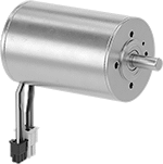
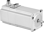
Brushless DC Motors
Round Face
 |
 |
 |
Round-face motors come with a connector that was used to test the motors during the manufacturing process. Before you can wire these motors to the terminals on their required driver, you will need to cut off the connector.
Overall | Shaft | Insulation | |||||||||||||||||||||||||||||||||||||||||||||||||||||||||||||||||||||||||||||||||||||||||||||||||
|---|---|---|---|---|---|---|---|---|---|---|---|---|---|---|---|---|---|---|---|---|---|---|---|---|---|---|---|---|---|---|---|---|---|---|---|---|---|---|---|---|---|---|---|---|---|---|---|---|---|---|---|---|---|---|---|---|---|---|---|---|---|---|---|---|---|---|---|---|---|---|---|---|---|---|---|---|---|---|---|---|---|---|---|---|---|---|---|---|---|---|---|---|---|---|---|---|---|---|---|
Speed @ Continuous Operating Torque, rpm | Max. Rotation Speed, rpm | Starting Torque, in·ozf | Full Load Current | Lg. | Wd. | Ht. | Type | Dia. | Lg. | Ctr. to Base | Class | Max. Temp., ° F | Each | ||||||||||||||||||||||||||||||||||||||||||||||||||||||||||||||||||||||||||||||||||||||
48V DC | |||||||||||||||||||||||||||||||||||||||||||||||||||||||||||||||||||||||||||||||||||||||||||||||||||
| 3,990 | 5,090 | 2,166.662 | 9.87 amp | 4 1/2" | 2" | 2" | Solid | 5/16" | 3/4" | 1.024" | F | 311 | 4853N18 | 000000000 | |||||||||||||||||||||||||||||||||||||||||||||||||||||||||||||||||||||||||||||||||||||
 |
Screw-Terminal Wire Connection |
Drivers control the speed and direction the motor spins. To program the driver, connect it to your computer with a mini USB cord and use the free downloadable software to enter your speed and acceleration parameters. No coding is necessary.
Use Driver 4853N29 with Square-Face Motors with a full load current of 1.4-4.9 amps.
Use Driver 4853N19 with Round-Face Motors with a full load current of 1.52-3.64 amps.
Use Driver 4853N21 with Round-Face Motors with a full load current of 8.96-9.87 amps.
USB | Overall | ||||||||||
|---|---|---|---|---|---|---|---|---|---|---|---|
Current, amp | Input Voltage, V DC | Connection Gender | Connection Type | Standard | Wire Connection | Lg. | Wd. | Ht. | Each | ||
| 10 | 10 to 70 | Female | Mini USB-B | 2.0 | Screw Terminal | 3.47" | 4.92" | 1.06" | 4853N21 | 0000000 | |
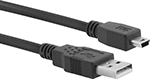 |
Connections | USB Std. | Color | Lg., ft. | Each | ||
|---|---|---|---|---|---|---|
| USB-A Male Plug × Mini USB-B Male Plug | 2.0 | Black | 6 | 4974T32 | 00000 |
Stepper Servomotors
 |
Combine the high torque at low speeds that traditional stepper motors are known for with the greater torque performance and positioning reliability of a servomotor. They create rotary motion based on signals from a drive (sold separately). As these servomotors move, their encoder relays the shaft’s distance, direction, and speed back to the drive. The drive increases your system’s efficiency by taking the electrical signal from the encoder and dynamically adapting the motor’s movements, also accounting for inconsistent loads and unexpected forces.
Maximum Holding Torque—Holding torque is the force needed to move the shaft out of position when it is stationary. Torque generally decreases as speed increases. Use a torque-speed curve to confirm which motor will work for your application. Click on a part number and select "Product Detail" to view the curve for a motor.
Servomotors | Servomotor Encoder Cords | Servomotor Power Cords | |||||||||||||||||||||||||||||||||||||||||||||||||||||||||||||||||||||||||||||||||||||||||||||||||
|---|---|---|---|---|---|---|---|---|---|---|---|---|---|---|---|---|---|---|---|---|---|---|---|---|---|---|---|---|---|---|---|---|---|---|---|---|---|---|---|---|---|---|---|---|---|---|---|---|---|---|---|---|---|---|---|---|---|---|---|---|---|---|---|---|---|---|---|---|---|---|---|---|---|---|---|---|---|---|---|---|---|---|---|---|---|---|---|---|---|---|---|---|---|---|---|---|---|---|---|
Overall | Shaft | ||||||||||||||||||||||||||||||||||||||||||||||||||||||||||||||||||||||||||||||||||||||||||||||||||
Max. Holding Torque, in·ozf | Max. Rotation Speed, rpm | Voltage, V DC | Full Step Increment | Lg. | Wd. | Ht. | Dia. | Lg. | Ctr.-to-Base Lg. | Enclosure Rating | Each | Each | Each | ||||||||||||||||||||||||||||||||||||||||||||||||||||||||||||||||||||||||||||||||||||||
NEMA 17 Frame Size | |||||||||||||||||||||||||||||||||||||||||||||||||||||||||||||||||||||||||||||||||||||||||||||||||||
| 70.8 | 1,740 | 48 | 1.8° | 4.6" | 1.7" | 2.2" | 5 mm | 22 mm | 0.83" | IP54 | 5203N11 | 0000000 | 5203N103 | 0000000 | 5203N101 | 0000000 | |||||||||||||||||||||||||||||||||||||||||||||||||||||||||||||||||||||||||||||||||||
NEMA 23 Frame Size | |||||||||||||||||||||||||||||||||||||||||||||||||||||||||||||||||||||||||||||||||||||||||||||||||||
| 113.3 | 2,720 | 48 | 1.8° | 4.8" | 2.3" | 2.7" | 1/4" | 3/4" | 1.11" | IP54 | 5203N12 | 000000 | 5203N103 | 000000 | 5203N101 | 000000 | |||||||||||||||||||||||||||||||||||||||||||||||||||||||||||||||||||||||||||||||||||
| 198.3 | 1,940 | 48 | 1.8° | 5.7" | 2.3" | 2.7" | 1/4" | 3/4" | 1.11" | IP54 | 5203N13 | 000000 | 5203N103 | 000000 | 5203N101 | 000000 | |||||||||||||||||||||||||||||||||||||||||||||||||||||||||||||||||||||||||||||||||||
NEMA 34 Frame Size | |||||||||||||||||||||||||||||||||||||||||||||||||||||||||||||||||||||||||||||||||||||||||||||||||||
| 354 | 2,130 | 48 | 1.8° | 5.5" | 3.4" | 3.9" | 11 mm | 25 mm | 1.69" | IP54 | 5203N14 | 000000 | 5203N103 | 000000 | 5203N102 | 000000 | |||||||||||||||||||||||||||||||||||||||||||||||||||||||||||||||||||||||||||||||||||
| 835.5 | 550 | 48 | 1.8° | 6.8" | 3.4" | 3.9" | 11 mm | 25 mm | 1.69" | IP54 | 5203N15 | 000000 | 5203N103 | 000000 | 5203N102 | 000000 | |||||||||||||||||||||||||||||||||||||||||||||||||||||||||||||||||||||||||||||||||||
| 1,317 | 430 | 48 | 1.8° | 8" | 3.4" | 3.9" | 11 mm | 25 mm | 1.69" | IP54 | 5203N16 | 000000 | 5203N103 | 000000 | 5203N102 | 000000 | |||||||||||||||||||||||||||||||||||||||||||||||||||||||||||||||||||||||||||||||||||
 |
Drives have several control modes that power the motor—sequencing, position, speed, or torque. You can program target positions with speeds and accelerations in the drive to trigger sequences with minimal input from a controller. You can also use a computer, programmable logic controller (PLC), microcontroller, or indexer to set motion parameters, tune the motor to your mechanical system, and stream multiple commands to the driver to carry out complex motion sequences.
Overall | No. of Inputs/Outputs | ||||||||||||||||||||||||||||||||||||||||||||||||||||||||||||||||||||||||||||||||||||||||||||||||||
|---|---|---|---|---|---|---|---|---|---|---|---|---|---|---|---|---|---|---|---|---|---|---|---|---|---|---|---|---|---|---|---|---|---|---|---|---|---|---|---|---|---|---|---|---|---|---|---|---|---|---|---|---|---|---|---|---|---|---|---|---|---|---|---|---|---|---|---|---|---|---|---|---|---|---|---|---|---|---|---|---|---|---|---|---|---|---|---|---|---|---|---|---|---|---|---|---|---|---|---|
Max. Current per Phase, amp | Communication Protocol | Operating Voltage, V DC | Lg. | Wd. | Ht. | Inputs | Outputs | Enclosure Rating | Each | ||||||||||||||||||||||||||||||||||||||||||||||||||||||||||||||||||||||||||||||||||||||||||
For 48V DC Motor Voltage | |||||||||||||||||||||||||||||||||||||||||||||||||||||||||||||||||||||||||||||||||||||||||||||||||||
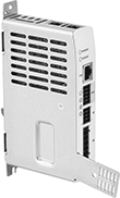
| 20 | EtherCAT, Modbus TCP/IP, EtherNet/IP, Profinet, TCP/IP | 24 to 48 | 5.2" | 1.1" | 6.7" | 2 | 2 | IP20 | 5203N201 | 0000000 | |||||||||||||||||||||||||||||||||||||||||||||||||||||||||||||||||||||||||||||||||||||||||
Low-Profile Electric Positioning Slides with Automated Controls
 |
Overall, mm | Carriage | ||||||||||||||||||||||||||||||||||||||||||||||||||||||||||||||||||||||||||||||||||||||||||||||||||
|---|---|---|---|---|---|---|---|---|---|---|---|---|---|---|---|---|---|---|---|---|---|---|---|---|---|---|---|---|---|---|---|---|---|---|---|---|---|---|---|---|---|---|---|---|---|---|---|---|---|---|---|---|---|---|---|---|---|---|---|---|---|---|---|---|---|---|---|---|---|---|---|---|---|---|---|---|---|---|---|---|---|---|---|---|---|---|---|---|---|---|---|---|---|---|---|---|---|---|---|
Dynamic Horiz. Load Cap., lb. | Max. Speed, mm/s | Travel Distance per Full Step, mm | Repeatability, μm | Lg. | Wd. | Ht. | Lg., mm | Wd., mm | Bearing Type | Base Material | Full Load Current, amp | Voltage, V DC | Operating System Compatibility | Each | |||||||||||||||||||||||||||||||||||||||||||||||||||||||||||||||||||||||||||||||||||||
25 mm Stroke Length | |||||||||||||||||||||||||||||||||||||||||||||||||||||||||||||||||||||||||||||||||||||||||||||||||||
| 11 | 1,300 | 0.0005 | -0.5 to 0.5 | 120 | 55 | 14 | 80 | 48 | Ball | Nickel-Plated Steel | 1.2 | 48 | Windows 10 or Later | 6468N13 | 000000000 | ||||||||||||||||||||||||||||||||||||||||||||||||||||||||||||||||||||||||||||||||||||
| 11 | 1,300 | 0.0005 | -0.5 to 0.5 | 120 | 80 | 16 | 80 | 68 | Ball | Nickel-Plated Steel | 1 | 48 | Windows 10 or Later | 6468N15 | 00000000 | ||||||||||||||||||||||||||||||||||||||||||||||||||||||||||||||||||||||||||||||||||||
65 mm Stroke Length | |||||||||||||||||||||||||||||||||||||||||||||||||||||||||||||||||||||||||||||||||||||||||||||||||||
| 11 | 1,300 | 0.0005 | -0.5 to 0.5 | 160 | 55 | 14 | 80 | 48 | Ball | Nickel-Plated Steel | 2.4 | 48 | Windows 10 or Later | 6468N14 | 00000000 | ||||||||||||||||||||||||||||||||||||||||||||||||||||||||||||||||||||||||||||||||||||
| 11 | 1,300 | 0.0005 | -0.5 to 0.5 | 160 | 80 | 16 | 80 | 68 | Ball | Nickel-Plated Steel | 2.1 | 48 | Windows 10 or Later | 6468N16 | 00000000 | ||||||||||||||||||||||||||||||||||||||||||||||||||||||||||||||||||||||||||||||||||||
120 mm Stroke Length | |||||||||||||||||||||||||||||||||||||||||||||||||||||||||||||||||||||||||||||||||||||||||||||||||||
| 11 | 1,300 | 0.0005 | -0.5 to 0.5 | 280 | 80 | 16 | 140 | 68 | Ball | Nickel-Plated Steel | 2.1 | 48 | Windows 10 or Later | 6468N17 | 00000000 | ||||||||||||||||||||||||||||||||||||||||||||||||||||||||||||||||||||||||||||||||||||
