


Filter by
Electrical Connection Type
System of Measurement
Maximum Pull
Voltage
Length
Wattage
Mount Type
Electrical Connection
Wire Connection
Height
Maximum Temperature
Threading
Sets of Poles
Mounting Hole Style
DFARS Specialty Metals
Export Control Classification Number (ECCN)

About Magnets
Choose a magnet with the right strength, material, and temperature resistance for your application.
Hardwire Electromagnets
Disc
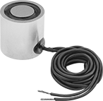 |
Spring-Loaded Release—Magnets with spring-loaded release have a pin that pops up to separate the object and magnet when the power is turned off.
Wattage, W | OD | Ht. | Max. Pull, lbf | Sets of Poles | Max. Temp., ° F | Thread Size | Thread Dp. | No. of Mounting Holes | Mounting Hole Ctr.-to-Ctr. | Wire Lead Lg. | Features | Each | |||
|---|---|---|---|---|---|---|---|---|---|---|---|---|---|---|---|
12V DC | |||||||||||||||
| 1.4 | 1/2" | 1 1/2" | 4 | 1 | 100 | 6-32 | 1/2" | 1 | — | 24" | — | 5698K7 | 0000000 | ||
| 1.4 | 3/4" | 1 1/4" | 9 | 1 | 100 | 10-32 | 3/8" | 1 | — | 24" | — | 5698K111 | 00000 | ||
| 1.4 | 1" | 3/4" | 26 | 1 | 100 | 10-32 | 3/8" | 1 | — | 24" | — | 5698K112 | 00000 | ||
| 3.6 | 1" | 1 1/4" | 32 | 1 | 100 | 10-32 | 1/2" | 1 | — | 24" | — | 5698K113 | 00000 | ||
| 4.4 | 1 1/4" | 1 1/4" | 50 | 1 | 100 | 1/4"-20 | 1/2" | 1 | — | 24" | — | 5698K114 | 00000 | ||
| 4.6 | 1 1/2" | 1 1/2" | 80 | 1 | 100 | 1/4"-20 | 1/2" | 1 | — | 24" | — | 5698K115 | 00000 | ||
| 5.6 | 2" | 1 5/8" | 180 | 1 | 100 | 1/4"-20 | 1/2" | 1 | — | 24" | — | 5698K116 | 00000 | ||
24V DC | |||||||||||||||
| 0.9 | 25/32" | 63/64" | 1 | 1 | 100 | M5 x 0.8 mm | 0.19" | 1 | — | 8" | Spring-Loaded Release | 5893K92 | 000000 | ||
| 1.4 | 1/2" | 1 1/2" | 4 | 1 | 100 | 6-32 | 3/8" | 1 | — | 24" | — | 5698K97 | 000000 | ||
| 1.4 | 3/4" | 1 1/4" | 9 | 1 | 100 | 10-32 | 3/8" | 1 | — | 24" | — | 5698K211 | 00000 | ||
| 1.4 | 1" | 3/4" | 26 | 1 | 100 | 10-32 | 3/8" | 1 | — | 24" | — | 5698K212 | 00000 | ||
| 2 | 1.18" | 63/64" | 6 | 1 | 100 | M6 x 1 mm | 0.23" | 1 | — | 8" | Spring-Loaded Release | 5893K94 | 000000 | ||
| 2.9 | 1.57" | 63/64" | 22 | 1 | 100 | M6 x 1 mm | 0.29" | 1 | — | 8" | Spring-Loaded Release | 5893K96 | 000000 | ||
| 3.6 | 1" | 1 1/4" | 32 | 1 | 100 | 10-32 | 1/2" | 1 | — | 24" | — | 5698K213 | 00000 | ||
| 4.4 | 1 1/4" | 1 1/4" | 50 | 1 | 100 | 1/4"-20 | 1/2" | 1 | — | 24" | — | 5698K214 | 00000 | ||
| 4.6 | 1 1/2" | 1 1/2" | 80 | 1 | 100 | 1/4"-20 | 1/2" | 1 | — | 24" | — | 5698K215 | 00000 | ||
| 5.6 | 2" | 1 5/8" | 180 | 1 | 100 | 1/4"-20 | 1/2" | 1 | — | 24" | — | 5698K216 | 000000 | ||
110V DC | |||||||||||||||
| 8 | 3 1/2" | 1 1/2" | 650 | 1 | 100 | 1/4"-20 | 1/2" | 2 | 1" | 24" | — | 5698K76 | 000000 | ||
| 33 | 4" | 3" | 1,000 | 1 | 100 | 3/8"-16 | 5/8" | 2 | 1" | 24" | — | 5698K77 | 000000 | ||
| 60 | 10" | 2 1/2" | 4,700 | 1 | 100 | 5/8"-11 | 2" | 2 | 3" | 72" | — | 5698K75 | 00000000 | ||
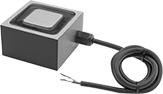
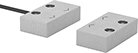
Rectangle
 |
Wattage, W | Wd. | Lg. | Ht. | Max. Pull, lbf | Sets of Poles | Max. Temp., ° F | Thread Size | Thread Dp. | No. of Mounting Holes | Mounting Hole Ctr.-to-Ctr. | Wire Lead Lg. | Each | |||
|---|---|---|---|---|---|---|---|---|---|---|---|---|---|---|---|
12V DC | |||||||||||||||
| 8 | 1 1/2" | 1 1/2" | 1 1/4" | 100 | 1 | 100 | 10-32 | 3/8" | 1 | — | 24" | 5698K311 | 0000000 | ||
| 10 | 1 1/2" | 2 1/2" | 1 1/4" | 160 | 1 | 100 | 10-32 | 3/8" | 2 | 1" | 24" | 5698K312 | 000000 | ||
| 14 | 2 1/2" | 2 1/2" | 1 1/2" | 300 | 1 | 100 | 1/4"-20 | 1/2" | 3 | 3/8" | 36" | 5698K313 | 000000 | ||
| 29 | 2 1/2" | 4 1/2" | 1 7/8" | 600 | 1 | 100 | 1/4"-20 | 3/4" | 2 | 2" | 36" | 5698K315 | 000000 | ||
24V DC | |||||||||||||||
| 8 | 1 1/2" | 1 1/2" | 1 1/4" | 100 | 1 | 100 | 10-32 | 3/8" | 1 | — | 24" | 5698K411 | 000000 | ||
| 10 | 1 1/2" | 2 1/2" | 1 1/4" | 160 | 1 | 100 | 10-32 | 3/8" | 2 | 1" | 24" | 5698K412 | 000000 | ||
| 14 | 2 1/2" | 2 1/2" | 1 1/2" | 300 | 1 | 100 | 1/4"-20 | 1/2" | 3 | 3/8" | 36" | 5698K413 | 000000 | ||
| 28 | 3 1/2" | 3 1/2" | 2" | 700 | 1 | 100 | 3/8"-16 | 3/4" | 1 | — | 36" | 5698K414 | 000000 | ||
| 29 | 2 1/2" | 4 1/2" | 1 7/8" | 600 | 1 | 100 | 1/4"-20 | 3/4" | 2 | 2" | 36" | 5698K415 | 000000 | ||
110V DC | |||||||||||||||
| 12 | 2 1/2" | 4 1/2" | 2" | 750 | 1 | 100 | 1/4"-20 | 1/2" | 2 | 2" | 24" | 5698K72 | 000000 | ||
| 37 | 3" | 6" | 2" | 1,000 | 1 | 100 | 3/8"-16 | 3/8" | 2 | 3" | 24" | 5698K71 | 000000 | ||
| 58 | 4" | 8" | 2 1/2" | 1,700 | 1 | 100 | 3/8"-16 | 1" | 2 | 4" | 36" | 5698K511 | 000000 | ||
| 65 | 6" | 12" | 3 1/2" | 5,000 | 1 | 100 | 1/2"-13 | 1 1/4" | 2 | 3" | 72" | 5698K74 | 00000000 | ||
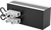
Hardwire Electromagnets with Parallel Poles
Rectangle
 |
Wattage, W | Wd. | Lg. | Ht. | Max. Pull, lbf | Sets of Poles | Max. Temp., ° F | Thread Size | Thread Dp. | No. of Mounting Holes | Mounting Hole Ctr.-to-Ctr. | Each | |||
|---|---|---|---|---|---|---|---|---|---|---|---|---|---|---|
24V DC | ||||||||||||||
| 5 | 1" | 2" | 1 3/8" | 80 | 1 | 100 | 1/4"-20 | 1/4" | 2 | 1" | 5684K16 | 0000000 | ||
| 7.8 | 1" | 3" | 1 3/8" | 170 | 1 | 100 | 1/4"-20 | 1/4" | 2 | 2" | 5684K17 | 000000 | ||
| 9.3 | 1" | 4" | 1 3/8" | 210 | 1 | 100 | 1/4"-20 | 1/4" | 2 | 3" | 5684K18 | 000000 | ||
| 18 | 1" | 6" | 1 3/8" | 260 | 1 | 100 | 1/4"-20 | 1/4" | 2 | 4 1/2" | 5684K19 | 000000 | ||
| 21 | 2" | 4" | 2 3/4" | 470 | 1 | 100 | 5/16"-18 | 1/4" | 2 | 3" | 5684K21 | 000000 | ||
| 30 | 2" | 6" | 2 3/4" | 620 | 1 | 100 | 5/16"-18 | 1/4" | 2 | 4 1/2" | 5684K22 | 000000 | ||
| 36 | 2" | 8" | 2 3/4" | 930 | 1 | 100 | 5/16"-18 | 1/4" | 2 | 6 1/2" | 5684K23 | 000000 | ||
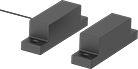
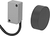
Magnetically Actuated Switches
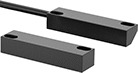 | 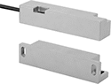 | 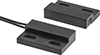 |
Style A | Style B | Style C |
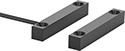 | ||
Style D | Style E | Style F |
 |  |  |
Style G | Style H | Style J |
 | ||
Style K | Style L |
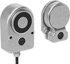
These switches actuate when a magnet comes within sensing distance, and reset when the magnet moves away. They’re often used to detect when a door or window opens. Mount the switch in a stationary position, such as a door frame, and mount the magnet to a movable object, such as the door. They do not include a safety relay and cannot be used with safety-guard doors found on machinery.
LED Status Indicator—Switches with an LED status indicator let you visually confirm that it’s connected and whether it’s actuated.
NEMA 4X Enclosure Rating—NEMA 4X rated switches are protected from corrosion and washdowns.
NEMA 6 Enclosure Rating—NEMA 6 rated switches are protected from temporary submersion.
IP67 Enclosure Rating—IP67 rated switches protect against temporary submersion, as well as dust and dirt.
IP69 Enclosure Rating—IP69 rated switches resist high temperature washdowns and dust.
Switches | Replacement Magnets | |||||||||||||||||||
|---|---|---|---|---|---|---|---|---|---|---|---|---|---|---|---|---|---|---|---|---|
Wire Leads | ||||||||||||||||||||
Style | No. of Circuits Controlled | Switch Starting Position | Switch Designation | Switching Current @ Voltage | Max. Voltage | Max. Sensing Distance | No. of | Lg., ft. | Dia. | Lg. | Wd. | Ht. | Mounting Thread Size | Enclosure Rating | Each | Each | ||||
Plastic Housing with Wire Leads | ||||||||||||||||||||
| A | 1 | 1 Off | SPST-NO | 1 amp @ 24V DC | 200V DC | 0.44" | 2 | 1/2 | — | 1.1" | 0.33" | 0.21" | — | — | 65985K311 | 000000 | 65985K344 | 000000 | ||
| A | 1 | 1 Off | SPST-NO | 2 amp @ 30V AC, 2 amp @ 60V DC | 250V AC 250V DC | 0.8" | 2 | 3 | — | 3.16" | 0.79" | 0.59" | — | NEMA 4X, IP67 | 65985K76 | 000000 | 65985K85 | 00000 | ||
| A | 1 | 1 On | SPST-NC | 1 amp @ 24V DC | 150V DC | 0.25" | 2 | 1/2 | — | 1.1" | 0.33" | 0.21" | — | — | 65985K313 | 00000 | 65985K344 | 00000 | ||
| A | 1 | 1 On | SPST-NC | 1 amp @ 24V DC | 150V DC | 0.31" | 2 | 1/2 | — | 1.1" | 0.33" | 0.21" | — | — | 65985K312 | 00000 | 65985K344 | 00000 | ||
| A | 1 | 1 On | SPST-NC | 2 amp @ 230V AC | 230V AC | 0.47" | 2 | 6 | — | 3" | 1.19" | 0.63" | — | NEMA 6, IP67 | 65985K426 | 000000 | 65985K441 | 000000 | ||
| B | 1 | 1 On | SPST-NC | 1 amp @ 30V DC | 30V DC | 0.47" | 2 | 10 | — | 3.25" | 0.75" | 0.67" | — | NEMA 6, IP67 | 65985K427 | 000000 | 65985K439 | 00000 | ||
| B | 1 | 1 On | SPST-NC | 2 amp @ 230V AC | 230V AC | 0.47" | 2 | 19 | — | 3.25" | 0.75" | 0.67" | — | NEMA 6, IP67 | 65985K421 | 000000 | 65985K439 | 00000 | ||
| B | 2 | 1 Off and 1 On | DPST-1NO/1NC | 1 amp @ 30V DC | 30V DC | 0.47" | 4 | 19 | — | 3.25" | 0.75" | 0.67" | — | NEMA 6, IP67 | 65985K419 | 000000 | 65985K439 | 00000 | ||
| B | 2 | 1 Off and 1 On | DPST-1NO/1NC | 2 amp @ 230V AC | 230V AC | 0.47" | 4 | 19 | — | 3.25" | 0.75" | 0.67" | — | NEMA 6, IP67 | 65985K434 | 000000 | 65985K439 | 00000 | ||
| B | 2 | 2 On | DPST-NC | 1 amp @ 30V DC | 30V DC | 0.47" | 4 | 19 | — | 3.25" | 0.75" | 0.67" | — | NEMA 6, IP67 | 65985K425 | 000000 | 65985K439 | 00000 | ||
| B | 2 | 2 On | DPST-NC | 2 amp @ 230V AC | 230V AC | 0.47" | 4 | 19 | — | 3.25" | 0.75" | 0.67" | — | NEMA 6, IP67 | 65985K429 | 000000 | 65985K439 | 00000 | ||
| C | 1 | 1 Off | SPST-NO | 1 amp @ 24V DC | 200V DC | 0.31" | 2 | 1/2 | — | 1.125" | 0.75" | 0.25" | — | — | 65985K321 | 00000 | 65985K339 | 00000 | ||
| C | 1 | 1 Off | SPST-NO | 2 amp @ 24V DC | 400V DC | 0.25" | 2 | 1/2 | — | 1.13" | 0.75" | 0.25" | — | — | 65985K11 | 00000 | 65985K339 | 00000 | ||
| C | 1 | 1 Off | SPST-NO | 80 mA @ 120V AC | 250V AC | 0.4" | 2 | 3 | — | 1.13" | 0.71" | 0.25" | — | NEMA 4X, IP67 | 65985K72 | 000000 | 65985K82 | 00000 | ||
| C | 1 | 1 Off or 1 On | SPDT | 1 amp @ 24V DC | 150V DC | 0.2" | 3 | 1/2 | — | 1.13" | 0.75" | 0.25" | — | — | 65985K12 | 00000 | 65985K339 | 00000 | ||
| C | 1 | 1 Off or 1 On | SPDT | 1 amp @ 24V DC | 150V DC | 0.44" | 3 | 1/2 | — | 1.125" | 0.75" | 0.25" | — | — | 65985K322 | 00000 | 65985K339 | 00000 | ||
| D | 1 | 1 Off | SPST-NO | 1 amp @ 24V DC | 200V DC | 0.25" | 2 | 1/2 | 0.31" | 1.5" | — | — | 5/16"-24 | — | 65985K323 | 00000 | 65985K347 | 00000 | ||
| D | 1 | 1 Off | SPST-NO | 2 amp @ 24V DC | 400V DC | 0.2" | 2 | 1/2 | 0.31" | 1.5" | — | — | 5/16"-24 | — | 65985K13 | 00000 | 65985K347 | 00000 | ||
| D | 1 | 1 Off or 1 On | SPDT | 1 amp @ 24V DC | 150V DC | 0.13" | 3 | 1/2 | 0.31" | 1.5" | — | — | 5/16"-24 | — | 65985K14 | 00000 | 65985K347 | 00000 | ||
| D | 1 | 1 Off or 1 On | SPDT | 1 amp @ 24V DC | 150V DC | 0.31" | 3 | 1/2 | 0.31" | 1.5" | — | — | 5/16"-24 | — | 65985K324 | 00000 | 65985K347 | 00000 | ||
| E | 1 | 1 Off | SPST-NO | 0.4 amp @ 24V DC | 170V DC | 0.15" | 2 | 1/2 | 0.18" | 0.43" | — | — | — | — | 65985K15 | 00000 | 65985K345 | 00000 | ||
| E | 1 | 1 Off | SPST-NO | 1 amp @ 24V DC | 200V DC | 0.31" | 2 | 1/2 | 0.25" | 1" | — | — | — | — | 65985K325 | 00000 | 65985K346 | 00000 | ||
| E | 1 | 1 Off | SPST-NO | 80 mA @ 120V AC | 250V AC | 0.1" | 2 | 3 | 0.24" | 1.12" | — | — | — | NEMA 4X, IP67 | 65985K71 | 000000 | 65985K81 | 00000 | ||
| E | 1 | 1 Off or 1 On | SPDT | 1 amp @ 24V DC | 150V DC | 0.19" | 3 | 1/2 | 0.25" | 1" | — | — | — | — | 65985K327 | 00000 | 65985K346 | 00000 | ||
| F | 1 | 1 Off | SPST-NO | 1 amp @ 24V DC | 200V DC | 0.56" | 2 | 1/2 | — | 1.75" | 0.25" | 0.26" | — | — | 65985K314 | 00000 | 65985K341 | 00000 | ||
| F | 1 | 1 Off | SPST-NO | 2 amp @ 24V DC | 400V DC | 0.62" | 2 | 1/2 | — | 1.75" | 0.25" | 0.26" | — | — | 65985K315 | 00000 | 65985K341 | 00000 | ||
| F | 1 | 1 Off | SPST-NO | 3 amp @ 24V DC | 400V DC | 0.94" | 2 | 1/2 | — | 2.625" | 0.34" | 0.34" | — | — | 65985K318 | 00000 | 65985K342 | 00000 | ||
| F | 1 | 1 Off or 1 On | SPDT | 1 amp @ 24V DC | 150V DC | 0.62" | 3 | 1/2 | — | 1.75" | 0.25" | 0.26" | — | — | 65985K317 | 00000 | 65985K341 | 00000 | ||
| F | 1 | 1 Off or 1 On | SPDT | 3 amp @ 24V DC | 120V DC | 0.81" | 3 | 1/2 | — | 2.625" | 0.34" | 0.34" | — | — | 65985K319 | 00000 | 65985K342 | 00000 | ||
| G | 1 | 1 Off | SPST-NO | 2 amp @ 24V DC | 400V DC | 0.94" | 2 | 1 1/2 | — | 2.53" | 0.625" | 0.75" | — | — | 65985K329 | 00000 | 65985K343 | 00000 | ||
| G | 1 | 1 Off | SPST-NO | 3 amp @ 24V DC | 400V DC | 0.94" | 2 | 1 1/2 | — | 2.53" | 0.625" | 0.75" | — | — | 65985K328 | 00000 | 65985K343 | 00000 | ||
| H | 3 | 1 Off and 2 On | 3PST-1NO/2NC | 0.3 amp @ 30V DC | 30V DC | 0.47" | 6 | 16 | — | 2.08" | 1.1" | 0.55" | — | NEMA 6, IP67 | 65985K423 | 000000 | 65985K438 | 00000 | ||
Plastic Housing with Wire Leads and LED Status Indicator | ||||||||||||||||||||
| J | 1 | 1 Off | SPST-NO | 0.2 amp @ 3V DC | 30V DC | 2.36" | 3 | 6 | — | 1.09" | 0.63" | 0.4" | — | IP67 | 65985K502 | 000000 | 65985K408 | 00000 | ||
Stainless Steel Housing with Wire Leads | ||||||||||||||||||||
| A | 3 | 1 Off and 2 On | 3PST-1NO/2NC | 1 amp @ 30V DC | 30V DC | 0.47" | 6 | 10 | — | 3.11" | 1.3" | 0.63" | — | NEMA 6, IP67 | 65985K432 | 000000 | 65985K435 | 000000 | ||
| B | 1 | 1 On | SPST-NC | 2 amp @ 230V AC | 230V AC | 0.47" | 2 | 10 | — | 3.21" | 0.75" | 0.75" | — | NEMA 6, IP67 | 65985K418 | 000000 | 65985K437 | 000000 | ||
| B | 2 | 1 Off and 1 On | DPST-1NO/1NC | 1 amp @ 30V DC | 30V DC | 0.47" | 4 | 10 | — | 3.21" | 0.75" | 0.75" | — | NEMA 6, IP67 | 65985K431 | 000000 | 65985K437 | 000000 | ||
| B | 3 | 1 Off and 2 On | 3PST-1NO/2NC | 1 amp @ 30V DC | 30V DC | 0.47" | 6 | 10 | — | 3.21" | 0.75" | 0.75" | — | NEMA 6, IP67 | 65985K428 | 000000 | 65985K437 | 000000 | ||
| D | 1 | 1 Off | SPST-NO | 1 amp @ 24V DC | 200V DC | 0.38" | 2 | 1/2 | 0.31" | 1.25" | — | — | 5/16"-24 | — | 65985K331 | 00000 | 65985K351 | 00000 | ||
| D | 1 | 1 Off | SPST-NO | 2 amp @ 120V AC, 2 amp @ 24V DC | 400V AC 400V DC | 0.13" | 2 | 1/2 | 0.31" | 1.25" | — | — | 5/16"-24 | — | 65985K21 | 00000 | 65985K351 | 00000 | ||
| D | 1 | 1 Off or 1 On | SPDT | 0.8 amp @ 24V DC | 150V DC | 0.2" | 3 | 1/2 | 0.31" | 1.25" | — | — | 5/16"-24 | — | 65985K22 | 00000 | 65985K351 | 00000 | ||
| D | 1 | 1 Off or 1 On | SPDT | 1 amp @ 24V DC | 150V DC | 0.44" | 3 | 1/2 | 0.31" | 1.25" | — | — | 5/16"-24 | — | 65985K332 | 00000 | 65985K351 | 00000 | ||
| H | 3 | 1 Off and 2 On | 3PST-1NO/2NC | 0.3 amp @ 30V DC | 30V DC | 0.47" | 6 | 16 | — | 2.08" | 1.14" | 0.53" | — | NEMA 6, IP67 | 65985K433 | 000000 | 65985K436 | 000000 | ||
Stainless Steel Housing with Wire Leads and LED Status Indicator | ||||||||||||||||||||
| K | 1 | 1 Off | SPST-NO | 0.2 amp @ 3V DC | 30V DC | 2.36" | 3 | 6 | 0.31" | 1.96" | — | — | M8 × 1 mm | IP67 | 65985K513 | 000000 | 65985K408 | 00000 | ||
| K | 1 | 1 Off | SPST-NO | 0.2 amp @ 3V DC | 30V DC | 2.36" | 3 | 6 | 0.47" | 1.96" | — | — | M12 × 1 mm | IP67 | 65985K515 | 000000 | 65985K408 | 00000 | ||
| K | 1 | 1 Off | SPST-NO | 0.2 amp @ 3V DC | 30V DC | 2.75" | 3 | 6 | 0.71" | 1.96" | — | — | M18 × 1 mm | IP67 | 65985K514 | 000000 | 65985K408 | 00000 | ||
| L | 3 | 1 Off and 2 On | 3PST-1NO/2NC | 10 mA @ 24V DC | 24V DC | 0.31" | 6 | 10 | — | 3.46" | 1.06" | 0.55" | — | IP69 | 65985K511 | 000000 | 65985K415 | 00000 | ||
Aluminum Housing with Wire Leads | ||||||||||||||||||||
| D | 1 | 1 Off | SPST-NO | 1 amp @ 24V DC | 200V DC | 0.56" | 2 | 1/2 | 0.31" | 1.5" | — | — | 5/16"-24 | — | 65985K333 | 00000 | 65985K348 | 00000 | ||
| D | 1 | 1 Off | SPST-NO | 2 amp @ 24V DC | 400V DC | 0.31" | 2 | 1/2 | 0.31" | 1.5" | — | — | 5/16"-24 | — | 65985K334 | 00000 | 65985K348 | 00000 | ||
| D | 1 | 1 Off | SPST-NO | 2.5 amp @ 24V DC | 400V DC | 0.19" | 2 | 1/2 | 0.31" | 1.25" | — | — | 5/16"-24 | — | 65985K23 | 00000 | 65985K352 | 00000 | ||
| D | 1 | 1 Off | SPST-NO | 3 amp @ 24V DC | 400V DC | 0.56" | 2 | 1 1/2 | 0.38" | 2.125" | — | — | 3/8"-27 | — | 65985K337 | 00000 | 65985K349 | 00000 | ||
| D | 1 | 1 Off or 1 On | SPDT | 1 amp @ 24V DC | 150V DC | 0.19" | 3 | 1/2 | 0.31" | 1.5" | — | — | 5/16"-24 | — | 65985K336 | 00000 | 65985K348 | 00000 | ||
| D | 1 | 1 Off or 1 On | SPDT | 1 amp @ 24V DC | 150V DC | 0.31" | 3 | 1/2 | 0.31" | 1.5" | — | — | 5/16"-24 | — | 65985K335 | 00000 | 65985K348 | 00000 | ||
| D | 1 | 1 Off or 1 On | SPDT | 3 amp @ 24V DC | 120V DC | 0.44" | 3 | 1/2 | 0.38" | 2.125" | — | — | 3/8"-27 | — | 65985K338 | 000000 | 65985K349 | 00000 | ||
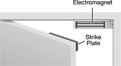
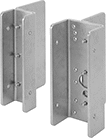
Electromagnetic Door Locks
 |
Flush Mount |
 |
Offset Mount |
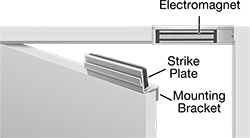
For use alone or as part of an access-control system, these locks use electromagnetic force to hold single doors closed. Control the locks with a push-button switch or keypad door control (sold separately). When power is interrupted, they instantly release. All locks must be hardwired.
Delayed—Those with delayed locking speed lock doors after a set amount of time.
Instant—Locks with instant locking speed lock doors as soon as they are closed.
Flush Mount—Flush mount locks mount under the door frame header. For locks with 500 lbs. and 1,500 lbs. of holding strength, a 5/8" thick filler plate (sold separately) is required if the mounting surface on the frame is less than 2" wide.
Offset Mount—Offset mount locks mount on the door frame header and include a mounting bracket that extends the strike plate above the door.
Backup Battery Packs—Battery backup packs supply power during power interruptions.
Locks | Backup Battery Packs | Door Filler Plates | |||||||||||||||||||
|---|---|---|---|---|---|---|---|---|---|---|---|---|---|---|---|---|---|---|---|---|---|
Electromagnet | Strike Plate | Flush Mount | Offset Mount | ||||||||||||||||||
Locking Speed | Delayed Locking Time Range, sec. | Holding Strength, lbf | Voltage Range, V DC | Ht. | Wd. | Dp. | Ht. | Wd. | Dp. | Mounting Hardware Included | Electrical Connection Type | Each | Each | Each | Each | ||||||
RCI 8375 | |||||||||||||||||||||
| Instant | — | 300 | 12 to 24 | 1 1/2" | 6 9/16" | 13/16" | 1 1/4" | 5 1/8" | 3/8" | Yes | Hardwire | 10455A64 | 0000000 | 10455A74 | 0000000 | 1251A11 | 0000000 | ——— | 0 | ||
Schlage M420 | |||||||||||||||||||||
| Instant | — | 500 | 12 to 24 | 2 1/2" | 9" | 1 1/2" | 1 3/4" | 5 5/16" | 5/8" | Yes | Hardwire | 10455A76 | 000000 | 10455A85 | 000000 | 1251A11 | 000000 | 1251A14 | 000000 | ||
Schlage M490P | |||||||||||||||||||||
| Delayed | 0.5 to 30 | 1,500 | 12 to 24 | 3" | 12 1/2" | 1 3/4" | 2 1/4" | 8 3/4" | 1/2" | Yes | Hardwire | 1251A54 | 000000 | 1251A94 | 000000 | 1251A11 | 000000 | 1251A14 | 00000 | ||
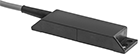
Frame-Mounted RFID Safety Switches
 |  |
Switch Shown Installed with LED Status Indicator | Stainless Steel Housing |
Prevent accidental bumps or vibration from triggering these safety switches unnecessarily—a strong magnet maintains the RFID signal between the actuator and switch until it's intentionally opened. Also known as interlock switches, they automatically cut power when you open an access door, interrupting the signal, then restore power when the door is closed, and the switch and actuator meet. They're designed to mount on a frame and a door, gate, or window. Use them in many ways—from turning off a machine-operated saw when you open the protective window to powering down robotic arms when someone enters the partitioned area. The LED indicator shows that your switch is on and whether it’s actuated.
For the Manufacturer User Manual, click on a part number and select Product Detail.
Unique RFID Code—Switches with a unique RFID code are only compatible with their own actuator, so they’re difficult to tamper with.
IP69K Enclosure Rating—IP69K rated switches protect against high-pressure, high-temperature washdowns.
Number of Safety Outputs—The number of safety outputs, also known as output signal switching devices (OSSDs), tells you how many machines you can control. Each output has a pair of signals that shut down a single machine—if one signal fails, the other takes over as a failsafe.
Housing | |||||||||||||||||
|---|---|---|---|---|---|---|---|---|---|---|---|---|---|---|---|---|---|
No. of Safety Outputs | Holding Force, lbf | Max. Sensing Distance, mm | Input Voltage, V DC | Current Output, mA | Output Digital Signal | No. of Wire Leads | Cable Lead Lg., ft. | Ht. | Wd. | Dp. | Mounting Fasteners Included | Features | Enclosure Rating | Each | |||
Stainless Steel Housing | |||||||||||||||||
Wire Lead Connection | |||||||||||||||||
| 1 | 101 | 10 | 24 | 200 | PNP | 8 | 16 | 3.8" | 2.5" | 1.5" | Yes | Auxiliary PNP Output, LED Status Indicator, Magnetic Latch, Unique RFID Code | IP69K | 8043N11 | 0000000 | ||
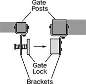
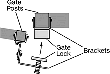
Electromagnetic Gate Locks
 |
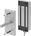 | 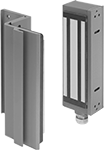 |
Assa Abloy Securitron | Schlage |
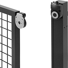
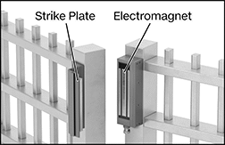
For use alone or as part of an access-control system, these locks use electromagnets to hold gates closed. Remotely control these locks with a push-button switch or keypad control (sold separately). They lock automatically as soon as the gate is closed. When power is interrupted, these locks instantly release. The electromagnets include wire leads for easy electrical connection.
Assa Abloy Securitron—Assa Abloy Securitron locks are configurable to either 12V DC or 24V DC. They have a shock-absorbing strike plate that cushions the electromagnet, so the gate and lock won’t be damaged from impact as the gate door closes.
Schlage—Schlage locks are dual voltage rated for both 12V DC and 24V DC. They don’t require configuration.
Backup Battery Packs—Backup battery packs supply power for Schlage locks during power interruptions.
Door Filler Plates—Filler plates are required for Schlage locks if the mounting surface is less than 2" wide.
Locks | Backup Battery Packs | Door Filler Plates | ||||||||||||||||
|---|---|---|---|---|---|---|---|---|---|---|---|---|---|---|---|---|---|---|
Electromagnet | Strike Plate | Surface Mount | ||||||||||||||||
Locking Speed | Holding Strength, lbf | Voltage Range, V DC | Ht. | Wd. | Dp. | Ht. | Wd. | Dp. | Mounting Fasteners Included | Electrical Connection Type | Each | Each | Each | |||||
Assa Abloy Securitron M62FG-SASM | ||||||||||||||||||
| Instant | 1,200 | 12 to 24 | 8" | 3" | 1 3/4" | 6" | 2 3/4" | 1/2" | Yes | Hardwire | 13585A11 | 0000000 | ——— | 0 | ——— | 0 | ||
Schlage M490G | ||||||||||||||||||
| Instant | 1,500 | 12 to 24 | 11" | 3" | 1 3/4" | 10 1/2" | 2 5/8" | 1" | Yes | Hardwire | 13585A49 | 000000 | 1251A11 | 0000000 | 1251A14 | 000000 | ||
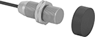
Tamper-Resistant Magnetically Actuated Switches
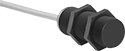 |  | 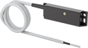 |
Style A with Wire Leads | Style B with Wire Leads | Style B with Wire Leads and LED Status Indicator |
 |  | |
Coded Magnet for Style A | Coded Magnet for Style B |
Prevent unauthorized use—these switches require coded magnets (sold separately) to actuate, and cannot be bypassed using ordinary magnets. They actuate when a magnet comes within sensing distance, and reset when the magnet moves away. Mount the switch in a stationary position, such as a door frame, and mount the magnet to a movable object, such as the door. They’re often used to detect when a door or window opens, and can be used with movable machine guards. All are rated IP67 for protection from temporary submersion.
Safety relays are required in safety applications with switches that control two or three circuits.
LED Status Indicator—Switches with an LED status indicator light up when they’re actuated, so you can see if they’re wired correctly with a quick glance.
Switches | Coded Magnets | |||||||||||||||||||
|---|---|---|---|---|---|---|---|---|---|---|---|---|---|---|---|---|---|---|---|---|
Style | No. of Circuits Controlled | Switch Starting Position | Switch Designation | Switching Current @ Voltage | Max. Voltage | Input Voltage | Max. Sensing Distance | Dia. | Lg. | Wd. | Ht. | Mounting Thread Size | Enclosure Rating | Each | Mounting Hole Dia. | Each | ||||
Plastic Housing with Wire Leads | ||||||||||||||||||||
| A | 1 | 1 On | SPST-NC | 6.3 amp @ 120V AC | 250V AC | 24V DC | 0.2" | 1.2" | 3.1" | — | — | M30 × 1.5 mm | IP67 | 7225K11 | 0000000 | 0.18" | 7225K12 | 000000 | ||
| A | 2 | 1 Off and 1 On | DPST-1NO/1NC | 0.28 amp @ 120V AC, 0.4 amp @ 170V DC | 120V AC 170V DC | 120V AC 170V DC | 0.2" | 1.2" | 1.3" | — | — | M30 × 1.5 mm | IP67 | 7225K21 | 00000 | 0.18" | 7225K22 | 00000 | ||
| B | 2 | 1 Off and 1 On | DPST-1NO/1NC | 0.5 amp @ 120V AC/120V DC | 120V AC 120V DC | 120V AC 120V DC | 0.2" | — | 3.5" | 1" | 0.5" | — | IP67 | 7202K12 | 000000 | 0.2" | 7202K21 | 00000 | ||
| B | 3 | 1 Off and 2 On | 3PST-1NO/2NC | 10 mA @ 24V DC | 24V DC | 24V DC | 0.2" | — | 3.5" | 1" | 0.5" | — | IP67 | 7202K11 | 000000 | 0.2" | 7202K21 | 00000 | ||
| B | 3 | 1 Off and 2 On | 3PST-1NO/2NC | 0.4 amp @ 100V AC/100V DC | 100V AC 100V DC | 100V AC 100V DC | 0.2" | — | 3.5" | 1" | 0.5" | — | IP67 | 7202K33 | 000000 | 0.2" | 7202K21 | 00000 | ||
Plastic Housing with Wire Leads and LED Status Indicator | ||||||||||||||||||||
| B | 2 | 1 Off and 1 On | DPST-1NO/1NC | 10 mA @ 24V DC | 24V DC | 24V DC | 0.2" | — | 3.5" | 1" | 0.5" | — | IP67 | 7202K34 | 000000 | 0.2" | 7202K21 | 00000 | ||
Electromagnetic Locks for Double Doors
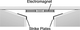 |
For use alone or as part of an access-control system, these locks use electromagnetic force to hold double doors closed. Control the locks with a push-button switch or keypad door control (sold separately). When power is interrupted, they instantly release. The locks must be hardwired.
Locks include two strike plates to control two doors at once. They mount under the door frame header and lock the instant doors are closed.
Backup Battery Packs—Battery backup packs supply power during power interruptions.
Door Filler Plates—A 5/8" thick filler plate (sold separately) is required if the mounting surface on the frame is less than 2" wide.
Locks | Backup Battery Packs | Door Filler Plates | ||||||||||||||||
|---|---|---|---|---|---|---|---|---|---|---|---|---|---|---|---|---|---|---|
Electromagnet | Strike Plate | Flush Mount | ||||||||||||||||
Locking Speed | Holding Strength, lbf | Voltage Range, V DC | Ht. | Wd. | Dp. | Ht. | Lg. | Dp. | Mounting Hardware Included | Electrical Connection Type | Each | Each | Each | |||||
Schlage M492 | ||||||||||||||||||
| Instant | 1,500 | 12 to 24 | 3" | 25 1/16" | 1 3/4" | 2 1/4" | 8 3/4" | 1/2" | Yes | Hardwire | 1251A96 | 000000000 | 1251A11 | 0000000 | 1251A14 | 000000 | ||
