


Filter by
Electrical Connector Component

Military Specification
System of Measurement
Electrical Connection
Housing Connection Method
Housing Finish
Housing Material
Maximum Temperature
Environment
Minimum Temperature
DFARS Specialty Metals
Export Control Classification Number (ECCN)
Mil. Spec. Push-In Connectors
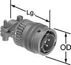
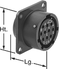
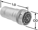
Solder Plugs—External Housing Lock
 |
3 Poles |
10 Poles |
No. of Poles | Voltage | Current, amp | For Wire Ga. | For Cable OD | Lg. | Wd. | Ht. | Housing Material | Temp. Range, ° F | Connector Shell Size | Mil. Spec. | Each | ||
|---|---|---|---|---|---|---|---|---|---|---|---|---|---|---|
| 3 | 1,000V AC/1,275V DC | 13 | 20, 19, 18, 17, 16 | 0.31" to 0.43" | 1.9" | 1" | 1" | Cadmium-Plated Aluminum | -65 to 255 | 12 | MIL-DTL-26482, MS3111F12-3P | 6134T61 | 000000 | |
| 10 | 600V AC/850V DC | 7.5 | 24, 23, 22, 21, 20 | 0.31" to 0.43" | 1.9" | 1" | 1" | Cadmium-Plated Aluminum | -65 to 255 | 12 | MIL-DTL-26482, MS3111F12-10P | 6134T64 | 00000 |
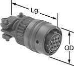
Solder Plugs—Internal Housing Lock
 |
3 Poles |
10 Poles |
No. of Poles | Voltage | Current, amp | For Wire Ga. | For Cable OD | OD | Lg. | Housing Material | Temp. Range, ° F | Connector Shell Size | Mil. Spec. | Each | ||
|---|---|---|---|---|---|---|---|---|---|---|---|---|---|
| 3 | 1,000V AC/1,275V DC | 13 | 20, 19, 18, 17, 16 | 0.31" to 0.43" | 1" | 1.9" | Cadmium-Plated Aluminum | -65 to 255 | 12 | MIL-DTL-26482, MS3116F12-3P | 6134T41 | 000000 | |
| 10 | 600V AC/850V DC | 7.5 | 24, 23, 22, 21, 20 | 0.31" to 0.43" | 1" | 1.9" | Cadmium-Plated Aluminum | -65 to 255 | 12 | MIL-DTL-26482, MS3116F12-10P | 6134T44 | 00000 |
Solder Sockets—External Housing Lock
 |
3 Poles |
10 Poles |
No. of Poles | Voltage | Current, amp | For Wire Ga. | For Cable OD | Lg. | Wd. | Ht. | Housing Material | Temp. Range, ° F | Connector Shell Size | Mil. Spec. | Each | ||
|---|---|---|---|---|---|---|---|---|---|---|---|---|---|---|
| 3 | 1,000V AC/1,275V DC | 13 | 20, 19, 18, 17, 16 | 0.31" to 0.43" | 1.9" | 1" | 1" | Cadmium-Plated Aluminum | -65 to 255 | 12 | MIL-DTL-26482, MS3111F12-3S | 6134T71 | 000000 | |
| 10 | 600V AC/850V DC | 7.5 | 24, 23, 22, 21, 20 | 0.31" to 0.43" | 1.9" | 1" | 1" | Cadmium-Plated Aluminum | -65 to 255 | 12 | MIL-DTL-26482, MS3111F12-10S | 6134T74 | 00000 |
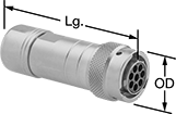
Solder Sockets—Internal Housing Lock
 |
3 Poles |
10 Poles |
No. of Poles | Voltage | Current, amp | For Wire Ga. | For Cable OD | OD | Lg. | Housing Material | Temp. Range, ° F | Connector Shell Size | Mil. Spec. | Each | ||
|---|---|---|---|---|---|---|---|---|---|---|---|---|---|
| 3 | 1,000V AC/1,275V DC | 13 | 20, 19, 18, 17, 16 | 0.31" to 0.43" | 1" | 1.9" | Cadmium-Plated Aluminum | -65 to 255 | 12 | MIL-DTL-26482, MS3116F12-3S | 6134T51 | 000000 | |
| 10 | 600V AC/850V DC | 7.5 | 24, 23, 22, 21, 20 | 0.31" to 0.43" | 1" | 1.9" | Cadmium-Plated Aluminum | -65 to 255 | 12 | MIL-DTL-26482, MS3116F12-10S | 6134T54 | 00000 |
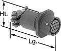
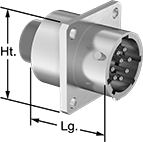
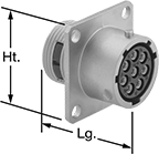
Male Panel-Mount Solder Receptacles—External Housing Lock
 |
3 Poles |
10 Poles |
No. of Poles | Voltage | Current, amp | For Wire Ga. | Lg. | Wd. | Ht. | Housing Material | For Panel Cutout Dia. | Temp. Range, ° F | Connector Shell Size | Mil. Spec. | Each | ||
|---|---|---|---|---|---|---|---|---|---|---|---|---|---|---|
| 3 | 1,000V AC/1,275V DC | 13 | 20, 19, 18, 17, 16 | 0.8" | 1" | 1" | Cadmium-Plated Aluminum | 0.7" | -65 to 255 | 12 | MIL-DTL-26482, MS3112E12-3P | 6134T21 | 000000 | |
| 10 | 600V AC/850V DC | 7.5 | 24, 23, 22, 21, 20 | 0.8" | 1" | 1" | Cadmium-Plated Aluminum | 0.7" | -65 to 255 | 12 | MIL-DTL-26482, MS3112E12-10P | 6134T24 | 00000 |
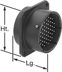
Female Panel-Mount Solder Receptacles—External Housing Lock
 |
3 Poles |
10 Poles |
No. of Poles | Voltage | Current, amp | For Wire Ga. | Lg. | Wd. | Ht. | Housing Material | For Panel Cutout Dia. | Temp. Range, ° F | Connector Shell Size | Mil. Spec. | Each | ||
|---|---|---|---|---|---|---|---|---|---|---|---|---|---|---|
| 3 | 1,000V AC/1,275V DC | 13 | 20, 19, 18, 17, 16 | 0.8" | 1" | 1" | Cadmium-Plated Aluminum | 0.86" | -65 to 255 | 12 | MIL-DTL-26482, MS3112E12-3S | 6134T31 | 000000 | |
| 10 | 600V AC/850V DC | 7.5 | 24, 23, 22, 21, 20 | 0.8" | 1" | 1" | Cadmium-Plated Aluminum | 0.86" | -65 to 255 | 12 | MIL-DTL-26482, MS3112E12-10S | 6134T34 | 00000 |
Mil. Spec. Compatible Connectors
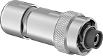
Crimp-On Plugs—Internal Housing Lock
 |  |  |  |
3 Poles (Clockwise) | 8 Poles (Clockwise) | 10 Poles (Clockwise) |
Mil. Spec. Plugs | Crimpers | ||||||||||||||
|---|---|---|---|---|---|---|---|---|---|---|---|---|---|---|---|
No. of Poles | Pole Layout | Voltage | Current, amp | For Wire Ga. | For Cable OD | OD | Lg. | Housing Material | Temp. Range, ° F | Connector Shell Size | Each | Each | |||
| 3 | Clockwise | 250V AC/500V AC/250V DC/500V DC | 13 | 26, 25, 24, 23, 22, 21, 20, 19, 18 | 0.26" to 0.39" | 1" | 2.9" | Nickel-Plated Zinc Alloy | -40 to 220 | 12 | 6168T17 | 000000 | 6168T3 | 000000000 | |
| 8 | Clockwise | 250V AC/500V AC/250V DC/500V DC | 13 | 26, 25, 24, 23, 22, 21, 20, 19, 18 | 0.26" to 0.39" | 1" | 2.9" | Nickel-Plated Zinc Alloy | -40 to 220 | 12 | 6168T18 | 00000 | 6168T3 | 00000000 | |
| 10 | Clockwise | 250V AC/250V DC | 7.5 | 30, 29, 28, 27, 26, 25, 24, 23, 22, 21, 20 | 0.24" to 0.39" | 1" | 2.9" | Nickel-Plated Zinc Alloy | -40 to 220 | 12 | 6168T12 | 00000 | 6168T3 | 00000000 | |
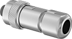
Crimp-On Sockets—Internal Housing Lock
 |  |  |  |
3 Poles (Counterclockwise) | 8 Poles (Counterclockwise) | 10 Poles (Counterclockwise) |
Mil. Spec. Sockets | Crimpers | ||||||||||||||
|---|---|---|---|---|---|---|---|---|---|---|---|---|---|---|---|
No. of Poles | Pole Layout | Voltage | Current, amp | For Wire Ga. | For Cable OD | OD | Lg. | Housing Material | Temp. Range, ° F | Connector Shell Size | Each | Each | |||
| 3 | Counterclockwise | 250V AC/500V AC/250V DC/500V DC | 13 | 26, 25, 24, 23, 22, 21, 20, 19, 18, 17, 16, 15, 14 | 0.26" to 0.39" | 1" | 2.9" | Nickel-Plated Zinc Alloy | -40 to 220 | 12 | 6168T37 | 000000 | 6168T3 | 000000000 | |
| 8 | Counterclockwise | 250V AC/500V AC/250V DC/500V DC | 13 | 26, 25, 24, 23, 22, 21, 20, 19, 18 | 0.26" to 0.39" | 1" | 2.9" | Nickel-Plated Zinc Alloy | -40 to 220 | 12 | 6168T38 | 00000 | 6168T3 | 00000000 | |
| 10 | Counterclockwise | 250V AC/250V DC | 7.5 | 30, 29, 28, 27, 26, 25, 24, 23, 22, 21, 20 | 0.24" to 0.39" | 1" | 2.9" | Nickel-Plated Zinc Alloy | -40 to 220 | 12 | 6168T32 | 00000 | 6168T3 | 00000000 | |
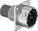
Male Panel-Mount Crimp-On Receptacles—External Housing Lock
 |
| |
3 Poles (Clockwise) | 8 Poles (Clockwise) |
| |
10 Poles (Clockwise) |
Crimpers—Crimpers are required for wire installation.
Mil. Spec. Receptacles | Crimpers | |||||||||||||||
|---|---|---|---|---|---|---|---|---|---|---|---|---|---|---|---|---|
No. of Poles | Pole Layout | Voltage | Current, amp | For Wire Ga. | Lg. | Wd. | Ht. | Housing Material | For Panel Cutout Dia. | Temp. Range, ° F | Connector Shell Size | Each | Each | |||
| 3 | Clockwise | 250V AC/500V AC/250V DC/500V DC | 13 | 26, 25, 24, 23, 22, 21, 20, 19, 18 | 1.3" | 1" | 1" | Nickel-Plated Zinc Alloy | 0.81" | -40 to 220 | 12 | 6168T57 | 000000 | 6168T3 | 000000000 | |
| 8 | Clockwise | 250V AC/500V AC/250V DC/500V DC | 13 | 26, 25, 24, 23, 22, 21, 20, 19, 18 | 1.3" | 1" | 1" | Nickel-Plated Zinc Alloy | 0.81" | -40 to 220 | 12 | 6168T58 | 00000 | 6168T3 | 00000000 | |
| 10 | Clockwise | 250V AC/250V DC | 7.5 | 30, 29, 28, 27, 26, 25, 24, 23, 22, 21, 20 | 1.3" | 1" | 1" | Nickel-Plated Zinc Alloy | 0.81" | -40 to 220 | 12 | 6168T52 | 00000 | 6168T3 | 00000000 | |
Female Panel-Mount Crimp-On Receptacles—External Housing Lock
 | | | |
3 Poles (Counterclockwise) | 8 Poles (Counterclockwise) | 10 Poles (Counterclockwise) |
Mil. Spec. Receptacles | Crimpers | |||||||||||||||
|---|---|---|---|---|---|---|---|---|---|---|---|---|---|---|---|---|
No. of Poles | Pole Layout | Voltage | Current, amp | For Wire Ga. | Lg. | Wd. | Ht. | Housing Material | For Panel Cutout Dia. | Temp. Range, ° F | Connector Shell Size | Each | Each | |||
| 3 | Counterclockwise | 250V AC/500V AC/250V DC/500V DC | 13 | 26, 25, 24, 23, 22, 21, 20, 19, 18 | 1.3" | 1" | 1" | Nickel-Plated Zinc Alloy | 0.81" | -40 to 220 | 12 | 6168T77 | 000000 | 6168T3 | 000000000 | |
| 8 | Counterclockwise | 250V AC/500V AC/250V DC/500V DC | 13 | 26, 25, 24, 23, 22, 21, 20, 19, 18 | 1.3" | 1" | 1" | Nickel-Plated Zinc Alloy | 0.81" | -40 to 220 | 12 | 6168T78 | 00000 | 6168T3 | 00000000 | |
| 10 | Counterclockwise | 250V AC/250V DC | 7.5 | 30, 29, 28, 27, 26, 25, 24, 23, 22, 21, 20 | 1.3" | 1" | 1" | Nickel-Plated Zinc Alloy | 0.81" | -40 to 220 | 12 | 6168T72 | 00000 | 6168T3 | 00000000 | |
Vibration-Resistant High-Current Ecomate Connectors
Female Crimp-On Sockets—Internal Housing Lock
 |  |
Front | Back |
Shielded—Shielded connectors guard against interference from nearby equipment.
UL 94 V-0—Connector insulation insert meets UL 94 V-0, so it resists catching fire.
No. of Poles | Shielding | Voltage | Current, amp | For Wire Ga. | For Cable OD | OD | Lg. | Housing Material | Temp. Range, ° F | Connector Shell Size | Flammability Rating | Each | ||
|---|---|---|---|---|---|---|---|---|---|---|---|---|---|---|
| 1 | Shielded | 630V AC/630V DC | 86 | 8 | 0.37" to 0.49" | 1" | 2.7" | Nickel-Plated Zinc Alloy | -40 to 255 | 12 | UL 94 V-0 | 4577N13 | 000000 |
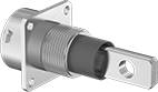
Male Panel-Mount Crimp-On Receptacles—External Housing Lock
 | 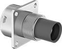 |
Front | Back |
UL 94 V-0—Connector insulation insert meets UL 94 V-0, so it resists catching fire.
Mounting | |||||||||||||||||
|---|---|---|---|---|---|---|---|---|---|---|---|---|---|---|---|---|---|
No. of Poles | Voltage | Current, amp | For Wire Ga. | For Panel Cutout Dia. | Lg. | Wd. | Ht. | Housing Material | Temp. Range, ° F | Connector Shell Size | Fasteners Included | No. of Holes | Hole Dia. | Flammability Rating | Each | ||
| 1 | 630V AC/630V DC | 86 | 8 | 0.71" | 1.5" | 1" | 1" | Nickel-Plated Zinc Alloy | -40 to 255 | 12 | No | 4 | 0.12" | UL 94 V-0 | 4577N11 | 000000 | |
Male Panel-Mount Tab Receptacles—External Housing Lock
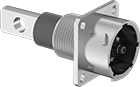 |  |
Front | Back |
UL 94 V-0—Connector insulation insert meets UL 94 V-0, so it resists catching fire.
Mounting | |||||||||||||||||
|---|---|---|---|---|---|---|---|---|---|---|---|---|---|---|---|---|---|
No. of Poles | Voltage | Current, amp | For Wire Ga. | For Panel Cutout Dia. | Lg. | Wd. | Ht. | Housing Material | Temp. Range, ° F | Connector Shell Size | Fasteners Included | No. of Holes | Hole Dia. | Flammability Rating | Each | ||
| 1 | 630V AC/630V DC | 86 | 8 | 0.71" | 2.2" | 1" | 1" | Nickel-Plated Zinc Alloy | -40 to 255 | 12 | No | 4 | 0.12" | UL 94 V-0 | 4577N12 | 000000 | |
