


Filter by
Maximum Pull
Electrical Connection
Wire Connection
DFARS Specialty Metals
Export Control Classification Number (ECCN)

About Magnets
Choose a magnet with the right strength, material, and temperature resistance for your application.
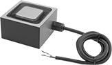
Hardwire Electromagnets
Rectangle
 |
Wattage, W | Wd. | Lg. | Ht. | Max. Pull, lbf | Sets of Poles | Max. Temp., ° F | Thread Size | Thread Dp. | No. of Mounting Holes | Mounting Hole Ctr.-to-Ctr. | Wire Lead Lg. | Each | |||
|---|---|---|---|---|---|---|---|---|---|---|---|---|---|---|---|
12V DC | |||||||||||||||
| 8 | 1 1/2" | 1 1/2" | 1 1/4" | 100 | 1 | 100 | 10-32 | 3/8" | 1 | — | 24" | 5698K311 | 0000000 | ||
| 10 | 1 1/2" | 2 1/2" | 1 1/4" | 160 | 1 | 100 | 10-32 | 3/8" | 2 | 1" | 24" | 5698K312 | 000000 | ||
| 14 | 2 1/2" | 2 1/2" | 1 1/2" | 300 | 1 | 100 | 1/4"-20 | 1/2" | 3 | 3/8" | 36" | 5698K313 | 000000 | ||
| 29 | 2 1/2" | 4 1/2" | 1 7/8" | 600 | 1 | 100 | 1/4"-20 | 3/4" | 2 | 2" | 36" | 5698K315 | 000000 | ||
24V DC | |||||||||||||||
| 8 | 1 1/2" | 1 1/2" | 1 1/4" | 100 | 1 | 100 | 10-32 | 3/8" | 1 | — | 24" | 5698K411 | 000000 | ||
| 10 | 1 1/2" | 2 1/2" | 1 1/4" | 160 | 1 | 100 | 10-32 | 3/8" | 2 | 1" | 24" | 5698K412 | 000000 | ||
| 14 | 2 1/2" | 2 1/2" | 1 1/2" | 300 | 1 | 100 | 1/4"-20 | 1/2" | 3 | 3/8" | 36" | 5698K413 | 000000 | ||
| 28 | 3 1/2" | 3 1/2" | 2" | 700 | 1 | 100 | 3/8"-16 | 3/4" | 1 | — | 36" | 5698K414 | 000000 | ||
| 29 | 2 1/2" | 4 1/2" | 1 7/8" | 600 | 1 | 100 | 1/4"-20 | 3/4" | 2 | 2" | 36" | 5698K415 | 000000 | ||
110V DC | |||||||||||||||
| 12 | 2 1/2" | 4 1/2" | 2" | 750 | 1 | 100 | 1/4"-20 | 1/2" | 2 | 2" | 24" | 5698K72 | 000000 | ||
| 37 | 3" | 6" | 2" | 1,000 | 1 | 100 | 3/8"-16 | 3/8" | 2 | 3" | 24" | 5698K71 | 000000 | ||
| 58 | 4" | 8" | 2 1/2" | 1,700 | 1 | 100 | 3/8"-16 | 1" | 2 | 4" | 36" | 5698K511 | 000000 | ||
| 65 | 6" | 12" | 3 1/2" | 5,000 | 1 | 100 | 1/2"-13 | 1 1/4" | 2 | 3" | 72" | 5698K74 | 00000000 | ||
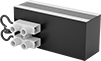
Hardwire Electromagnets with Parallel Poles
Rectangle
 |
Wattage, W | Wd. | Lg. | Ht. | Max. Pull, lbf | Sets of Poles | Max. Temp., ° F | Thread Size | Thread Dp. | No. of Mounting Holes | Mounting Hole Ctr.-to-Ctr. | Each | |||
|---|---|---|---|---|---|---|---|---|---|---|---|---|---|---|
24V DC | ||||||||||||||
| 5 | 1" | 2" | 1 3/8" | 80 | 1 | 100 | 1/4"-20 | 1/4" | 2 | 1" | 5684K16 | 0000000 | ||
| 7.8 | 1" | 3" | 1 3/8" | 170 | 1 | 100 | 1/4"-20 | 1/4" | 2 | 2" | 5684K17 | 000000 | ||
| 9.3 | 1" | 4" | 1 3/8" | 210 | 1 | 100 | 1/4"-20 | 1/4" | 2 | 3" | 5684K18 | 000000 | ||
| 18 | 1" | 6" | 1 3/8" | 260 | 1 | 100 | 1/4"-20 | 1/4" | 2 | 4 1/2" | 5684K19 | 000000 | ||
| 21 | 2" | 4" | 2 3/4" | 470 | 1 | 100 | 5/16"-18 | 1/4" | 2 | 3" | 5684K21 | 000000 | ||
| 30 | 2" | 6" | 2 3/4" | 620 | 1 | 100 | 5/16"-18 | 1/4" | 2 | 4 1/2" | 5684K22 | 000000 | ||
| 36 | 2" | 8" | 2 3/4" | 930 | 1 | 100 | 5/16"-18 | 1/4" | 2 | 6 1/2" | 5684K23 | 000000 | ||
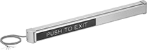
Electromagnetic Push Bars
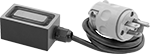
Plug-In Electromagnets
Rectangle
 |
Wattage, W | Wd. | Lg. | Ht. | Max. Pull, lbf | Sets of Poles | Max. Temp., ° F | Thread Size | Thread Dp. | No. of Mounting Holes | Mounting Hole Ctr.-to-Ctr. | Cord Lg., ft. | Each | |||
|---|---|---|---|---|---|---|---|---|---|---|---|---|---|---|---|
120V AC | |||||||||||||||
| 8 | 2 1/2" | 2 1/2" | 1 1/2" | 280 | 1 | 100 | 1/4"-20 | 1/2" | 2 | 3/4" | 3 | 5692K39 | 0000000 | ||
| 10 | 1 1/2" | 2 1/2" | 1 1/4" | 80 | 1 | 100 | 10-32 | 1/2" | 2 | 1" | 3 | 5692K36 | 000000 | ||
| 30 | 2 1/2" | 4 1/2" | 1 7/8" | 300 | 1 | 100 | 1/4"-20 | 1/2" | 2 | 2" | 3 | 5692K37 | 000000 | ||
