Filter by
Maximum Pull
Voltage
Length
Mount Type
Width
Wire Connection
Height
Electrical Connection
Threading
Sets of Poles
DFARS Specialty Metals
Export Control Classification Number (ECCN)
Maximum Temperature
Minimum Temperature

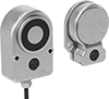
About Magnets
Choose a magnet with the right strength, material, and temperature resistance for your application.
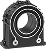
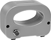
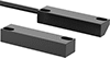
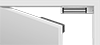
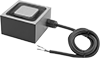
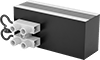
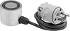
Electromagnets
Other Products