


Choosing an Electrical Switch
More
Enabling Pendant Switches
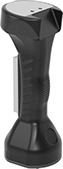
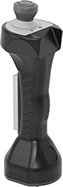
Also known as deadman switches, these switches make sure equipment only runs if you lightly press the hand grip. If you let go or a shock tightens your grip, they cut power. Use them when you need to override a system’s safety controls to program or service equipment. For example, if you need to be in a robot's working area to troubleshoot issues.
Switches with a Buna-N rubber housing work well in dirty and oily environments, such as machine shop floors, because they stand up to fuel oil, hydraulic oil, ethylene glycol, and grease. Because they have a cord on bottom, they can't stand up on their own. Add a mounting bracket to store them upright and out of the way.
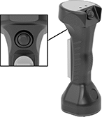
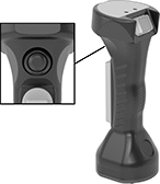
Switches with an auxiliary actuator give you control over more components in your system. Red emergency push buttons stop additional equipment with a single push. For example, you could shut down the conveying line a robot is working around. Black push buttons and rockers turn additional equipment, such as inspection lights, on and off.
Switches with a power indicator have red and green LEDs that light up to show whether power is running to your equipment.
Switches that meet EN 418 or EN 60947-5-1 comply with European safety standards for emergency stop applications.
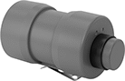
Top Push
Button
Emergency
Stop/Top Push Button
| No. of Circuits Controlled | Switch Starting Position | Switch Action | No. of Terminals | Industry Designation | Position Designation | Switching Current @ Voltage | Max. Voltage | Auxiliary Actuator Style (Industry Designation) | Environmental Rating | Specifications Met | Each | |
1 Speed with Screw Terminals | ||||||||||||
|---|---|---|---|---|---|---|---|---|---|---|---|---|
Switches | ||||||||||||
| 2 | 1 Off (Normally Open) or 1 On (Normally Closed) | Springs Back (Momentary) | 3 | SPDT | Off-(On)-Off | 0.5 A @ 250 V AC, 0.1 A @ 125 V DC | 125V DC 250V AC | __ | IP66 | UL Listed C-UL Listed CE Marked | 0000000 | 0000000 |
| 2 | 1 Off (Normally Open) or 1 On (Normally Closed) | Springs Back (Momentary) | 3 | SPDT | Off-(On)-Off | 0.5 A @ 250 V AC, 0.1 A @ 125 V DC | 125V DC 250V AC | 1 Top Black Push Button (SPDT) | IP65 | UL Listed C-UL Listed CE Marked | 0000000 | 000000 |
Switches with Emergency Stop Button | ||||||||||||
| 2 | 1 Off (Normally Open) or 1 On (Normally Closed) | Springs Back (Momentary) | 3 | SPDT | Off-(On)-Off | 0.5 A @ 250 V AC, 0.1 A @ 125 V DC | 125V DC 250V AC | 1 Top Red Push Button (DPST-NC) | IP65 | UL Listed C-UL Listed CE Marked EN 60947-5-1 | 0000000 | 000000 |

Emergency
Stop/Top Push Button
| No. of Circuits Controlled | Switch Starting Position | Switch Action | No. of Terminals | Industry Designation | Position Designation | Switching Current @ Voltage | Max. Voltage | Auxiliary Actuator Style (Industry Designation) | Environmental Rating | Specifications Met | Each | |
1 Speed with Screw Terminals | ||||||||||||
|---|---|---|---|---|---|---|---|---|---|---|---|---|
Switches with Power Indicator | ||||||||||||
| 1 | 1 Off (Normally Open) or 1 On (Normally Closed) | Springs Back (Momentary) | 3 | SPDT | Off-(On)-Off | 1 A @ 30 V DC | 30V DC | __ | IP65, IP67 | UL Listed C-UL Listed CE Marked | 0000000 | 0000000 |
| 1 | 1 Off (Normally Open) or 1 On (Normally Closed) | Springs Back (Momentary) | 3 | SPDT | Off-(On)-Off | 1 A @ 30 V DC | 30V DC | 1 Front Black Push Button (SPST-NO) | IP65, IP67 | UL Listed C-UL Listed CE Marked | 0000000 | 000000 |
| 1 | 1 Off (Normally Open) or 1 On (Normally Closed) | Springs Back (Momentary) | 3 | SPDT | Off-(On)-Off | 1 A @ 30 V DC | 30V DC | 1 Front Black Push Button (SPST-NO), 1 Top Black Push Button (SPST-NO) | IP65, IP67 | UL Listed C-UL Listed CE Marked | 0000000 | 000000 |
| 1 | 1 Off (Normally Open) or 1 On (Normally Closed) | Springs Back (Momentary) | 3 | SPDT | Off-(On)-Off | 1 A @ 30 V DC | 30V DC | 1 Front Black Push Button (SPST-NO), 1 Top Black Rocker (SPST-NO) | IP65, IP67 | UL Listed C-UL Listed CE Marked | 0000000 | 000000 |
Switches with Emergency Stop Button and Power Indicator | ||||||||||||
| 1 | 1 Off (Normally Open) or 1 On (Normally Closed) | Springs Back (Momentary) | 3 | SPDT | Off-(On)-Off | 1 A @ 30 V DC | 30V DC | 1 Top Red Push Button (SPDT) | IP65, IP67 | UL Listed C-UL Listed CE Marked EN 418 | 0000000 | 000000 |
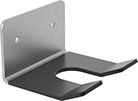
Mounting | |||||
|---|---|---|---|---|---|
| Material | Fasteners Included | No. of Holes | Hole Dia. | Each | |
| Plastic-Coated Stainless Steel | No | 2 | 3/16" | 0000000 | 000000 |
Wireless Enabling Pendant Switches
As soon as you take your thumb off the button, these switches wirelessly signal a receiver to cut power to your machine. Also known as deadman switches. Use them when you need to override safety controls to program or service a machine. They’re often used to troubleshoot issues in a robot's working area.
900 MHz switches can be used in any combination of six. Stop multiple machines with one switch, set multiple switches to stop one machine, or anything in between. If you link multiple switches to one receiver, your machine will stop if just one person takes their thumb off their switch. These switches are compatible with frequencies found in U.S. systems.
2.4 GHz switches control up to nine machines if paired with nine receivers. These switches are compatible with frequencies found in European systems.
Antenna extension cords (sold separately) connect a receiver to an antenna, so you can keep the receiver safe inside an enclosure.
| No. of Circuits Controlled | Switch Starting Position | Switch Action | Housing Material | Batteries Included | Battery Life, hrs. | Environmental Rating | Specifications Met | Includes | Each | |
900 MHz Transmission Frequency | ||||||||||
|---|---|---|---|---|---|---|---|---|---|---|
| 5 | 1 Off (Normally Open) | Springs Back (Momentary) | Red Plastic | Yes | 34 | IP64 | IEC 61508 SIL2, ISO 13849-1 PLd | Charging Cord (Magnetic Charger × USB A) | 0000000 | 0000000 |
2.4 GHz Transmission Frequency | ||||||||||
| 9 | 1 Off (Normally Open) | Springs Back (Momentary) | Red Plastic | Yes | 16 | __ | IEC 61508 SIL2, ISO 13849-1 PLd | Charging Cord (USB Micro B × USB A) | 0000000 | 000000 |
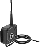
Receivers | |||||||||||||
|---|---|---|---|---|---|---|---|---|---|---|---|---|---|
Wire Leads | Mounting | Antenna Extension Cords | |||||||||||
| Wire Connection Type | No. of | Lg. | Input Voltage | Housing Material | Fasteners Included | No. of Holes | Hole Dia. | Cable Lg., ft. | Specifications Met | Each | Each | ||
900 MHz Transmission Frequency | |||||||||||||
| Wire Leads | 4 | 3" | 9V DC-30V DC | Black Plastic | No | 2 | 3/16" | 3 | IEC 61508 SIL2, ISO 13849-1 PLd | 0000000 | 0000000 | 0000000 | 000000 |
| Wire Leads | 6 | 3" | 100V AC-240V AC | Black Plastic | No | 2 | 3/16" | 3 | IEC 61508 SIL2, ISO 13849-1 PLd | 0000000 | 000000 | 0000000 | 00000 |
2.4 GHz Transmission Frequency | |||||||||||||
| Wire Leads | 4 | 3" | 9V DC-30V DC | Black Plastic | No | 2 | 3/16" | 3 | IEC 61508 SIL2, ISO 13849-1 PLd | 0000000 | 000000 | 0000000 | 00000 |
| Wire Leads | 6 | 3" | 100V AC-240V AC | Black Plastic | No | 2 | 3/16" | 3 | IEC 61508 SIL2, ISO 13849-1 PLd | 0000000 | 000000 | 0000000 | 00000 |
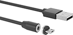
| Connection Type | Lg., ft. | Environment | Environmental Rating | Each | |
| Magnetic Charger × USB A | 3 | Damp, Dusty | IP64 | 0000000 | 000000 |
| Connection Type | Lg., ft. | Each | |
| USB Micro B × USB A | 3 | 00000000 | 00000 |