McMaster-Carr logo
    Filter by
    System of Measurement
    Gear Box Input Connection
    Encoder Output Channel Type
    Number of Output Channels
    Number of Mounting Holes
    For Maximum Shaft Speed
    Export Control Classification Number (ECCN)
    Industrial Info Snippet
    U.S.–Mexico–Canada Agreement (USMCA) Qualifying
    DFARS Specialty Metals
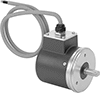
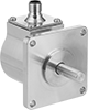
    Enter e-mail addresses in the fields below
    Message
    Cancel
    Comments
    E-mail address (if you would like a response)
    127 Products

    Compact Rotary Encoders

    Track distance, direction, and speed in tight spaces on machinery. Cylindrical and about half the size of standard position-measuring transmitters, these are often used on robot arms and crowded conveyors. Also known as encoders, they send motion data to your system by converting rotary motion into an electrical signal.
    Incremental Optical Encoders with Shaft
    Image of Product. Front orientation. Contains Annotated. Rotary Encoders. Compact Rotary Encoders, Shaft Gear Box Input, Wire Lead Connection—NPN Open Collector.
    Image of Product. Front orientation. Contains Annotated. Rotary Encoders. Compact Rotary Encoders, Shaft Gear Box Input, 5-Pole Micro M12 Plug-In Connection—IO Link.

    Wire Lead

    Connection—NPN Open

    Collector

    5-Pole Micro M12

    Plug-In

    Connection—IO Link

    Incremental transmitters track how much a rotating shaft has turned relative to a reference point. They need to be reset after a power loss.
    Transmitters with a shaft connect to a motor’s shaft with a flexible shaft coupling to fit different diameters.
    NPN Open Collector—Transmitters with an NPN open collector pair with a resistor. Use these transmitters with a controller that has quadrature detection to get a 4X resolution increase.
    IO Link Communication Protocol—Transmitters with IO link let you set their resolution remotely when connected to a PLC, a human-machine interface (HMI), or a computer.
    IP64 Enclosure Rating and IP65 Enclosure Rating—IP-rated transmitters are protected from dust and water.
    Encoders
    Connectors
    Mounting
    Holes
    Shaft
    Dia.
    Rotary Encoder
    Type
    Input Voltage,
    V DC
    Max. Input
    Current, mA
    Output Current,
    mA
    Encoder Output
    Channel Type
    For Max. Shaft
    Speed, rpm
    Body Material
    Housing
    Material
    Enclosure
    Rating
    No.
    of
    Thread
    Size
    Fasteners
    Included
    Choose a Resolution
    Each
    Each
    Wire Lead Connection—NPN Open Collector
    1/4"Single Turn5 to 286520Quadrature with Index8,000Aluminum
    PlasticIP64
    3M3 × 0.5 mmNo
    500
    ,
    1,000
    ,
    2,000
    ,
    2,500
    0000000000000———0
     
    5-Pole Micro M12 Plug-In Connection—IO Link
    6 mmSingle Turn5 to 301505012,000Stainless Steel
    Aluminum
    IP65
    3M4 × 0.7 mmNo1 to 10,000000000000000000000000000000
    10 mmSingle Turn5 to 301505012,000Stainless Steel
    Aluminum
    IP65
    3M4 × 0.7 mmNo1 to 10,00000000000000000000000000000
     
    Incremental Optical Encoders with Shaft Opening
    Image of Product. Front orientation. Contains Annotated. Rotary Encoders. Compact Rotary Encoders, Shaft-Opening Gear Box Output, Wire Lead Connection—NPN Open Collector.
    Image of Product. Front orientation. Contains Annotated. Rotary Encoders. Compact Rotary Encoders, Shaft-Opening Gear Box Output, 5-Pole Micro M12 Plug-In Connection—IO Link.

    Wire Lead

    Connection—NPN

    Open Collector

    5-Pole Micro M12 Plug-In

    Connection—IO Link

    Incremental transmitters track how much a rotating shaft has turned relative to a reference point. They need to be reset after a power loss.
    Transmitters with a shaft opening slide onto your motor's shaft. Their mounting plate flexes to compensate for your motor's vibration.
    NPN Open Collector—Transmitters with an NPN open collector pair with a resistor. Use these transmitters with a controller that has quadrature detection to get a 4X resolution increase.
    IO Link Communication Protocol—Transmitters with IO link let you set their resolution remotely when connected to a PLC, a human-machine interface (HMI), or a computer.
    IP64 Enclosure Rating and IP65 Enclosure Rating—IP-rated transmitters are protected from dust and water.
    Encoders
    Connectors
    Mounting Holes
    For Shaft
    Dia.
    Rotary Encoder
    Type
    Input Voltage,
    V DC
    Max. Input
    Current, mA
    Output Current,
    mA
    Encoder Output
    Channel Type
    For Max. Shaft
    Speed, rpm
    Body Material
    Housing
    Material
    Enclosure
    Rating
    Mounting
    Plate Dia.
    Mounting
    Plate Wd.
    For Screw
    Size
    No.
    of
    Ctr.-to-Ctr.
    Thread Size
    Fasteners
    Included
    Choose a Resolution
    Each
    Each
    Wire Lead Connection—NPN Open Collector
    1/4"Single Turn5 to 286520Quadrature with Index8,000Aluminum
    PlasticIP64
    2.16"No. 6
    21.81"No
    500
    ,
    1,000
    ,
    2,000
    ,
    2,500
    0000000000000———0
    3/8"Single Turn5 to 286520Quadrature with Index8,000Aluminum
    PlasticIP64
    2.16"No. 6
    21.81"No
    500
    ,
    1,000
    ,
    2,000
    ,
    2,500
    000000000000———0
     
    5-Pole Micro M12 Plug-In Connection—IO Link
    6 mmSingle Turn5 to 301505012,000Stainless Steel
    Aluminum
    IP65
    1.43"4M2.5 × 0.5 mmNo1 to 10,000000000000000000000000000000
    10 mmSingle Turn5 to 301505012,000Stainless Steel
    Aluminum
    IP65
    1.43"4M2.5 × 0.5 mmNo1 to 10,00000000000000000000000000000
     
    Absolute Optical Encoders with Shaft
    Image of Product. Front orientation. Contains Annotated. Rotary Encoders. Compact Rotary Encoders, Shaft Gear Box Input, Wire Lead Connection—Synchronous Serial Interface (SSI).
    Image of Product. Front orientation. Contains Annotated. Rotary Encoders. Compact Rotary Encoders, Shaft Gear Box Input, 5-Pole Micro M12 Plug-In Connection—IO Link.

    Wire Lead

    Connection—Synchronous

    Serial Interface (SSI)

    5-Pole Micro M12

    Plug-In

    Connection—IO Link

    Absolute transmitters give you the exact position of the shaft, even after a power loss.
    Transmitters with a shaft connect to a motor’s shaft with a flexible shaft coupling to fit different diameters.
    IO Link Communication Protocol—Transmitters with IO link let you set their resolution remotely when connected to a PLC, a human-machine interface (HMI), or a computer.
    Multi-Turn Rotary Encoder—Multi-turn absolute transmitters count how many full turns a shaft makes. They’re often used to keep print rollers aligned over multiple rotations.
    IP65 Enclosure Rating—IP-rated transmitters are protected from dust and water.
    Encoders
    Connectors
    Mounting
    Holes
    Shaft
    Dia.
    Rotary Encoder
    Type
    Input Voltage,
    V DC
    Max. Input
    Current, mA
    Output Current,
    mA
    For Max. Shaft
    Speed, rpm
    Body Material
    Housing
    Material
    Enclosure
    Rating
    No.
    of
    Thread
    Size
    Fasteners
    Included
    Bit Resolution,
    bit
    Each
    Each
    Wire Lead Connection—Synchronous Serial Interface (SSI)
    1/4"Single Turn5 to 325010012,000Aluminum
    Stainless Steel
    IP65
    4M3 × 0.5 mmNo12000000000000000———0
    1/4"Multi-Turn5 to 325010012,000Aluminum
    Stainless Steel
    IP65
    4M3 × 0.5 mmNo2400000000000000———0
    6 mmSingle Turn5 to 325010012,000Aluminum
    Stainless Steel
    IP65
    4M3 × 0.5 mmNo1200000000000000———0
    6 mmMulti-Turn5 to 325010012,000Aluminum
    Stainless Steel
    IP65
    4M3 × 0.5 mmNo2400000000000000———0
     
    5-Pole Micro M12 Plug-In Connection—IO Link
    6 mmMulti-Turn18 to 30755012,000Stainless Steel
    Aluminum
    IP65
    3M4 × 0.7 mmNo1 to 31000000000000000000000000000
    10 mmMulti-Turn18 to 30755012,000Stainless Steel
    Aluminum
    IP65
    3M4 × 0.7 mmNo1 to 3100000000000000000000000000
     
    Absolute Optical Encoders with Shaft Opening
    Image of Product. Front orientation. Contains Annotated. Rotary Encoders. Compact Rotary Encoders, Shaft-Opening Gear Box Output, Wire Lead Connection—Synchronous Serial Interface (SSI).

    Wire Lead

    Connection—Synchronous

    Serial Interface (SSI)

    Absolute transmitters give you the exact position of the shaft, even after a power loss.
    Transmitters with a shaft opening slide onto your motor's shaft. Their mounting plate flexes to compensate for your motor's vibration.
    Multi-Turn Rotary Encoder—Multi-turn absolute transmitters count how many full turns a shaft makes. They’re often used to keep print rollers aligned over multiple rotations.
    Mounting
    Holes
    For Shaft
    Dia.
    Rotary Encoder
    Type
    Input Voltage,
    V DC
    Max. Input
    Current, mA
    Output Current,
    mA
    For Max. Shaft
    Speed, rpm
    Body
    Material
    Housing
    Material
    Mounting
    Plate Wd.
    For Screw
    Size
    No.
    of
    Ctr.-to-Ctr.
    Fasteners
    Included
    Bit Resolution,
    bit
    Each
    Wire Lead Connection—Synchronous Serial Interface (SSI)
    1/4"Single Turn5 to 241004208,000Aluminum
    Plastic2.16"No. 6
    21.81"No12000000000000000
    1/4"Multi-Turn5 to 241004208,000Aluminum
    Plastic2.16"No. 6
    21.81"No2400000000000000
    3/8"Single Turn5 to 241004208,000Aluminum
    Plastic2.16"No. 6
    21.81"No1200000000000000
    3/8"Multi-Turn5 to 241004208,000Aluminum
    Plastic2.16"No. 6
    21.81"No2400000000000000
     

    Rotary Encoders

    Provide motion feedback to counters, controllers, and motor drives for automated motion control and measurement applications. Also known as encoders, transmitters convert rotary motion to an electrical signal so you can operate your system based on distance, direction, and speed of travel. These transmitters have pull-up resistor output. Since they have two shafts, you can mount them on either side to fit your setup.
    Use a flexible shaft coupling (not included) to connect the transmitter shaft to a drive shaft.
    Aluminum Body and Stainless Steel Shaft
    Image of Product. Shown with Wheel and Mounting Bracket (Both Sold Separately). Front orientation. Contains Annotated. Rotary Encoders. Rotary Encoders.
    Image of Product. Front orientation. Contains Annotated. Rotary Encoders. Rotary Encoders.

    Shown with Wheel and Mounting

    Bracket (Both Sold Separately)

    Quadrature Output Channel—Transmitters with a quadrature output channel must be used with a controller that has quadrature detection to get a 4X resolution increase.
    Shaft
    Overall
    Mounting
    Plate
    Mounting
    Holes
    For Counter
    Function
    Encoder Output
    Channel
    Resolution
    Increase
    For Max. Shaft
    Speed, rpm
    Input Voltage,
    V DC
    Coupling
    Req.
    Dia.
    Lg.
    Lg.
    Ht.
    Lg.
    Wd.
    Ctr.-to-Ctr.
    Thread
    Size
    Choose a Resolution
    Each
    Single Output Channel—250 mA Output Current
    UpA2X6,0005 to 28Yes3/8"3/4"3.95"2.93"2 1/4"2 1/4"1.41"6-32
    10
    ,
    60
    ,
    100
    ,
    120
    ,
    500
    ,
    600
    ,
    1,200
    000000000000000
     
    Quadrature Output Channel—250 mA Output Current
    Up and DownA, B2X, 4X6,0005 to 28Yes3/8"3/4"3.95"2.93"2 1/4"2 1/4"1.41"6-32
    10
    ,
    60
    ,
    100
    ,
    120
    ,
    500
    ,
    600
    ,
    1,200
    00000000000000
     
    Accessories for Rotary Encoders

    Rotary Encoder Kits

    Image of Product. Shown with Wheel (Sold Separately). Front orientation. Rotary Encoders. Rotary Encoder Kits.
    Image of Product. Front orientation. Contains Annotated. Rotary Encoders. Rotary Encoder Kits.

    Shown with Wheel

    (Sold Separately)

    In addition to a transmitter, these kits include a 6 1/2-ft. cable and a mounting bracket. Also known as encoders, transmitters convert motion to an electrical signal to indicate distance, direction, and speed in process control and metering applications. These kits are commonly used to monitor the position or velocity of rotating equipment. You can also mount a wheel (not included) to measure distance in linear applications. Transmitters must be used with a controller that has quadrature detection to get a 4X resolution increase. Output channel Z is also known as an index channel.
    Use a flexible shaft coupling (not included) to connect the transmitter shaft to a drive shaft.
    For Counter
    Function
    Encoder Output
    Channel
    Resolution
    Increase
    For Max. Shaft
    Speed, rpm
    Input Voltage,
    V DC
    Output Current,
    mA
    Resistor
    Included
    Body
    Material
    Shaft Material
    Fasteners
    Included
    Fasteners
    Req.
    For Mounting
    Screw Size
    Choose a Resolution
    Each
    Quadrature with Index Output Channel
    Up and DownA, B, Z2X, 4X6,0005 to 2820NoPlasticStainless Steel
    NoYes1/4"
    500
    ,
    600
    ,
    1,000
    ,
    1,800
    ,
    2,500
    000000000000000
     
    Wheels

    Linear Motion Position-Measuring Transmitters

    Image of Product. Front orientation. Linear Motion Position-Measuring Transmitters. Style 1.
    Image of Product. Front orientation. Linear Motion Position-Measuring Transmitters. Style 2.
    Image of Product. Front orientation. Linear Motion Position-Measuring Transmitters. Style 3.
    Image of Product. Front orientation. Linear Motion Position-Measuring Transmitters. Style 4.

    Style 1

    Style 2

    Style 3

    Style 4

    Image of Attribute. Styles 1-4. Front orientation. Contains Annotated.

    Styles 1-4

    Image of Specification. 4-Pole M12 Plug. Front orientation. 4 Poles.

    4-Pole

    M12

    Plug

    Image of Specification. 5-Pole M12 Plug. Front orientation. 5 Poles.

    5-Pole

    M12

    Plug

    Track the position of hydraulic cylinders and other components that move in a straight line. Like a tape measure, these transmitters have a wire that extends to measure how far components have traveled from a set point. Because of the wire, they're also known as string pots—short for string potentiometers. They convert measurements to an electrical signal, which can then be used to trigger automated actions in your process.
    Plug In—Transmitters with a plug are quicker to connect and disconnect than those with wire leads. Plug them into a cable with a socket (sold separately).
    IP67 Enclosure Rating—All are IP rated for some protection from dust. Transmitters rated IP67 seal out water when briefly submersed.
    Transmitters
    Cables
    with Socket
    Overall
    Mounting Holes
    Stroke
    Lg.
    Percentage Accuracy
    Range
    Repeatability Percentage
    Range
    Max. Input
    Voltage
    Input Resistance,
    kohm
    Output
    Signal
    Housing
    Material
    Enclosure
    Rating
    Wire Lead
    Lg.
    Eyelet
    ID
    Lg.
    Wd.
    Ht.
    Ctr.-to-Ctr.
    Dia.
    No.
    of
    Each
    Each
    Style 1
     
    Wire Leads
    4 3/4"-1% to 1%-0.05% to 0.05%30V AC
    30V DC
    100-28.2V AC
    0-28.2V DC
    PlasticIP50
    40"0.191"3.1"1.9"2.6"(A) 1.4"1/8"20000000000000———0
    12 1/2"-0.25% to 0.25%-0.05% to 0.05%30V AC
    30V DC
    100-28.2V AC
    0-28.2V DC
    PlasticIP50
    40"0.191"3.1"1.9"2.6"(A) 1.4"1/8"2000000000000———0
    25"-0.25% to 0.25%-0.05% to 0.05%30V AC
    30V DC
    100-28.2V AC
    0-28.2V DC
    PlasticIP50
    40"0.191"3.1"1.9"2.6"(A) 1.4"1/8"2000000000000———0
    50"-0.25% to 0.25%-0.05% to 0.05%30V AC
    30V DC
    100-28.2V AC
    0-28.2V DC
    PlasticIP50
    40"0.191"3.1"1.9"2.6"(A) 1.4"1/8"2000000000000———0
     
    Style 2
     
    Wire Leads
    120"-0.35% to 0.35%-0.05% to 0.05%30V AC
    30V DC
    100-28.2V AC
    0-28.2V DC
    PlasticIP67
    40"0.191"2.48"5.17"5.09"(A) 4 3/4"
    (B) 4.62"
    (C) 2.2"
    7/32"
    3/16"
    3/16"
    6000000000000———0
     
    With 4-Pole M12 Plug
    120"-0.35% to 0.35%-0.05% to 0.05%30V AC
    30V DC
    100-28.2V AC
    0-28.2V DC
    PlasticIP67
    0.191"2.48"5.17"5.09"(A) 4 3/4"
    (B) 4.62"
    (C) 2.2"
    7/32"
    3/16"
    3/16"
    6000000000000000000000000000
     
    Style 3
     
    With 5-Pole M12 Plug
    75"-0.02% to 0.02%-0.006% to 0.006%32V DC4.84 mA to 20 mASteelIP64
    0.197"4.11"3.11"3.27"(A) 0.98"7/32"200000000000000000000000000
     
    Style 4
     
    With 5-Pole M12 Plug
    118"-0.012% to 0.012%-0.005% to 0.005%32V DC4.84 mA to 20 mASteelIP64
    0.083"3.61"3.07"3.58"(A) 2.32"
    (B) 2.44"
    3/16"
    3/16"
    800000000000000000000000000
     

    Sanitary Rotary Encoders

    Image of Product. Front orientation. Contains Annotated. Rotary Encoders. Sanitary Rotary Encoders.
    Also known as encoders, these sanitary transmitters convey motion to an electrical signal that conveys distance, direction, and speed. They’re often used in control systems to automate servomotors, robotics, and assembly machines in sanitary environments such as food and pharmaceutical plants. Made of corrosion-resistant stainless steel, they won’t rust from frequent washdowns with harsh cleaners. These transmitters are sealed and have a highly polished surface, leaving no room for bacteria to grow and making them easier to clean. They’re rated IP67 for protection from dust, high-pressure jets of water, and submersion in up to a meter of water for 30 minutes.
    To achieve a 4X resolution increase, use these transmitters with a controller that has quadrature detection.
    Use a flexible shaft coupling to connect the transmitter shaft to a drive shaft.
    316 Stainless Steel Body and 303 Stainless Steel Shaft
    Shaft
    Overall
    Mounting
    Plate
    Mounting Holes
    For Counter
    Function
    Encoder Output
    Channel
    Resolution
    Resolution
    Increase
    For Max. Shaft
    Speed, rpm
    Input Voltage,
    V DC
    Coupling
    Req.
    Dia.
    Lg.
    Lg.
    Ht.
    Lg.
    Wd.
    No.
    of
    Ctr.-to-Ctr.
    Dia.
    Certification
    Each
    Quadrature with Index Output Channel—20 mA Output Current
    Up and DownA, B, Z6002X, 4X8,0004.75 to 28Yes3/8"1 1/16"3.175"3 1/4"2 1/2"2 1/2"42.06"7/32"CE Marked
    00000000000000000
    Up and DownA, B, Z3,6002X, 4X8,0004.75 to 28Yes3/8"1 1/16"3.175"3 1/4"2 1/2"2 1/2"42.06"7/32"CE Marked
    0000000000000000
     
    Cables

    Programmable Rotary Encoders

    With adjustable settings for resolution and output type, these transmitters can be programmed to suit your changing processes. Also known as encoders, they convert a shaft’s rotary motion into an electrical signal that indicates distance, direction, and speed. They’re rated IP67, so they can withstand temporary submersion in water.
    Encoders with Shaft
    Image of Product. Front orientation. Rotary Encoders. Programmable Rotary Encoders, Encoders with Shaft.
    Transmitters with a shaft connect to motor shafts with a flexible shaft coupling, so they can be adapted to different diameters.
    Shaft
    Dia.
    Encoder Output Signal
    Input Voltage,
    V DC
    Max. Input
    Current, mA
    Output Current,
    mA
    For Max. Shaft
    Speed, rpm
    Body
    Material
    Housing
    Material
    Enclosure
    Rating
    Mounting Hole
    Thread Size
    Fasteners
    Included
    Resolution
    Each
    Incremental Optical Encoder
    1/4"Line Driver, NPN Open Collector, Push-Pull5 to 3065208,000Aluminum
    Aluminum
    IP67
    10-32
    No1 to 65,536000000000000000
    3/8"Line Driver, NPN Open Collector, Push-Pull5 to 3065208,000Aluminum
    Aluminum
    IP67
    10-32
    No1 to 65,53600000000000000
     
    Rotary Encoder Programming Kits
    Encoders with Shaft Opening
    Image of Product. Front orientation. Rotary Encoders. Programmable Rotary Encoders, Encoders with Shaft Opening.
    Transmitters with a shaft opening can be mounted anywhere along a motor shaft—just slide them on. They have a flexible mounting plate that compensates for shaft misalignment and vibration.
    For Shaft
    Dia.
    Encoder Output Signal
    Input Voltage,
    V DC
    Max. Input
    Current, mA
    Output Current,
    mA
    For Max. Shaft
    Speed, rpm
    Body
    Material
    Housing
    Material
    Enclosure
    Rating
    Mounting
    Plate Wd.
    For Screw
    Size
    Fasteners
    Included
    Resolution
    Each
    Incremental Optical Encoder
    1/4"Line Driver, NPN Open Collector, Push-Pull5 to 3065206,000Aluminum
    Aluminum
    IP67
    2.83"No. 6
    No1 to 65,536000000000000000
    3/8"Line Driver, NPN Open Collector, Push-Pull5 to 3065206,000Aluminum
    Aluminum
    IP67
    2.83"No. 6
    No1 to 65,53600000000000000
     
    Rotary Encoder Programming Kits

    Stepper Motors

    Motor/Encoders
    Image of Product. Front orientation. Stepper Motors. Motor/Encoders.
    Image of Attribute. Front orientation. Contains Annotated. Motor/Encoders.
    Image of Attribute. Side1 orientation. Contains Annotated. Motor/Encoders.
    To improve positioning accuracy, these stepper motors have a built-in encoder that monitors the real-time speed and position of the shaft. It sends that data to a controller (not included), which adjusts or stops the shaft if it isn’t in the right place. This makes them useful when relative positioning is critical, such as when coordinating motion between two motors. Stepper motors are good for precise, repetitive movements. Similar to the hands of a clock, their shaft turns in small, equal increments for smooth motion. When the shaft stops, it holds its position even when a counteracting force is applied to the load. All are bipolar hybrid stepper motors, so the current can flow in both directions. This helps them deliver higher torque, precision, and efficiency than unipolar stepper motors.
    All motors require a controller and drive (not included).
    2 Shafts—When relative positioning is critical, such as coordinating motion in a multi-axis system, choose a motor with two shafts and mount an encoder (not included) on one of them. The encoder monitors the position of the shaft and reports back to the controller.
    Maximum Holding Torque—Holding torque is the force needed to move the shaft out of position when it is stationary. When the shaft is in motion, torque generally decreases as speed increases. Use a torque-speed curve to confirm which motor will work for your application. Click on a part number and select “Product Detail” to view the curve for a motor.
    Full Step Increment—Full step increment is the rotation of the shaft from one position to the next. A smaller full step increment means the rotor has more teeth, producing smoother and more precise motion. 1.8° is considered standard.
    Overall
    Shaft
    Temp.
    Range, ° F
    Max. Holding
    Torque, in·ozf
    Max. Rotation
    Speed, rpm
    Max. Current
    per Phase, amp
    Voltage,
    V DC
    Full Step
    Increment
    Stepper Motor
    Polarity
    Encoder Positioning
    Type
    No. of Counts
    per Rev.
    No. of Wire
    Leads
    Lg.
    Wd.
    Ht.
    Dia.
    Lg.
    Ctr.-to-Base
    Lg.
    Type
    No. of
    Shafts
    Min.
    Max.
    Each
    Square Body
     
    NEMA 17 Frame Size
    26.91,5000.6751.8°BipolarIncremental1,00042.6"2.3"1.7"5 mm22 mm0.84"D-Profile20120000000000000000
    399000.6251.8°BipolarIncremental1,00042.8"2.3"1.7"5 mm22 mm0.84"Solid2012000000000000000
    647500.751.8°BipolarIncremental1,00043"2.3"1.7"5 mm22 mm0.84"Solid2012000000000000000
    70.83,000251.8°BipolarIncremental1,00043.2"2.3"1.7"5 mm22 mm0.84"D-Profile2012000000000000000
    83.58251.0551.8°BipolarIncremental1,00043.5"2.3"1.7"5 mm22 mm0.84"D-Profile2012000000000000000
    124.61,400251.8°BipolarIncremental1,00043.9"2.3"1.7"5 mm22 mm0.84"D-Profile2012000000000000000
     
    NEMA 23 Frame Size
    1816002.851.8°BipolarIncremental1,00043.7"2.6"2.3"1/4"3/4"1.13"D-Profile2012000000000000000
    237525451.8°BipolarIncremental1,00044.6"2.6"2.3"1/4"3/4"1.13"D-Profile2012000000000000000
    355900651.8°BipolarIncremental1,00044.9"2.6"2.3"1/4"3/4"1.13"D-Profile2012000000000000000
    467.3300251.8°BipolarIncremental1,00044.5"2.5"2.3"1/4"3/4"1.11"D-Profile2012000000000000000
    600.41,3006.551.8°BipolarIncremental1,00044.9"2.6"2.3"1/4"3/4"1.13"D-Profile2012000000000000000
     

    Stepper Motors with Integrated Motion Control

    Image of Product. Front orientation. Stepper Motors. Stepper Motors with Integrated Motion Control.
    With a built-in controller and drive, these stepper motors come ready to program and operate. Connect them to a computer and use the free downloadable software to set them up. After that, the controller can store and run programs on its own. The controller communicates to the drive which directs the motor’s shaft to move in small, equal increments. When the shaft stops, it holds its position even when a counteracting force is applied to the load. All are bipolar hybrid stepper motors, which deliver greater torque, precision, and efficiency than other types of stepper motors.
    Encoders—When relative positioning is critical, such as coordinating motion in a multi-axis system, choose a motor with an encoder. The encoder monitors the position of the shaft and reports back to the controller.
    Maximum Holding Torque—Holding torque is the force needed to move the shaft out of position when it is stationary. When the shaft is in motion, torque generally decreases as speed increases. Use a torque-speed curve to confirm which motor will work for your application. Click on a part number and select “Product Detail” to view the curve for a motor.
    Full Step Increment—Full step increment is the rotation of the shaft from one position to the next. A smaller full step increment means the rotor has more teeth, producing smoother and more precise motion. 1.8° is considered standard.
    Step Resolution—You can adjust the step resolution down to 1/256 of a full step, which translates to 51,200 microsteps per revolution. Increasing the number of steps directs an even more precise position and reduces the step-step-step motion to mimic a smooth, continuous rotation. The higher the number of step resolution settings, the greater the flexibility you have for determining the size of the motor’s step.
    Current per
    Phase, amp
    Overall
    Shaft
    Temp.
    Range, ° F
    Max. Holding
    Torque, in·ozf
    Max. Rotation
    Speed, rpm
    Min.
    Max.
    Voltage,
    V DC
    Full Step
    Increment
    Step Resolution
    No. of Inputs/Outputs
    Lg.
    Wd.
    Ht.
    Dia.
    Lg.
    Ctr.-to-Base
    Lg.
    Type
    Min.
    Max.
    Each
    Motor/Controller/Drive/Encoders
     
    NEMA 17 Frame Size
    313,0000.12.212 to 481.8°1 to 1/2561 Analog-Input,
    3 Digital-Inputs,
    1 Digital-Output
    3.7"1.7"3"5 mm22 mm0.84"D-Profile35100000000000000000
    543,0000.12.212 to 481.8°1 to 1/2561 Analog-Input,
    3 Digital-Inputs,
    1 Digital-Output
    3.9"1.7"3"5 mm22 mm0.84"D-Profile3510000000000000000
    683,0000.12.212 to 481.8°1 to 1/2561 Analog-Input,
    3 Digital-Inputs,
    1 Digital-Output
    4.2"1.7"3"5 mm22 mm0.84"D-Profile3510000000000000000
     
    NEMA 23 Frame Size
    100.52,4750.3312 to 401.8°1, 1/2, 1/4, 1/8, 1/16, 1/32, 1/64, 1/128, 1/2564 Digital-Inputs/Outputs3.8"2.3"2.3"1/4"3/4"1.13"D-Profile012000000000000000
    182.52,0000.3312 to 401.8°1, 1/2, 1/4, 1/8, 1/16, 1/32, 1/64, 1/128, 1/2564 Digital-Inputs/Outputs4.3"2.3"2.3"1/4"3/4"1.13"D-Profile012000000000000000
    294.58200.3312 to 401.8°1, 1/2, 1/4, 1/8, 1/16, 1/32, 1/64, 1/128, 1/2564 Digital-Inputs/Outputs5.1"2.3"2.3"1/4"3/4"1.13"D-Profile012000000000000000
     
    NEMA 24 Frame Size
    3402,4003512 to 701.8°1 to 1/2561 Analog-Input,
    4 Digital-Inputs/Outputs
    4.9"2.4"3.8"8 mm21 mm1.18"D-Profile351000000000000000000
     

    Digital Linear Scales

    Image of Product. Front orientation. Linear Scales. Digital Linear Scales.
    This digital display system displays precise positioning on one axis. For use with machines that perform dry machining and cutting applications, such as table saws, band saws, planers, and drill presses. These scales have zero-position memory, also known as absolute (ABS) positioning, which retains the measuring position when the scale is off. A zero-set button lets you start measuring at any point.
    Overall
    Mount.
    Distance Measured
    Range
    Measuring
    Increments
    Accuracy
    Lg.
    Wd.
    Material
    Power Source
    Batteries
    Included
    Electrical
    Connection Type
    Voltage,
    V DC
    SPC Data
    Output
    No. of
    Holes
    Hardware
    Included
    Features
    Each
    0" to 10"
    (0 mm to 250 mm)
    0.001"
    (0.01 mm)
    ±0.002"
    (±0.05 mm)
    14 1/4"3/4"Aluminum
    Battery, ElectricYesHardwire9 to 24Yes1YesZero-Position Memory (ABS), Zero-Set Button00000000000000
    0" to 18"
    (0 mm to 450 mm)
    0.001"
    (0.01 mm)
    ±0.002"
    (±0.050 mm)
    22 1/4"3/4"Aluminum
    Battery, ElectricYesHardwire9 to 24Yes1YesZero-Position Memory (ABS), Zero-Set Button0000000000000
    0" to 52"
    (0 m to 1.3 m)
    0.001"
    (0.01 mm)
    ±0.005"
    (±0.13 mm)
    56"2"Aluminum
    Battery, ElectricYesHardwire9 to 24Yes10YesZero-Position Memory (ABS), Zero-Set Button0000000000000
    0" to 96"
    (0 m to 2.4 m)
    0.001"
    (0.01 mm)
    ±0.005"
    (±0.13 mm)
    100"2"Aluminum
    Battery, ElectricYesHardwire9 to 24Yes14YesZero-Position Memory (ABS), Zero-Set Button0000000000000
     
    Replacement Batteries

    Linear Scales

    Increase the accuracy of your manual machine when you fit it with a linear scale. These scales have an LCD that displays exact positioning on one axis. They have zero-position memory, also known as absolute (ABS) positioning, which retains the measuring position when the scale is off. A zero-set button lets you start measuring at any point. SPC data output allows for connection to a computer or data processor.
    Mitutoyo
    Image of Product. Front orientation. Linear Scales. Linear Scales.
    Image of Product. Front orientation. Linear Scales. Linear Scales.
    Model Number 053906B—053906B model comes with mounting brackets for installation on Bridgeport-type milling machines. It requires a 10-pin data cable and Mitutoyo 10-Pin to USB adapter to connect to your PC.
    Overall
    Mount.
    Distance Measured
    Range
    Measuring
    Increments
    Accuracy
    Lg.
    Wd.
    Material
    Batteries
    Included
    Electrical Connection
    SPC Data
    Output
    No. of
    Holes
    Hardware
    Included
    Mfr. Model
    No.
    Features
    Each
    Horizontal Orientation
    0" to 4"
    (0 mm to 100 mm)
    0.0005"
    (0.01 mm)
    ±0.001"
    (±0.03 mm)
    8 1/4"1 7/32"Stainless Steel
    YesMitutoyo Data Out Switch CYes2No572-210-30Zero-Position Memory (ABS), Zero-Set Button000000000000000
    0" to 6"
    (0 mm to 150 mm)
    0.0005"
    (0.01 mm)
    ±0.001"
    (±0.03 mm)
    10 3/16"1 1/2"Stainless Steel
    YesMitutoyo Data Out Switch CYes2No572-211-30Zero-Position Memory (ABS), Zero-Set Button00000000000000
    0" to 12"
    (0 mm to 300 mm)
    0.0005"
    (0.01 mm)
    ±0.002"
    (±0.040 mm)
    17 31/64"1 19/32"Stainless Steel
    YesMitutoyo Data Out Switch CYes2Yes572-213-10Zero-Position Memory (ABS), Zero-Set Button00000000000000
    0" to 24"
    (0 mm to 600 mm)
    0.0005"
    (0.01 mm)
    ±0.002"
    (±0.05 mm)
    30 31/64"1 21/32"Stainless Steel
    YesStraight Mitutoyo ConnectorYes2Yes572-475Zero-Position Memory (ABS), Zero-Set Button00000000000000
     
    Vertical Orientation
    0" to 5"
    (0 mm to 125 mm)
    0.0005"
    (0.01 mm)
    ±0.001"
    (±0.03 mm)
    6"1.4"Stainless Steel
    YesStraight Mitutoyo ConnectorYes2Yes053906BZero-Position Memory (ABS), Zero-Set Button00000000000000
    0" to 6"
    (0 mm to 150 mm)
    0.0005"
    (0.01 mm)
    ±0.001"
    (±0.03 mm)
    8"1.4"Stainless Steel
    YesMitutoyo Data Out Switch CYes2Yes572-311-10Zero-Position Memory (ABS), Zero-Set Button00000000000000
    0" to 12"
    (0 mm to 300 mm)
    0.0005"
    (0.01 mm)
    ±0.002"
    (±0.040 mm)
    14"1.4"Stainless Steel
    YesMitutoyo Data Out Switch CYes2Yes572-313-10Zero-Position Memory (ABS), Zero-Set Button00000000000000
     
    Accessories for Linear Scales

    Mitutoyo Linear Height Gauges

    Image of Product. Front orientation. Contains Inset. Height Gauges. Mitutoyo Linear Height Gauges.
    Measure diameters, angles, and other complex geometries—like an optical comparator—but without all the training. These gauges have an easy-to-use touch screen that guides you through taking measurements step-by-step. Extremely precise, they measure in the smallest increments of any height gauge in our offering, and they’re also our most accurate. Use them in machining and toolmaking to mark material before cutting it. To fly through big batches of work, program up to 50 types of repeated measurements.
    From calibration reminders to calculation error alarms, these gauges have functions to make sure they give you accurate and consistent readings. Upon startup, they walk you through a scale check to detect traces of contamination that would cause errors. The air bearing system helps the slider glide smoothly up and down yet holds its spot steady when it’s time to measure. Rotate the screen to read it at the angle you need. Zero-position memory, also known as absolute (ABS) positioning, retains the measuring position even when the gauge is turned off.
    With up to two months of storage to record actions and measurements, these gauges create an archive you can look through and identify trends. Connect them via Bluetooth to your phone, tablet, or other devices to remotely monitor and analyze data in real time. Otherwise, use the SPC data output to connect to a computer or data processor. To send data right into programs such as Excel, use a USB cord or RS-232 cable (both not included).
    Measuring
    Range
    Accuracy
    Measuring
    Increments
    Base
    Electrical
    Inch
    Metric,
    mm
    Inch
    Metric
    Inch
    Metric,
    mm
    Column
    Material
    Wd.
    Lg.
    Batteries
    Included
    Connection
    No. of
    Blades
    Mfr. Model
    No.
    Each
    0" to 38"0 to 977±0.00008"±0.002 mm0.000001"0.0001Aluminum9 3/8"11 5/16"YesStraight Blade, Straight Mitutoyo Connector3518-361-1300000000000000000

    Photoelectric Distance-Measuring Sensor Switch Transmitters

    Image of Product. Front orientation. Sensor Switch Transmitters. Photoelectric Distance-Measuring Sensor Switch Transmitters, Wire Lead Connection.
    Image of Product. Front orientation. Sensor Switch Transmitters. Photoelectric Distance-Measuring Sensor Switch Transmitters, M8 Connection.

    Wire Lead

    Connection

    M8

    Connection

    Image of Product. Front orientation. Sensor Switch Transmitters. Photoelectric Distance-Measuring Sensor Switch Transmitters, M12 Connection.
    Image of Product. M12 Connection and OLED Display. Front orientation. Sensor Switch Transmitters. Photoelectric Distance-Measuring Sensor Switch Transmitters, M12 Connection, OLED Display.

    M12 Connection

    M12 Connection and

    OLED Display

    Image of Specification. 4-Pole M8 Plug. Front orientation. 4 Poles. Photoelectric Distance-Measuring Sensor Switch Transmitters.

    4-Pole

    M8 Plug

    Image of Specification. 5-Pole M12 Plug. Front orientation. IP68 Enclosure Rating. Photoelectric Distance-Measuring Sensor Switch Transmitters.

    5-Pole

    M12

    Plug

    With a single device, continuously monitor the distance of moving items and turn equipment on and off based on their position. These transmitters use a light beam to detect subtle changes at high speeds, such as dents in cans on a canning line. They also have a time delay function, so you can keep circuits on or off for a set time after they sense an object. These transmitters use IO link to send readings to a programmable logic controller (PLC), a human-machine interface (HMI), or a computer.
    All are IP rated for protection from dust and temporary submersion.
    M8 Connection and M12 Connection—Transmitters with a plug connect to cords with a socket (sold separately), so you can quickly connect and disconnect the transmitter.
    OLED Display—Transmitters with an OLED display show the measured distance in real time, so you can check readings at the transmitter. They connect to a smartphone via Bluetooth, so you can use an app to configure them remotely. They’re often used in restricted or hard to reach areas, since you can set the trigger distance and save common settings without access to the transmitter.
    IP69K Enclosure Rating—Transmitters rated IP69K withstand high-pressure washdowns.
    Transmitters
    Cords
    Brackets
    Sensing Distance,
    mm
    Input Voltage,
    V DC
    Current
    Output, mA
    Signal
    Output
    Communication
    Protocol
    Sensing Distance
    Resolution, mm
    Repeatability,
    mm
    Time Delay, ms
    Lg.
    Wd.
    Ht.
    Housing
    Material
    Temp. Range,
    ° F
    Data
    Connection
    Operating System Compatibility
    Certification
    Cannot Be
    Sold To
    Each
    Each
    Each
    Wire Lead Connection
     
    Direct Sensing Transmitter with Visible Laser Light Beam (IP67, IP69K)
    35 to 15010 to 30100PNPIO Link0.1-1 to 11.5, 10, 501 3/16"5/8"1 15/16"Stainless Steel
    15 to 120UL Listed, CE Marked
    00000000000000———0000000000000000
    35 to 50010 to 30100PNPIO Link1-9 to 91.5, 10, 501 3/16"5/8"1 15/16"Stainless Steel
    15 to 120UL Listed, CE Marked
    0000000000000———000000000000000
     
    4-Pole M8 Connection
     
    Direct Sensing Transmitter with Visible Laser Light Beam (IP67, IP69K)
    35 to 15010 to 30100PNPIO Link0.1-1 to 11.5, 10, 501 3/16"5/8"1 15/16"Stainless Steel
    15 to 120UL Listed, CE Marked
    0000000000000000000000000000000000000000
    35 to 50010 to 30100PNPIO Link1-9 to 91.5, 10, 501 3/16"5/8"1 15/16"Stainless Steel
    15 to 120UL Listed, CE Marked
    000000000000000000000000000000000000000
     
    5-Pole M12 Connection
     
    Direct Sensing Transmitter with Visible Laser Light Beam (IP68)
    50 to 5,00018 to 30100PNPIO Link3-3 to 35, 15, 292 7/16"13/16"1 15/16"ABS
    -40 to 120UL Listed, C-UL Certified, CE Marked
    0000000000000000000000000000000000000
    50 to 10,00018 to 30100PNPIO Link3-3 to 35, 15, 292 7/16"13/16"1 15/16"ABS
    -40 to 120UL Listed, C-UL Certified, CE Marked
    0000000000000000000000000000000000000
     
    5-Pole M12 Connection with OLED Display
     
    Direct Sensing Transmitter with Visible Laser Light Beam (IP68)
    50 to 10,00018 to 30100PNPIO Link3-3 to 35, 15, 292 7/16"13/16"2 1/8"ABS
    -40 to 120BluetoothAndroid 6.0 or Later, iOS 14.0 or LaterUL Listed, C-UL Certified, CE Marked
    Canada0000000000000000000000000000000000000
     

    Magnetic Position-Measuring Sensor Switch Transmitters

    Image of ProductInUse. Shown With Air Cylinder. Front orientation. Sensor Switch Transmitters. Magnetic Position-Measuring Sensor Switch Transmitters.
    Image of Product. Front orientation. Sensor Switch Transmitters. Magnetic Position-Measuring Sensor Switch Transmitters.

    Shown With Air Cylinder

    Image of Specification. 4-Pole M8 Plug. Front orientation. M8 Connection. Magnetic Position-Measuring Sensor Switch Transmitters.

    4-Pole

    M8 Plug

    Image of Specification. 4-Pole M12 Plug. Front orientation. M12 Connection. Magnetic Position-Measuring Sensor Switch Transmitters.

    4-Pole

    M12

    Plug

    Continuously monitor your air cylinder rod’s position and turn the cylinder on and off with a single component. These transmitters send positioning data to computers, programmable logic controllers (PLCs), and human-machine interfaces (HMIs). They're often integrated into automated systems for tasks such as timing when certain steps of your process should take place and verifying dimensions for quality control. Rated IP67, these transmitters withstand temporary submersion.
    Press the buttons on the switch to toggle between voltage and current outputs. These transmitters have a plug that connects to cords with a socket (not included) so you can quickly connect and disconnect the switch.
    Configurable
    Digital Output
    Configurable
    Analog Output
    Sensing Distance,
    mm
    Input Voltage,
    V DC
    No.
    of
    Communication
    Protocol
    Signal
    No.
    of
    Signal
    Sensing Distance
    Resolution, mm
    Repeatability,
    mm
    Lg.
    Wd.
    Ht.
    Housing
    Material
    Temp. Range,
    ° F
    Certification
    Color
    Each
    4-Pole M8 Connection
     
    IP67
    0 to 2515 to 301IO LinkPNP, NPN10V DC to 10V DC, 4 mA to 20 mA0.05-0.1 to 0.11 9/16"11/16"1/2"Plastic15 to 140UL Listed, C-UL Listed, CE Marked
    White00000000000000
    0 to 5015 to 301IO LinkPNP, NPN10V DC to 10V DC, 4 mA to 20 mA0.05-0.1 to 0.12 9/16"11/16"1/2"Plastic15 to 140UL Listed, C-UL Listed, CE Marked
    White0000000000000
    0 to 10015 to 301IO LinkPNP, NPN10V DC to 10V DC, 4 mA to 20 mA0.05-0.1 to 0.14 1/2"11/16"1/2"Plastic15 to 140UL Listed, C-UL Listed, CE Marked
    White0000000000000
    0 to 20015 to 301IO LinkPNP, NPN10V DC to 10V DC, 4 mA to 20 mA0.05-0.1 to 0.18 7/16"11/16"1/2"Plastic15 to 140UL Listed, C-UL Listed, CE Marked
    White0000000000000
     
    4-Pole M12 Connection
     
    IP67
    0 to 2515 to 301IO LinkPNP, NPN10V DC to 10V DC, 4 mA to 20 mA0.05-0.1 to 0.11 9/16"11/16"1/2"Plastic15 to 140UL Listed, C-UL Listed, CE Marked
    White0000000000000
    0 to 5015 to 301IO LinkPNP, NPN10V DC to 10V DC, 4 mA to 20 mA0.05-0.1 to 0.12 9/16"11/16"1/2"Plastic15 to 140UL Listed, C-UL Listed, CE Marked
    White0000000000000
    0 to 10015 to 301IO LinkPNP, NPN10V DC to 10V DC, 4 mA to 20 mA0.05-0.1 to 0.14 1/2"11/16"1/2"Plastic15 to 140UL Listed, C-UL Listed, CE Marked
    White0000000000000
    0 to 20015 to 301IO LinkPNP, NPN10V DC to 10V DC, 4 mA to 20 mA0.05-0.1 to 0.18 7/16"11/16"1/2"Plastic15 to 140UL Listed, C-UL Listed, CE Marked
    White0000000000000
     

    Digital Linear Scales for Saws

    Cut with confidence—these scales use sensors to precisely measure the cut length for you. This makes them both more accurate and faster than traditional linear scales that use a tape measure. Before each cut, slide the stop until you see the right length on the display. These scales are often mounted to chop and miter saws to slice bars and sheets into consistent lengths.
    Linear Scales
    Image of ProductInUse. Front orientation. Linear Scales. Digital Linear Scales for Saws.
    Image of Product. Front orientation. Linear Scales. Digital Linear Scales for Saws.
    Image of Product. Front orientation. ZoomedIn view. Linear Scales. Digital Linear Scales for Saws, LCD Display.

    LCD Display

    Image of Product. Saw Stop Extender. Front orientation. Digital Linear Scales for Saws.
    Image of Product. Quick Stops. Front orientation. Digital Linear Scales for Saws.

    Saw Stop Extender

    Quick Stops

    Overall
    Distance Measured
    Range
    Measuring
    Increments
    Fractional
    Increments
    Accuracy
    For
    Axis
    Lg.
    Wd.
    Power
    Source
    Batteries
    Included
    Mounting Hardware
    Included
    Includes
    Each
    LCD Digital Display
    0" to 50"
    (0 mm to 1,300 mm)
    0.001"
    (0.01 mm)
    1/64"±0.01"
    (±0.25 mm)
    X56"8 3/8"BatteryYesYesSaw Fence, Saw Stop, Quick Stops000000000000000
    0" to 94"
    (0 mm to 2,400 mm)
    0.001"
    (0.01 mm)
    1/64"±0.01"
    (±0.25 mm)
    X100"8 3/8"BatteryYesYesSaw Fence, Saw Stop, Quick Stops000000000000000
     
    Accessories and Replacements for Linear Scales
    Linear Scales with Automatic Positioning
    Image of ProductInUse. Front orientation. Linear Scales. Digital Linear Scales for Saws, Linear Scales with Automatic Positioning.
    Image of Product. Front orientation. ZoomedIn view. Linear Scales. Digital Linear Scales for Saws, Linear Scales with Automatic Positioning, LCD Display.
    Image of Product. Scale with LCD Display. Front orientation. Linear Scales. Digital Linear Scales for Saws, Linear Scales with Automatic Positioning, LCD Display.

    LCD Display

    Scale with LCD Display

    Image of Product. Front orientation. ZoomedIn view. Linear Scales. Digital Linear Scales for Saws, Linear Scales with Automatic Positioning, Touch-Screen Display.
    Image of Product. Scale with Digital Touch Screen Display. Front orientation. Linear Scales. Digital Linear Scales for Saws, Linear Scales with Automatic Positioning, Touch-Screen Display.

    Touch-Screen Display

    Scale with Digital Touch Screen Display

    Scales with automatic positioning add an extra level of precision thanks to a stop that you program instead of moving yourself. Input your desired cut length and the stop will automatically slide to within ±0.008" of that target.
    Touch-Screen Display—Scales with a touch screen display let you program a series of cuts. Save frequent cut jobs or upload them from a USB flash drive.
    Overall
    Distance Measured
    Range
    Measuring
    Increments
    Accuracy
    For
    Axis
    Lg.
    Wd.
    Power
    Source
    Mounting Hardware
    Included
    Includes
    Each
    LCD Digital Display
    0" to 96"
    (0 mm to 2,400 mm)
    0.001"
    (0.01 mm)
    ±0.008"
    (±0.2 mm)
    X120"8 1/2"ElectricYesSaw Fence, Saw Stop00000000000000000
     
    Touch-Screen Display
    0" to 96"
    (0 mm to 2,400 mm)
    0.001"
    (0.01 mm)
    ±0.008"
    (±0.2 mm)
    X120"8 1/2"ElectricYesSaw Fence, Saw Stop0000000000000000
     

    Digital Linear Scales for Milling Machines

    Image of Product. Front orientation. Linear Scales. Digital Linear Scales for Milling Machines.
    Improve the accuracy of your manual milling machine when you retrofit it with one of these digital display systems. They measure and display precise tool positioning on two axes.
    Measuring
    Range
    Measuring
    Increments
    Accuracy
    Scale
    Lg.
    Scale
    Wd.
    No. of
    Mounting Holes
    X-Axis
    Y-Axis
    X-Axis
    Y-Axis
    X-Axis
    Y-Axis
    X-Axis
    Y-Axis
    X-Axis
    Y-Axis
    Overall
    Lg.
    Material
    Power
    Source
    Electrical
    Connection Type
    Voltage,
    V DC
    X-Axis
    Y-Axis
    Mounting Hardware
    Included
    Each
    0" to 32"0" to 13"0.0002"0.0002"±0.0002"±0.0002"38 3/8"19 3/8"1 7/8"7/16"38 3/8"GlassElectricHardwire5.122Yes0000000000000000
    0" to 35"0" to 13"0.0002"0.0002"±0.0002"±0.0002"41 3/8"19 3/8"1 7/8"7/16"41 3/8"GlassElectricHardwire5.122Yes000000000000000
    0" to 36"0" to 13"0.0002"0.0002"±0.0002"±0.0002"42 3/8"19 3/8"1 7/8"7/16"42 3/8"GlassElectricHardwire5.122Yes000000000000000
     

    Digital Linear Scales for Lathes

    Image of Product. Front orientation. Linear Scales. Digital Linear Scales for Lathes.
    Mount one of these digital display systems onto your manual lathe to increase its accuracy. They measure and display precise tool positioning on two axes.
    Measuring
    Range
    Measuring
    Increments
    Accuracy
    Scale
    Lg.
    Scale
    Wd.
    No. of
    Mounting Holes
    X-Axis
    Z-Axis
    X-Axis
    Z-Axis
    X-Axis
    Z-Axis
    X-Axis
    Z-Axis
    X-Axis
    Z-Axis
    Power
    Source
    Electrical
    Connection Type
    Voltage,
    V DC
    X-Axis
    Z-Axis
    Mounting Hardware
    Included
    Each
    0" to 8"0" to 40"0.0002"0.0002"±0.0002"±0.0002"12 21/32"46 3/8"1 3/16"1 7/8"ElectricHardwire5.122Yes0000000000000000
    0" to 10"0" to 40"0.0002"0.0002"±0.0002"±0.0002"14 21/32"46 3/8"1 3/16"1 7/8"ElectricHardwire5.122Yes000000000000000
     

    Photoelectric Color-Measuring Sensor Switch Transmitters

    Image of Product. Front orientation. Sensor Switch Transmitters. Photoelectric Color-Measuring Sensor Switch Transmitters.
    Monitor the color of products as they pass by on your line. These transmitters don’t just detect if color is in mint condition—they also turn equipment on or off, all with a single device. They’re often used for quality control in printing and packaging lines. For instance, if ink runs low and causes a color’s hue to fade, they can send a signal to pause production. The photoelectric sensor uses a highly accurate LED beam that combines red, green, and blue (RGB), which detects the slightest shifts in color at high speeds. It can even sense gradual color changes on glossy and mirrored surfaces. Rated IP67, these transmitters are protected against dust and temporary submersion.
    IO Link Communication Protocol—Transmitters with IO Link translate and send readings to control systems, such as computers, programmable logic controllers (PLCs), and human-machine interfaces (HMIs). This also lets you send commands from your control system to these transmitters. Since they have a PNP/NPN signal output, they automatically produce the type of signal output needed based on the device they’re connected to.
    Cords—Cords with a socket (sold separately) connect transmitters to your control system or directly to compatible machinery.
    Transmitters
    Cords
    Sensing Distance,
    mm
    Input Voltage,
    V DC
    Current
    Output, mA
    Signal
    Output
    Communication
    Protocol
    Lg.
    Wd.
    Ht.
    Housing
    Material
    Temp. Range,
    ° F
    Certification
    Each
    Each
    4-Pole M12 Connection
     
    Direct Sensing Transmitter with Visible LED Light Beam (IP67)
    1010 to 30100NPN, PNPIO Link3 13/16"1 3/16"2 1/8"Zinc Alloy15 to 130UL Listed, CE Marked
    000000000000000000000000000
     

    Mitutoyo Electronic Height Gauges

    View measurements on the LCD display of these Mitutoyo gauges to quickly confirm height before you mark and cut material. Set the scriber to your initial height, then fine-tune with the adjustment screw. All have zero-position memory, also known as absolute (ABS) positioning, which retains the measuring position when the gauge is off. With an SPC data output, you can connect them to a computer or data processor to analyze data and monitor measurements in real time.
    Gauges with 1 Column and Linear Scale
    Image of Product. Front orientation. Height Gauges. Mitutoyo Electronic Height Gauges, Zero-Position Memory (ABS), Linear Scale, 1 Column.
    Measuring
    Range
    Accuracy
    Measuring
    Increments
    Base
    Inch
    Metric,
    mm
    Inch
    Metric
    Inch
    Metric,
    mm
    Column
    Material
    Wd.
    Lg.
    Batteries
    Included
    Electrical Connection
    Mfr. Model
    No.
    Includes
    Each
    0" to 8"0 to 200±0.001"±0.020 mm0.0005"0.01Steel2 9/16"3 15/16"YesStraight Mitutoyo Connector570-244Carbide-Tipped Scriber, Scriber Clamp000000000000000
    0" to 40"0 to 1,000±0.003"±0.080 mm0.0005"0.01Steel5 7/8"9 7/8"YesStraight Mitutoyo Connector570-248Carbide-Tipped Scriber, Scriber Clamp0000000000000000
    Accessories for Height Gauges

    Linear Scales for Saws

    Image of ProductInUse. Front orientation. Contains Annotated. Linear Scales. Linear Scales for Saws.
    Image of Product. Front orientation. Linear Scales. Linear Scales for Saws.
    Measure once and cut once with these linear scales. They mount right to your saw's table and keep the included tape measure visible at all times. Often used with chop and miter saws to cut bars and sheets, they're more accurate than measuring by hand. Slide the included saw stop along the scale to the length you need, then turn the handle to lock it in place at your desired length before making your cut. Flip the saw stop out of the way when you don’t need it.
    Overall
    Left-Side Mount
    Right-Side Mount
    Distance Measured
    Range
    Measuring
    Increments
    Accuracy
    Lg.
    Wd.
    Material
    Mounting Hardware
    Included
    Features
    Includes
    Each
    Each
    Horizontal Orientation
    0" to 48"1/16"±1/16"48"2 3/4"Aluminum
    YesPlastic LensSaw Stop, Tape Measure000000000000000000000000000000
    0" to 96"1/16"±1/16"96"2 3/4"Aluminum
    YesPlastic LensSaw Stop, Tape Measure0000000000000000000000000000
     
    Stops
    back to top