


Filter by
Control Communication Protocol

Electrical Connection


Input Signal Type
Input Voltage
Component
Certification
Output Signal Type
Manufacturer Series
Operating Voltage
U.S.–Mexico–Canada Agreement (USMCA) Qualifying
Export Control Classification Number (ECCN)
DFARS Specialty Metals
I/O Modules
 |
Components Sold Separately |
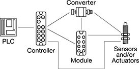
Create a system of sensors and actuators that you can remotely update, view measurements from, and receive error messages in real time. IO-Link systems minimize downtime by locating issues such as cut cables or dirty sensors quickly. They send only digital signals to your PLC, regardless of whether your sensors and actuators send digital or analog signals. Because these systems send digital signals, they’re more reliable and less prone to data error and signal loss than analog signals. It also means you don't have to use expensive shielded cables since they resist EMI.
When retrofitting an existing system, you'll need to make sure your PLC can incorporate IO-Link. Check with your PLC manufacturer—most have hardware that allows you to upgrade your PLC to run IO-Link.
Note: Sockets may have extra holes on their face that are not used.
Modules
 |  |
Surface Mount | DIN-Rail Mount |
Modules communicate between your sensors and actuators and your PLC. They are required. Setting memory automatically stores your settings and restores them once your device is back online. This eliminates needing to program a device again when you replace or fix it.
Surface Mount—Surface mount modules let you mount modules on equipment such as tanks and conveyors. By mounting them on your equipment, you save space in your control cabinet. They use M12 connectors.
DIN-Rail Mount—DIN-rail mount modules are designed to mount inside your control cabinet, so you can access all your process control devices in a central location. They include RJ45 Ethernet ports to support JSON and MQTT IoT (Internet of Things) protocols, allowing you to link the system directly to your web server to upload information to the Cloud. Connect these ports with RJ45 cords.
IP66 Enclosure Rating—IP66 rated components withstand washdowns.
IP67 Enclosure Rating—IP67 rated components can be temporarily submerged in water.
IP69K Enclosure Rating—IP69K rated components hold up to high-pressure and high-temperature washdowns.
Enclosure Rating—IP rated components block out dust and withstand some water, so they do not require an enclosure. Ports that are unused must be capped to maintain their rating.
Input | Output | |||||||||||||||||
|---|---|---|---|---|---|---|---|---|---|---|---|---|---|---|---|---|---|---|
Communication Protocol | No. of Device Ports | Total No. of RJ45 Connections | Total No. of M12 Connections | Type | Signal | Voltage, V DC | No. of | Type | Signal | Voltage, V DC | Current, mA, amp | No. of | Operating Voltage, V DC | Certification | Each | |||
Surface Mount | ||||||||||||||||||
IP66, IP67 | ||||||||||||||||||
| IO-Link, EtherNet/IP | 4 | — | 7 | Digital | PNP | 0 to 30 | 8 | Digital | PNP | 30 | 0.3 | 4 | 20 to 30 | UL Listed, C-UL Listed, CE Marked | 7585N13 | 0000000 | ||
| IO-Link, EtherNet/IP | 8 | — | 11 | Digital | PNP | 0 to 30 | 16 | Digital | PNP | 30 | 0.3 | 8 | 20 to 30 | UL Listed, C-UL Listed, CE Marked | 7585N14 | 000000 | ||
| IO-Link, Profinet | 4 | — | 7 | Digital | PNP | 0 to 30 | 8 | Digital | PNP | 30 | 0.3 | 4 | 20 to 30 | UL Listed, C-UL Listed, CE Marked | 7585N11 | 000000 | ||
| IO-Link, Profinet | 8 | — | 11 | Digital | PNP | 0 to 30 | 16 | Digital | PNP | 30 | 0.3 | 8 | 20 to 30 | UL Listed, C-UL Listed, CE Marked | 7585N12 | 000000 | ||
IP66, IP67, IP69K | ||||||||||||||||||
| IO-Link, EtherNet/IP | 4 | — | 7 | Digital | PNP | 0 to 30 | 8 | Digital | PNP | 30 | 0.3 | 4 | 20 to 30 | UL Listed, C-UL Listed, CE Marked | 7585N19 | 000000 | ||
| IO-Link, EtherNet/IP | 8 | — | 11 | Digital | PNP | 0 to 30 | 16 | Digital | PNP | 30 | 0.3 | 8 | 20 to 30 | UL Listed, C-UL Listed, CE Marked | 7585N21 | 000000 | ||
| IO-Link, Profinet | 4 | — | 7 | Digital | PNP | 0 to 30 | 8 | Digital | PNP | 30 | 0.3 | 4 | 20 to 30 | UL Listed, C-UL Listed, CE Marked | 7585N17 | 000000 | ||
| IO-Link, Profinet | 8 | — | 11 | Digital | PNP | 0 to 30 | 16 | Digital | PNP | 30 | 0.3 | 8 | 20 to 30 | UL Listed, C-UL Listed, CE Marked | 7585N18 | 000000 | ||
DIN-Rail Mount | ||||||||||||||||||
IP20 | ||||||||||||||||||
| IO-Link, EtherNet/IP | 8 | 3 | — | Digital | PNP | 0 to 30 | 8 | Digital | PNP | 30 | 0.3 | 8 | 20 to 30 | UL Listed, C-UL Listed, CE Marked | 7585N15 | 000000 | ||
| IO-Link, Profinet | 8 | 3 | — | Digital | PNP | 0 to 30 | 8 | Digital | PNP | 30 | 0.3 | 8 | 20 to 30 | UL Listed, C-UL Listed, CE Marked | 7585N16 | 000000 | ||
Expansion Modules
 |
Expansion modules increase the number of inputs and outputs in your IO-Link system, so you can add more sensors and actuators to your network. Connect multiple devices to each expansion module using M12 connectors, without needing to wire your devices inside a control cabinet. They transmit signals from multiple devices with a single cord. Expansion modules are optional, but when used, they must connect to a controller. Mount them on your equipment to save space in your control cabinet.
IP65 Enclosure Rating—IP65 rated components can be rinsed.
IP67 Enclosure Rating—IP67 rated components can be temporarily submerged in water.
IP69K Enclosure Rating—IP69K rated components hold up to high-pressure and high-temperature washdowns.
Enclosure Rating—IP rated components block out dust and withstand some water, so they do not require an enclosure. Ports that are unused must be capped to maintain their rating.
Input | Output | ||||||||||||||||
|---|---|---|---|---|---|---|---|---|---|---|---|---|---|---|---|---|---|
Expansion Module Type | Communication Protocol | No. of Device Ports | Total No. of M12 Connections | Type | Signal | Voltage, V DC | No. of | Type | Signal | Current, mA, amp | No. of | Operating Voltage, V DC | Certification | Each | |||
Surface Mount | |||||||||||||||||
IP65, IP67 | |||||||||||||||||
| Input | IO-Link | 6 | 7 | Digital | PNP | 16 to 30 | 12 | — | — | — | — | 18 to 30 | UL Listed, C-UL Listed, CE Marked | 7603N11 | 0000000 | ||
| Input | IO-Link | 10 | 11 | Digital | PNP | 16 to 30 | 20 | — | — | — | — | 18 to 30 | UL Listed, C-UL Listed, CE Marked | 7603N12 | 000000 | ||
| Input, Output | IO-Link | 8 | 10 | Digital | PNP | 18 to 30 | 16 | Digital | PNP | 3.6 | 16 | 18 to 30 | CE Marked | 7603N15 | 000000 | ||
| Output | IO-Link | 6 | 8 | — | — | — | — | Digital | PNP | 3.6 | 12 | 18 to 30 | UL Listed, C-UL Listed, CE Marked | 7603N13 | 000000 | ||
| Output | IO-Link | 10 | 12 | — | — | — | — | Digital | PNP | 3.6 | 20 | 18 to 30 | UL Listed, C-UL Listed, CE Marked | 7603N14 | 000000 | ||
IP65, IP67, IP69K | |||||||||||||||||
| Input | IO-Link | 6 | 7 | Digital | PNP | 16 to 30 | 12 | — | — | — | — | 18 to 30 | UL Listed, C-UL Listed, CE Marked | 7603N16 | 000000 | ||
| Input | IO-Link | 10 | 11 | Digital | PNP | 16 to 30 | 20 | — | — | — | — | 18 to 30 | UL Listed, C-UL Listed, CE Marked | 7603N17 | 000000 | ||
| Input, Output | IO-Link | 8 | 10 | Digital | PNP | 18 to 30 | 16 | Digital | PNP | 3.6 | 16 | 18 to 30 | CE Marked | 7603N21 | 000000 | ||
| Output | IO-Link | 6 | 8 | — | — | — | — | Digital | PNP | 3.6 | 12 | 18 to 30 | UL Listed, C-UL Listed, CE Marked | 7603N18 | 000000 | ||
| Output | IO-Link | 10 | 12 | — | — | — | — | Digital | PNP | 3.6 | 20 | 18 to 30 | UL Listed, C-UL Listed, CE Marked | 7603N19 | 000000 | ||
Converters
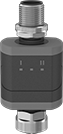 |
Converters translate analog signals to digital signals, making sensors and actuators IO-Link compatible. They are required to connect analog components to controllers and modules.
IP67 Enclosure Rating—IP67 rated components can be temporarily submerged in water.
Input | Output | |||||||||||||
|---|---|---|---|---|---|---|---|---|---|---|---|---|---|---|
Signal Converter Type | Total No. of M12 Connections | Signal Type | Digital Input Signal Type | Analog Input Signal Type | No. of | Signal Type | Digital Output Signal Type | Analog Output Signal Type | No. of | Certification | Each | |||
M12 Plug In | ||||||||||||||
Washdown (IP67) | ||||||||||||||
| Analog to Digital | 2 | Analog | — | 0 to 10V DC | 2 | Digital | PNP | — | 1 | UL Listed, C-UL Listed, CE Marked | 7603N52 | 0000000 | ||
| Analog to Digital to Analog | 2 | Analog | — | 4 to 20 mA | 1 | Digital, Analog | PNP | 4 to 20 mA | 2 | UL Listed, C-UL Listed, CE Marked | 7603N51 | 000000 | ||
| Digital to Analog | 2 | Digital | PNP | — | 1 | Analog | — | 4 to 20 mA | 2 | UL Listed, C-UL Listed, CE Marked | 7603N54 | 000000 | ||
| Digital to Analog | 2 | Digital | PNP | — | 1 | Analog | — | 0 to 10V DC | 2 | UL Listed, C-UL Listed, CE Marked | 7603N53 | 000000 | ||
Caps
 |
For Plugs |
 |
For Sockets |
For Thread | ||||||||
|---|---|---|---|---|---|---|---|---|
Size | Location | Material | Temp. Range, ° F | Includes | Each | |||
For Plugs, For Receptacles | ||||||||
| M12 | External | Anodized Aluminum | 0 to 220 | Lanyard | 6897K73 | 000000 | ||
| M12 | External | Stainless Steel | 0 to 220 | Lanyard | 6897K75 | 00000 | ||
For Receptacles, For Sockets | ||||||||
| M12 | Internal | Anodized Aluminum | 0 to 220 | — | 6897K74 | 00000 | ||
| M12 | Internal | Stainless Steel | 0 to 220 | Lanyard | 6897K59 | 00000 | ||
Handheld IO-Link Programmers
 |
 |
3-Pole M8 |
 |
4-Pole M8 |
 |
5-Pole M12 |
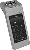
Configure any of your IO-Link devices—from sensors to switches—without a PC, outlet, or separate software. Use these programmers to set parameters, check the quality of runs, clone settings for other devices, and more. Whether you’re setting up a device for the first time or adjusting settings, the easy-to-use touchscreen makes for a smooth experience. Since these programmers are powered by a battery and small enough to carry, you can bring them wherever you need.
As soon as you connect your device, these programmers download its IO Device Description (IODD) file. This means you won’t need to manually input device details, saving you time to jump right into programming. Internal storage keeps IODD files and custom settings on hand for you. If you need extra space, insert a microSD card (not included) into these programmers before turning on the connected device.
Plug devices with M8 or M12 connections directly into the sockets on these programmers. If your device has wire leads, use the included adapter.
Connection Type | Internal Memory Size, GB | Data Connection | Features | Enclosure Rating | Battery Type | Includes | Certification | Each | ||
|---|---|---|---|---|---|---|---|---|---|---|
| A-Code, 3-Pole M8 Plug In A-Code, 4 -Pole M8 Plug In A-Code, 5-Pole M12 Plug In | 16 | Wi-Fi microSD Card | LED Status Indicator | IP30 | Rechargeable | M12 to 4 Hook Adapter (1 1/2 ft. Lg) USB Charging Cord (1 1/2 ft. Lg) | CE Marked | 6457N11 | 000000000 |
