


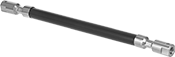
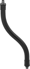
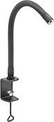
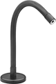
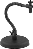
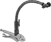
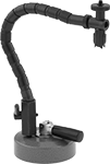
Bend-and-Stay Positioning Arms
Stronger and with greater load capacities than gooseneck-style positioning arms, these arms keep their shape even when moving or when exposed to vibration. They’re often used in robotics and conveyor applications when frequent repositioning isn’t required.
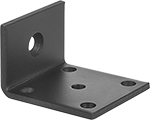
All accessories include the necessary hardware for attaching them to arms.
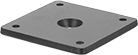
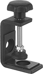
Clamp-on bases have two arm attachment locations. Place arms straight or at a right angle from the clamping screw. Clamp-on bases with a rubber V-block can be mounted to rounded surfaces such as pipe and railings.
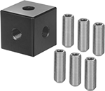
Attach up to five arms to your base with multi-arm adapters.
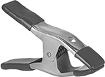
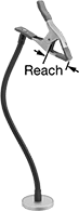
Spring clamps with three attaching end mounting holes can be mounted parallel or perpendicular to your positioning arm. Spring clamps with a 4 1/2" reach clamp further into a workpiece than other spring clamps.
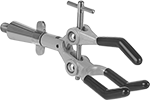
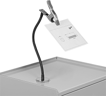
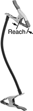
Three-finger clamps have bent fingers to hold workpieces that are hard to grip, such as beakers, flashlights, and webcams. A rotating position lock lets you rotate these clamps on your positioning arm. Secure clamps in place with the included locknut.
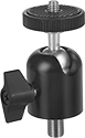
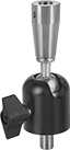
Ball-and-socket adapters and ball-and-socket connectors allow 360° rotation and up to 90° tilt. A locking knob keeps them in place.
Parallel brackets grip the ends of flat items.
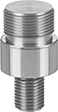
Threaded studs convert the threaded hole on your positioning arm.
Thread adapters convert the thread size and type on your positioning arm.
Secure items to attaching-end mounting pads with glue, hook and loop, screws, or other fasteners.
Base | Attaching End | |||||||||||||
|---|---|---|---|---|---|---|---|---|---|---|---|---|---|---|
| Max. Projection | Dia. | Max. Load Cap., lbs. | Material | Color | Mount Type | Mounting Thread Size | Mounting Hole Thread Type | Mounting Fasteners Included | Mount Type | Mounting Thread Size | Mounting Thread Type | Mounting Fasteners Included | Each | |
| 6" | 5/8" | 20 | Vinyl-Coated Copper | Black | Threaded Hole | 3/8"-24 | UNF | No | Threaded Hole | 3/8"-24 | UNF | No | 00000000 | 000000 |
| 9" | 5/8" | 7 | Vinyl-Coated Copper | Black | Threaded Hole | 3/8"-24 | UNF | No | Threaded Hole | 3/8"-24 | UNF | No | 00000000 | 00000 |
| 12" | 5/8" | 5 | Vinyl-Coated Copper | Black | Threaded Hole | 3/8"-24 | UNF | No | Threaded Hole | 3/8"-24 | UNF | No | 00000000 | 00000 |
| 18" | 5/8" | 3 | Vinyl-Coated Copper | Black | Threaded Hole | 3/8"-24 | UNF | No | Threaded Hole | 3/8"-24 | UNF | No | 00000000 | 00000 |
| 24" | 5/8" | 2.5 | Vinyl-Coated Copper | Black | Threaded Hole | 3/8"-24 | UNF | No | Threaded Hole | 3/8"-24 | UNF | No | 00000000 | 00000 |
| 30" | 5/8" | 2 | Vinyl-Coated Copper | Black | Threaded Hole | 3/8"-24 | UNF | No | Threaded Hole | 3/8"-24 | UNF | No | 00000000 | 00000 |
| 36" | 5/8" | 0.5 | Vinyl-Coated Copper | Black | Threaded Hole | 3/8"-24 | UNF | No | Threaded Hole | 3/8"-24 | UNF | No | 00000000 | 00000 |
Arm | ||||||||||
|---|---|---|---|---|---|---|---|---|---|---|
| Wd. | Lg. | Thick. | Max. Load Cap., lbs. | Material | Color | Surface Mounting Fasteners Included | Mount Type | Mounting Fasteners Included | Each | |
| 3" | 3" | 1/4" | 20 | Powder-Coated Steel | Black | Yes | Screw On | Yes | 00000000 | 000000 |
Arm | ||||||||||
|---|---|---|---|---|---|---|---|---|---|---|
| Wd. | Lg. | Thick. | Max. Load Cap., lbs. | Material | Color | Surface Mounting Fasteners Included | Mount Type | Mounting Fasteners Included | Each | |
| 3" | 3" | 2" | 20 | Powder-Coated Steel | Black | Yes | Screw On | Yes | 00000000 | 000000 |
For Max. Mounting Surface | Arm | |||||||||||
|---|---|---|---|---|---|---|---|---|---|---|---|---|
| Wd. | Lg. | Thick. | Dia. | Max. Load Cap., lbs. | Material | Color | Mount Type | Mounting Fasteners Included | Features | Includes | Each | |
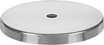
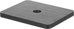
| 1 1/4" | 5 1/2" | 1 5/8" | __ | 20 | Powder-Coated Steel | Black | Screw On | Yes | Padded Base Clamp | __ | 00000000 | 000000 |
| 1 7/8" | 8 1/4" | 2 5/8" | 2" | 20 | Powder-Coated Steel | Black | Screw On | Yes | Padded Base Clamp, Ratchet Handle | Rubber V-Block | 00000000 | 00000 |
Arm | |||||||
|---|---|---|---|---|---|---|---|
| Dia. | Thick. | Max. Pull, lbs. | Case Material | Mount Type | Mounting Fasteners Included | Each | |
| 4 7/8" | 1/2" | 200 | Nickel-Plated Steel | Screw On | Yes | 00000000 | 000000 |

Arm | |||||||
|---|---|---|---|---|---|---|---|
| Dia. | Max. Load Cap., lbs. | Material | Color | Mount Type | Mounting Fasteners Included | Each | |
| 9" | 20 | Powder-Coated Steel | Black | Screw On | Yes | 00000000 | 000000 |
Base | |||||||||||
|---|---|---|---|---|---|---|---|---|---|---|---|
| Wd. | Lg. | Thick. | Max. Load Cap., lbs. | Material | Color | Mount Type | Mounting Thread Size | Mounting Hole Thread Type | Includes | Each | |
| 1 1/4" | 1 1/4" | 1 1/4" | 5 | Anodized Aluminum | Black | Threaded Hole, Threaded Stud | 3/8"-24 | UNF | Six 3/8"-24 Threaded Studs | 00000000 | 000000 |
Arm Attaching End | |||||||||||||||
|---|---|---|---|---|---|---|---|---|---|---|---|---|---|---|---|
| Rotation Range of Motion | Max. Opening | Reach | Jaw Wd. | Lg. | Max. Load Cap., lbs. | Material | Color | Mount Type | Mounting Fasteners Included | Mounting Thread Size | Mounting Thread Type | Number of Mounting Holes | Features | Each | |
| 360° | 0.31" | 0.59" | 0.13" | 4 1/2" | 1 | Nickel-Plated Steel | __ | Threaded Stud | __ | 3/8"-24 | UNF | __ | Locknut | 00000000 | 000000 |
| __ | 2" | 2" | 1" | 6 1/4" | 10 | Chrome-Plated Steel | __ | Screw On | Yes | __ | __ | 1 | Vinyl Grips | 00000000 | 00000 |
| __ | 3" | 3 3/4" | 6" | 8" | 10 | Plastic | Black | Screw On | Yes | __ | __ | 3 | __ | 00000000 | 00000 |
| __ | 3" | 4 1/2" | 3/8" | 8 1/2" | 10 | Plastic | Black | Screw On | Yes | __ | __ | 3 | __ | 00000000 | 00000 |
Arm Attaching End | ||||||||||||
|---|---|---|---|---|---|---|---|---|---|---|---|---|
| Rotation Range of Motion | Max. Opening | Reach | Lg. | Max. Load Cap., lbs. | Material | Color | Mount Type | Mounting Thread Size | Mounting Thread Type | Features | Each | |
| 360° | 3 5/8" | 2 1/2" | 6 3/4" | 5 | Powder-Coated Aluminum | Gray | Threaded Stud | 3/8"-24 | UNF | Locknut, Vinyl-Coated Fingers | 00000000 | 000000 |
Attaching End | Arm Attaching End | |||||||||||||
|---|---|---|---|---|---|---|---|---|---|---|---|---|---|---|
| Lg. | Rotation Range of Motion | Tilt Range of Motion | Mount Type | Mounting Thread Size | Mounting Thread Type | Max. Load Cap., lbs. | Body Material | Color | Mount Type | Mounting Thread Size | Mounting Thread Type | Features | Each | |
| 2 1/2" | 360° | 90° | Threaded Stud | 1/4"-20 | UNC | 6 | Anodized Aluminum | Black | Threaded Stud | 3/8"-24 | UNF | Locking Knob, Rubber-Padded Camera Seat | 00000000 | 000000 |
Attaching End | Arm Attaching End | ||||||||||||||
|---|---|---|---|---|---|---|---|---|---|---|---|---|---|---|---|
| Lg. | Rotation Range of Motion | Tilt Range of Motion | Mount Type | Mounting Fasteners Included | Mounting Thread Size | Mounting Thread Type | Max. Load Cap., lbs. | Material | Color | Mount Type | Mounting Thread Size | Mounting Thread Type | Features | Each | |
| 3 7/8" | 360° | 90° | Threaded Hole | Yes | 3/8"-24 | UNF | 6 | Anodized Aluminum | Black | Threaded Stud | 3/8"-24 | UNF | Locking Knob | 00000000 | 000000 |
Arm Attaching End | |||||||||
|---|---|---|---|---|---|---|---|---|---|
| For Device Ht. | For Min. Device Wd. | Max. Load Cap., lbs. | Material | Color | Mount Type | Mounting Fasteners Included | Features | Each | |
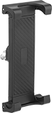
| 5 1/2"-11 1/2" | 2" | 2 | Plastic | Black | Screw On | Yes | Adjustable Arms | 00000000 | 000000 |
Attaching End | ||||||
|---|---|---|---|---|---|---|
| Length | Material | Mount Type | Mounting Thread Size | Mounting Thread Type | Each | |
| 1" | 303 Stainless Steel | Threaded Stud | 3/8"-24 | UNF | 00000000 | 00000 |
Threaded
Hole
Threaded
Stud
Attaching End | Arm Attaching End | |||||||||
|---|---|---|---|---|---|---|---|---|---|---|
| Lg. | Mounting Thread Size | Mounting Thread Pitch, mm | Mounting Thread Type | Mounting Fasteners Included | Material | Mount Type | Mounting Thread Size | Mounting Thread Type | Each | |
Threaded Hole | ||||||||||
| 1 3/4" | 1/4"-20 | __ | UNC | Yes | 303 Stainless Steel | Threaded Stud | 3/8"-24 | UNF | 00000000 | 000000 |
| 1 3/4" | 8-32 | __ | UNC | Yes | 303 Stainless Steel | Threaded Stud | 3/8"-24 | UNF | 00000000 | 00000 |
| 1 3/4" | M8 | 1.25 | Metric | Yes | 303 Stainless Steel | Threaded Stud | 3/8"-24 | UNF | 00000000 | 00000 |
Threaded Stud | ||||||||||
| 1 5/16" | 5/8"-27 | __ | UNS | __ | 303 Stainless Steel | Threaded Stud | 3/8"-24 | UNF | 00000000 | 0000 |
Attaching End | Arm Attaching End | |||||||
|---|---|---|---|---|---|---|---|---|
| Mount Type | Mounting Fasteners Included | Lg. | Material | Mount Type | Mounting Thread Size | Mounting Thread Type | Each | |
| Screw On | Yes | 2 1/2" | 303 Stainless Steel | Threaded Stud | 3/8"-24 | UNF | 00000000 | 000000 |
Arm Attaching End | |||||||||
|---|---|---|---|---|---|---|---|---|---|
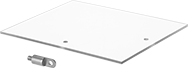
| Wd. | Lg. | Thick. | Material | Color | Mount Type | Mounting Fasteners Included | Includes | Each | |
| 10" | 12" | 1/4" | Plastic | Clear | Screw On | Yes | Right-Angle Thread Adapter | 00000000 | 000000 |

Arm Attaching End | ||||||||||||||
|---|---|---|---|---|---|---|---|---|---|---|---|---|---|---|
| Shape | Rotation Range of Motion | Tilt Range of Motion | Dia. | Wd. | Lg. | Mirror Material | Material | Color | Mount Type | Mounting Fasteners Included | Mounting Thread Size | Mounting Thread Type | Each | |
Convex | ||||||||||||||
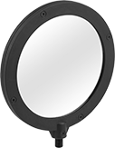
| Round | 360° | 30° | 6 1/4" | __ | __ | Glass | Powder-Coated Steel | Black | Threaded Stud | __ | 3/8"-24 | UNF | 00000000 | 000000 |
| Round | 360° | 30° | 8 1/2" | __ | __ | Glass | Powder-Coated Steel | Black | Screw On | Yes | __ | __ | 00000000 | 00000 |
Flat | ||||||||||||||
| Rectangle | 360° | 30° | __ | 5 1/2" | 7 1/2" | Glass | Powder-Coated Steel | Black | Threaded Stud | __ | 3/8"-24 | UNF | 00000000 | 00000 |
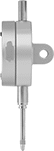
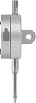
Any-Which-Way Positioning Arms
Bend these arms to hold small equipment such as lights and microphones in almost any position.
Use threaded stud and threadlocker to convert a threaded hole into a threaded stud.
| Max. Projection | Attaching End Mount. Thread Size | Base Mount. Thread Size | Max. Load Capacity, lbs. | Material | Color | Includes | Each | |
Threaded Hole/Threaded Stud Attaching End | ||||||||
|---|---|---|---|---|---|---|---|---|
| 6" | 1/4"-20 | 1/4"-20 | 4 | Vinyl-Coated Steel | Black | Two 1/4"-20 Threaded Studs, Threadlocker | 00000000 | 000000 |
| 9" | 1/4"-20 | 1/4"-20 | 3.5 | Vinyl-Coated Steel | Black | Two 1/4"-20 Threaded Studs, Threadlocker | 00000000 | 00000 |
| 12" | 1/4"-20 | 1/4"-20 | 3 | Vinyl-Coated Steel | Black | Two 1/4"-20 Threaded Studs, Threadlocker | 00000000 | 00000 |
| 15" | 1/4"-20 | 1/4"-20 | 2.5 | Vinyl-Coated Steel | Black | Two 1/4"-20 Threaded Studs, Threadlocker | 00000000 | 00000 |
| 18" | 1/4"-20 | 1/4"-20 | 2.5 | Vinyl-Coated Steel | Black | Two 1/4"-20 Threaded Studs, Threadlocker | 00000000 | 00000 |
| 24" | 1/4"-20 | 1/4"-20 | 1.5 | Vinyl-Coated Steel | Black | Two 1/4"-20 Threaded Studs, Threadlocker | 00000000 | 00000 |
| 30" | 1/4"-20 | 1/4"-20 | 0.8 | Vinyl-Coated Steel | Black | Two 1/4"-20 Threaded Studs, Threadlocker | 00000000 | 00000 |
| 36" | 1/4"-20 | 1/4"-20 | 0.6 | Vinyl-Coated Steel | Black | Two 1/4"-20 Threaded Studs, Threadlocker | 00000000 | 00000 |


| Max. Projection | Attaching End Mount. Thread Size | Attaching End Mount. Pipe Size | Base Mount. Thread Size | Base Mount. Pipe Size | Max. Load Capacity, lbs. | Material | Color | Each | |
Threaded Hole Attaching End | |||||||||
|---|---|---|---|---|---|---|---|---|---|
| 6" | 5/8"-27 | __ | 5/8"-27 | __ | 3 | Vinyl-Coated Steel | Black | 000000000 | 00000 |
| 13" | 5/8"-27 | __ | 5/8"-27 | __ | 1 | Vinyl-Coated Steel | Black | 000000000 | 00000 |
| 19" | 5/8"-27 | __ | 5/8"-27 | __ | 1 | Vinyl-Coated Steel | Black | 000000000 | 00000 |
Threaded Stud Attaching End | |||||||||
| 9" | __ | 1/8 | __ | 1/8 | 2 | Vinyl-Coated Steel | Black | 000000000 | 0000 |
| 15" | __ | 1/8 | __ | 1/8 | 1 | Vinyl-Coated Steel | Black | 000000000 | 0000 |
| 24" | __ | 1/8 | __ | 1/8 | 1 | Vinyl-Coated Steel | Black | 000000000 | 00000 |
Base with
Plate Attaching End
Attaching End | Base | |||||||||||||
|---|---|---|---|---|---|---|---|---|---|---|---|---|---|---|
| Max. Projection | Plate Lg. | Plate Wd. | No. of Mount. Holes | Mount. Hole Dia. | Mount. Fasteners Included | No. of Mount. Holes | Mount. Hole Dia. | Lg. | Wd. | Max. Load Capacity, lbs. | Material | Color | Each | |
| 14" | 2" | 1 7/8" | 8 | 3/16" | No | 3 | 13/64" | 2" | 3" | 5 | Vinyl-Coated Steel | Black | 000000 | 000000 |
Hole/Threaded
Stud Attaching End
Use threaded stud and threadlocker to convert a threaded hole into a threaded stud.
Base | ||||||||||||
|---|---|---|---|---|---|---|---|---|---|---|---|---|
| Max. Projection | Attaching End Mount. Thread Size | Mount. Fasteners Included | No. of Mount. Holes | Mount. Hole Dia. | Lg. | Wd. | Max. Load Capacity, lbs. | Material | Color | Includes | Each | |
| 9" | 1/4"-20 | No | 2 | 0.275" | 2" | 1" | 3.5 | Vinyl-Coated Steel | Black | One 1/4"-20 Threaded Stud, Threadlocker | 00000000 | 000000 |
| 9" | 3/8"-16 | Yes | 2 | 0.275" | 2" | 1" | 3 | Vinyl-Coated Steel | Black | One 3/8"-16 Threaded Stud, Threadlocker | 00000000 | 00000 |
| 16" | 1/4"-20 | No | 2 | 0.275" | 2" | 1" | 2.5 | Vinyl-Coated Steel | Black | One 1/4"-20 Threaded Stud, Threadlocker | 00000000 | 00000 |
| 16" | 3/8"-16 | No | 2 | 0.275" | 2" | 1" | 2.5 | Vinyl-Coated Steel | Black | One 3/8"-16 Threaded Stud, Threadlocker | 00000000 | 00000 |
| 24" | 1/4"-20 | No | 2 | 0.275" | 2" | 1" | 1.5 | Vinyl-Coated Steel | Black | One 1/4"-20 Threaded Stud, Threadlocker | 00000000 | 00000 |
| 24" | 3/8"-16 | No | 2 | 0.275" | 2" | 1" | 1.5 | Vinyl-Coated Steel | Black | One 3/8"-16 Threaded Stud, Threadlocker | 00000000 | 00000 |
Arms with padded base clamp have plastic pads that protect mounting surfaces from marring.
Where included, use threaded stud and threadlocker to convert a threaded hole into a threaded stud.
Base | |||||||||||
|---|---|---|---|---|---|---|---|---|---|---|---|
| Max. Projection | Attaching End Mount. Thread Size | Lg. | Wd. | For Max. Mount. Surface Thick. | Max. Load Capacity, lbs. | Material | Color | Includes | Features | Each | |
Threaded Hole Attaching End | |||||||||||
| 16" | 3/8"-16 | 2" | 2" | 2" | 2.5 | Vinyl-Coated Steel | Black | __ | Padded Base Clamp | 00000000 | 000000 |
| 24" | 3/8"-16 | 2" | 2" | 2" | 1.5 | Vinyl-Coated Steel | Black | __ | Padded Base Clamp | 00000000 | 00000 |
Threaded Hole/Threaded Stud Attaching End | |||||||||||
| 9" | 1/4"-20 | 2 7/8" | 2" | 2" | 3.5 | Vinyl-Coated Steel | Black | One 1/4"-20 Threaded Stud, Threadlocker | __ | 00000000 | 00000 |
| 9" | 3/8"-16 | 2" | 1 5/8" | 2" | 3 | Vinyl-Coated Steel | Black | One 3/8"-16 Threaded Stud, Threadlocker | Padded Base Clamp | 00000000 | 00000 |
| 16" | 1/4"-20 | 2 7/8" | 2" | 2" | 2.5 | Vinyl-Coated Steel | Black | One 1/4"-20 Threaded Stud, Threadlocker | __ | 00000000 | 00000 |
| 24" | 1/4"-20 | 2 7/8" | 2" | 2" | 1.5 | Vinyl-Coated Steel | Black | One 1/4"-20 Threaded Stud, Threadlocker | __ | 00000000 | 00000 |
Where included, use threaded stud and threadlocker to convert a threaded hole into a threaded stud.
| Max. Projection | Attaching End Mount. Thread Size | Base Dia. | Max. Pull, lbs. | Max. Load Capacity, lbs. | Material | Color | Includes | Each | |
Threaded Hole Attaching End | |||||||||
|---|---|---|---|---|---|---|---|---|---|
| 16" | 3/8"-16 | 3" | 100 | 2.5 | Vinyl-Coated Steel | Black | __ | 00000000 | 000000 |
| 25" | 3/8"-16 | 3" | 100 | 1.5 | Vinyl-Coated Steel | Black | __ | 00000000 | 00000 |
Threaded Hole/Threaded Stud Attaching End | |||||||||
| 9" | 1/4"-20 | 3 1/4" | 100 | 3.5 | Vinyl-Coated Steel | Black | One 1/4"-20 Threaded Stud, Threadlocker | 00000000 | 00000 |
| 9" | 3/8"-16 | 3" | 100 | 3 | Vinyl-Coated Steel | Black | One 3/8"-16 Threaded Stud, Threadlocker | 00000000 | 00000 |
| 16" | 1/4"-20 | 3 1/4" | 100 | 2.5 | Vinyl-Coated Steel | Black | One 1/4"-20 Threaded Stud, Threadlocker | 00000000 | 00000 |
| 24" | 1/4"-20 | 3 1/4" | 100 | 1.5 | Vinyl-Coated Steel | Black | One 1/4"-20 Threaded Stud, Threadlocker | 00000000 | 00000 |
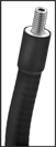
Spring Clamps with Flexible Arm
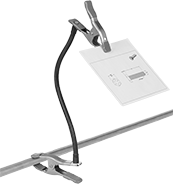
Attached to an arm you can flex into position, these clamps hold objects such as a flashlight, tool, or instructions. Squeeze the handles to open the clamp; release and the spring holds it tightly in place.
Magnetic-mount clamp attaches to steel surfaces.
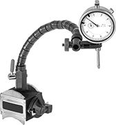
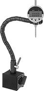
Flexible-Arm Magnetic-Base Indicator Holders
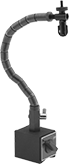
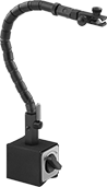
and Fine-Adjustment
Clamp
Adjust the flexible arm to nearly any position. These holders have a ball-and-socket segmented arm that locks in place with a lever. The magnetic base has a release switch for easy setups.
Holders with V-grooved base can be mounted on both curved and flat surfaces.
Holders with fine-adjustment base or clamp give you more precise control over positioning.
Indicator Holders | ||||||||||||||
|---|---|---|---|---|---|---|---|---|---|---|---|---|---|---|
Base | Arm | Replacement Arms | ||||||||||||
| For Mounting Stem Dia. | Type | Lg. | Wd. | Ht. | Thread Size | Thread Pitch, mm | Material | Magnetic Pull, lbs. | Lg. | Dia. | Each | Each | ||
Dovetail and Stem Mount | ||||||||||||||
Magnetic-Release Switch | ||||||||||||||
| 3/8" | V-Grooved | 2 1/2" | 2" | 2 1/8" | M8 | 1.25 | Steel | 125 | 12" | 0.625" | 00000000 | 000000 | 00000000 | 000000 |
Fine-Adjustment Clamp, Magnetic-Release Switch | ||||||||||||||
| 3/8" | V-Grooved | 2" | 2 1/2" | 2 5/8" | 5/16''-18 | __ | Steel | 90 | 15 1/4" | 0.625" | 00000000 | 000000 | 00000000 | 00000 |
Stem Mount | ||||||||||||||
Magnetic-Release Switch | ||||||||||||||
| 5/32"-1/2" | V-Grooved | 2 1/2" | 2" | 2 1/4" | M8 | 1.25 | Steel | 180 | 12 1/2" | 0.63" | 0000000 | 00000 | 0000000 | 00000 |
Fine-Adjustment Base, Magnetic-Release Switch | ||||||||||||||
| 1/8"-1/2" | Flat | 2" | 1 5/8" | 2" | __ | __ | Steel | 65 | 14" | 0.625" | 00000000 | 000000 | 00000000 | 000000 |
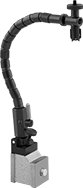
Flexible-Arm Magnetic-Base Indicator Holders for Uneven Surfaces
A flexible ball-and-socket segmented arm adjusts to nearly any position and locks in place with a lever. The base is comprised of adjustable magnetic pins which allow it to conform to any shape and grip most metal surfaces. It has a magnetic-release switch for easy setups.
Base | Arm | ||||||||||||
|---|---|---|---|---|---|---|---|---|---|---|---|---|---|
| For Mounting Stem Dia. | Lg. | Wd. | Ht. | Thread Size | Thread Pitch, mm | Material | Magnetic Pull, lbs. | Lg. | Dia. | Material | Features | Each | |
Stem Mount | |||||||||||||
| 5/64"-1/2" | 1 15/16" | 1 5/8" | 2 7/8" | M8 | 1.25 | Cast Aluminum | 120 | 12 1/2" | 0.47" | Steel | Magnetic-Release Switch | 0000000 | 0000000 |
Economy Flexible-Arm Weighted-Base Indicator Holders
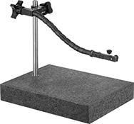
Adjust the flexible ball-and-socket segmented arm to nearly any position and lock in place. A heavy base adds stability.
Holders with a granite base have an extremely tight flatness tolerance. Their flatness gives you an accurate reference for inspection work and lets you move workpieces in and out smoothly. These holders have a fine-adjustment clamp to position indicators at precise angles.
Base | Upright Post | Arm | |||||||||||
|---|---|---|---|---|---|---|---|---|---|---|---|---|---|
| For Mounting Stem Dia. | Dia. | Lg. | Wd. | Ht. | Thread Size | Material | Dia. | Ht. | Lg. | Dia. | Features | Each | |
Dovetail and Stem Mount | |||||||||||||
| 5/8" | __ | 9" | 12" | 2" | 5/16''-24 | Granite | 5/8" | 12" | 12" | 0.625" | Fine-Adjustment Clamp | 0000000 | 0000000 |
| 5/8" | __ | 12" | 18" | 3" | 5/16''-24 | Granite | 5/8" | 12" | 15" | 0.625" | Fine-Adjustment Clamp | 0000000 | 000000 |
Stem Mount | |||||||||||||
| 1/8"-1/2" | 6" | __ | __ | 15/16" | 5/16''-18 | Cast Iron | __ | __ | 13" | 0.625" | __ | 0000000 | 000000 |
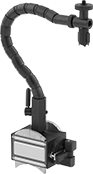
Flexible-Arm Clamp-On Indicator Holders
Vise-grip locking pliers clamp this holder to most thin, flat surfaces, and the flexible arm lets you position your indicator around obstructions. Lock the arm in place with a lever.
Flexible-Arm Vacuum-Base Indicator Holders
Position the flexible ball-and-socket segmented arm around obstructions and lock in place with a lever. The vacuum base provides stability on granite plates and other nonmagnetic surfaces.
Base | Arm | ||||||||
|---|---|---|---|---|---|---|---|---|---|
| For Mounting Stem Dia. | Dia. | Ht. | Thread Size | Thread Pitch, mm | Material | Lg. | Dia. | Each | |
Stem Mount | |||||||||
| 1/8"-1/2" | 3.465" | 1.063" | M8 | 1.25 | Aluminum | 13" | 0.625" | 0000000 | 0000000 |
Economy Dial Plunger-Style Variance Indicators with Clamp-On Holder


Often used where space is tight or there’s not much of a surface for mounting, the clamp on these indicators fits where a weighted or magnetic base can’t. The clamp also gives you the option to directly mount these indicators to a machine or the piece you’re measuring. With the ball-and-socket segmented arm, you can adjust the indicator to nearly any position to keep it from obstructing what you're measuring. Pull the lever to lock the arm in place when you're done. To measure objects, these indicators have a spring-loaded plunger that retracts and extends as the surface varies. It’s easy to see how much a measurement increases, since the dial is continuous and numbered clockwise around the face. Adjust the tolerance pointers to mark measurements that fall outside your limits.
Indicators with a plier clamp work on most thin, flat surfaces.
Indicators with a C-clamp apply less pressure than indicators with a plier clamp, so there’s less risk of damaging a workpiece.
Dial | Contact Point | Arm | ||||||||||||||
|---|---|---|---|---|---|---|---|---|---|---|---|---|---|---|---|---|
| Measuring Range | Measuring Increments | Accuracy | Industry Designation | Indicator Mount. Stem Dia. | Mount. Lug Hole Dia. | Dia. | Reading | Head Dia. | Lg. | Mount. Thread Size | Clamping Range | Dia. | Lg. | Flexibility | Each | |
Lug and Stem Mount | ||||||||||||||||
Plier Clamp | ||||||||||||||||
| 0.000"-1.000" | 0.001" | ±0.001" | AGD Group 1 | 3/8" | 1/4" | 2" | 0-100 | 0.197" | 0.236" | 4-48 | 0"-1 3/4" | 0.625" | 12" | Flexible | 0000000 | 000000 |
C-Clamp | ||||||||||||||||
| 0.000"-1.000" | 0.001" | ±0.001" | AGD Group 1 | 3/8" | 1/4" | 2" | 0-100 | 0.197" | 0.236" | 4-48 | 0"-6" | 0.625" | 12" | Flexible | 0000000 | 00000 |
Economy Dial Plunger-Style Variance Indicators
with Magnetic-Base Holder for Uneven Surfaces
With adjustable magnetic pins that conform to any shape, the base on these variance indicators mounts securely to uneven surfaces. The ball-and-socket arm is highly adjustable and locks in place with a lever, so you can hold them in almost any position. A spring-loaded plunger retracts and extends to measure objects. These indicators have a continuous dial numbered clockwise around the face, so it’s easy to see how much a dimension increases. Adjust the tolerance pointers to mark measurements that fall outside your limits. For quick dismounting, the base has a magnetic release switch.
Dial | Contact Point | Arm | ||||||||||||||
|---|---|---|---|---|---|---|---|---|---|---|---|---|---|---|---|---|
| Measuring Range | Measuring Increments | Accuracy | Industry Designation | Indicator Mounting Stem Dia. | Mounting Lug Hole Dia. | Dia. | Reading | Head Dia. | Lg. | Mounting Thread Size | Base Magnetic Pull, lbs. | Lg. | Dia. | Flexibility | Each | |
Lug and Stem Mount | ||||||||||||||||
| 0"-1" | 0.001" | ±0.001" | AGD Group 2 | 3/8" | 1/4" | 2" | 0-100 | 0.197" | 0.275" | 4-48 | 125 | 12" | 0.625" | Flexible | 0000000 | 000000 |
Economy Dial Plunger-Style Variance Indicators
with Flexible-Arm Magnetic-Base Holder
Measure in almost any position—these variance indicators have an adjustable ball-and-socket arm that locks in place with a lever. With a magnetic V-grooved base, they mount securely to both flat and curved metal surfaces. A spring-loaded plunger retracts and extends to measure objects. These indicators have a continuous dial numbered clockwise around the face, so it’s easy to see how much a dimension increases. Adjust the tolerance pointers to mark measurements that fall outside your limits. For quick dismounting, the base has a magnetic release switch.
Dial | Contact Point | Arm | |||||||||||||
|---|---|---|---|---|---|---|---|---|---|---|---|---|---|---|---|
| Measuring Range | Measuring Increments | Accuracy | Industry Designation | Indicator Mounting Stem Dia. | Mounting Lug Hole Dia. | Dia. | Reading | Head Dia. | Lg. | Mounting Thread Size | Base Magnetic Pull, lbs. | Lg. | Dia. | Each | |
Lug and Stem Mount | |||||||||||||||
| 0"-1" | 0.001" | ±0.001" | AGD Group 2 | 3/8" | 1/4" | 2" | 0-100 | 0.197" | 0.275" | 4-48 | 80 | 12" | 0.375" | 0000000 | 000000 |
Economy Electronic Plunger-Style Variance Indicators
with Magnetic-Base Holder for Uneven Surfaces
With adjustable magnetic pins that conform to any shape, the base on these variance indicators mounts securely to uneven surfaces. The ball-and-socket arm is highly adjustable and locks in place with a lever, so it holds the indicator in almost any position. For quick dismounting, the base has a magnetic release switch.
A spring-loaded plunger extends and retracts to measure objects. The measurements are displayed on an LCD screen. Start measuring at any point by pressing the zero-set button. They have zero-position memory, also known as absolute (ABS) positioning, which retains the measuring position when the indicator is off.
All can send data to your computer using a USB cord (sold separately). They have SPC data output to wirelessly transfer your measurement data to your device with the push of a button. You'll need a data transmitter/receiver set (sold separately). Indicators with Bluetooth send measurement data to your device wire-free and without an additional device.
IP67-rated indicators seal out coolant, water, and dust, so you can take measurements in dirty machining environments.
Tolerance checking indicators inform you when an item falls outside your set measurements.
Contact Point | ||||||||||||||
|---|---|---|---|---|---|---|---|---|---|---|---|---|---|---|
| Measuring Range | Measuring Increments | Accuracy | Counting Direction | Industry Designation | Dial Dia. | Head Dia. | Lg. | Mount. Thread Size | Base Magnetic Pull, lbs. | Arm Lg. | Batteries Included | Features | Each | |
Lug and Stem Mount | ||||||||||||||
With SPC Data Output | ||||||||||||||
| 0"-1" 0mm-25mm | 0.0005" 0.01mm | ±0.0015" ±0.03 mm | Forward | AGD Group 2 | 2 3/16" | 0.197" | 0.354" | 4-48 | 125 | 12" | Yes | Magnetic Release Switch, Zero-Position Memory (ABS), Zero-Set Button | 0000000 | 0000000 |
Lug and Stem Mount—IP67 | ||||||||||||||
With SPC Data Output, Bluetooth Connection, and Charging Cord | ||||||||||||||
| 0"-1" 0mm-25mm | 0.00005" 0.001mm | ±0.00035" ±0.008 mm | Forward, Backward | AGD Group 2 | 2 3/16" | 0.197" | 0.315" | 4-48 | 125 | 12" | Yes | Magnetic Release Switch, Tolerance-Checking Go/No-Go Operation, Zero-Position Memory (ABS), Zero-Set Button | 0000000 | 000000 |
Economy Electronic Plunger-Style Variance
Indicators with Flexible-Arm Magnetic-Base Holder
Bend and flex the arm of the base to position your indicator—these holders have ball-and-socket segments that lock in place with a lever. The base is magnetic and has a V-groove on the bottom for a solid mount on flat and curved metal surfaces. Flip a switch to release the magnet.
A spring-loaded plunger extends and retracts from the indicator to take measurements. The measurements display on an easy-to-read LCD screen. Press the zero-set button to start measuring at any point. They have zero-position memory, also known as absolute (ABS) positioning, which retains the measuring position when the indicator is off.
All can send data to your computer using a USB cord (sold separately). They have SPC data output to wirelessly transfer your measurement data to your device with the push of a button. You'll need a data transmitter/receiver set (sold separately). Indicators with Bluetooth send measurement data to your device wire-free and without an additional device.
IP67-rated indicators seal out coolant, water, and dust, so you can take measurements in dirty machining environments.
Tolerance checking indicators inform you when an item falls outside your set measurements.
Contact Point | ||||||||||||||
|---|---|---|---|---|---|---|---|---|---|---|---|---|---|---|
| Measuring Range | Measuring Increments | Accuracy | Counting Direction | Industry Designation | Dial Dia. | Head Dia. | Lg. | Mount. Thread Size | Base Magnetic Pull, lbs. | Arm Lg. | Batteries Included | Features | Each | |
Lug and Stem Mount | ||||||||||||||
With SPC Data Output | ||||||||||||||
| 0"-1" 0mm-25mm | 0.0005" 0.01mm | ±0.0015" ±0.03 mm | Forward | AGD Group 2 | 2 3/16" | 0.197" | 0.354" | 4-48 | 125 | 12" | Yes | Magnetic Release Switch, Zero-Position Memory (ABS), Zero-Set Button | 0000000 | 000000 |
Lug and Stem Mount—IP67 | ||||||||||||||
With SPC Data Output, Bluetooth Connection, and Charging Cord | ||||||||||||||
| 0"-1" 0mm-25mm | 0.00005" 0.001mm | ±0.00035" ±0.008 mm | Forward, Backward | AGD Group 2 | 2 3/16" | 0.197" | 0.315" | 4-48 | 125 | 12" | Yes | Magnetic Release Switch, Tolerance-Checking Go/No-Go Operation, Zero-Position Memory (ABS), Zero-Set Button | 0000000 | 000000 |