


Filter by
Body Material
Wetted Parts Material
Maximum Temperature
Maximum Flow Rate
Fitting Connection

Fitting Material
Flow Measurement Type
Connects To
Maximum Switching Current @ Voltage
Maximum Pressure @ Temperature
Shape
Certification
DFARS Specialty Metals
Export Control Classification Number (ECCN)
Fixed-Set-Point Flow Switches
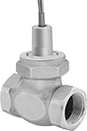 |
Style C |
Since they come factory set to a specific set point, these switches are easier to install than adjustable flow switches. As flowing liquid pushes an internal piston, the switch reads the position of the piston to measure the flow. When the piston passes the set point, the switch actuates. They’re accurate in any mounting position.
These switches are calibrated with and measure water accurately. They can also be used with other liquids by applying your liquid’s specific-gravity conversion factor to calculate the new set point.
Choose a fitting material that is compatible with the liquid you intend to run through your line.
Straight
|
Style C |
316 Stainless Steel Fitting and Bronze Fitting—Bronze and 316 stainless steel fittings resist impact better than plastic fittings.
SPDT—SPDT (single pole, double throw) switches can either turn one device from off to on (normally open) or from on to off (normally closed).
Conduit | |||||||||||||||||||||||||||||||||||||||||||||||||||||||||||||||||||||||||||||||||||||||||||||||||||
|---|---|---|---|---|---|---|---|---|---|---|---|---|---|---|---|---|---|---|---|---|---|---|---|---|---|---|---|---|---|---|---|---|---|---|---|---|---|---|---|---|---|---|---|---|---|---|---|---|---|---|---|---|---|---|---|---|---|---|---|---|---|---|---|---|---|---|---|---|---|---|---|---|---|---|---|---|---|---|---|---|---|---|---|---|---|---|---|---|---|---|---|---|---|---|---|---|---|---|---|
Style | Pipe Size | Thread Type | Gender | Set Point, gpm | Approx. Difference Between Set Point and Reset Point, gpm | Max. Pressure @ Temp. | Temp. Range, ° F | Max. Switching Current @ Voltage | Trade Size | Thread Type | Gender | End-to-End Lg. | Mounting Position | Each | |||||||||||||||||||||||||||||||||||||||||||||||||||||||||||||||||||||||||||||||||||||
Bronze Body with Bronze Fittings | |||||||||||||||||||||||||||||||||||||||||||||||||||||||||||||||||||||||||||||||||||||||||||||||||||
SPDT | |||||||||||||||||||||||||||||||||||||||||||||||||||||||||||||||||||||||||||||||||||||||||||||||||||
| C | 1 | NPT | Female | 0.5 | 0.075 | 400 psi @ 70° F | -20 to 300 | 400 mA @ 30V AC 170 mA @ 120V AC 80 mA @ 240V AC 300 mA @ 30V DC 130 mA @ 120V DC 60 mA @ 240V DC | 1/2 | NPT | Male | 3 1/4" | Any Angle | 6486T211 | 0000000 | ||||||||||||||||||||||||||||||||||||||||||||||||||||||||||||||||||||||||||||||||||||
| C | 1 | NPT | Female | 1 | 0.15 | 300 psi @ 70° F | -20 to 300 | 400 mA @ 30V AC 170 mA @ 120V AC 80 mA @ 240V AC 300 mA @ 30V DC 130 mA @ 120V DC 60 mA @ 240V DC | 1/2 | NPT | Male | 3 3/8" | Any Angle | 4553N11 | 000000 | ||||||||||||||||||||||||||||||||||||||||||||||||||||||||||||||||||||||||||||||||||||
| C | 1 | NPT | Female | 2 | 0.3 | 400 psi @ 70° F | -20 to 300 | 400 mA @ 30V AC 170 mA @ 120V AC 80 mA @ 240V AC 300 mA @ 30V DC 130 mA @ 120V DC 60 mA @ 240V DC | 1/2 | NPT | Male | 3 1/4" | Any Angle | 6486T212 | 000000 | ||||||||||||||||||||||||||||||||||||||||||||||||||||||||||||||||||||||||||||||||||||
| C | 1 | NPT | Female | 3 | 0.45 | 400 psi @ 70° F | -20 to 300 | 400 mA @ 30V AC 170 mA @ 120V AC 80 mA @ 240V AC 300 mA @ 30V DC 130 mA @ 120V DC 60 mA @ 240V DC | 1/2 | NPT | Male | 3 3/8" | Any Angle | 4553N12 | 000000 | ||||||||||||||||||||||||||||||||||||||||||||||||||||||||||||||||||||||||||||||||||||
| C | 1 | NPT | Female | 4 | 0.6 | 400 psi @ 70° F | -20 to 300 | 400 mA @ 30V AC 170 mA @ 120V AC 80 mA @ 240V AC 300 mA @ 30V DC 130 mA @ 120V DC 60 mA @ 240V DC | 1/2 | NPT | Male | 3 1/4" | Any Angle | 6486T213 | 000000 | ||||||||||||||||||||||||||||||||||||||||||||||||||||||||||||||||||||||||||||||||||||
| C | 1 | NPT | Female | 6 | 0.9 | 400 psi @ 70° F | -20 to 300 | 400 mA @ 30V AC 170 mA @ 120V AC 80 mA @ 240V AC 300 mA @ 30V DC 130 mA @ 120V DC 60 mA @ 240V DC | 1/2 | NPT | Male | 3 1/4" | Any Angle | 6486T214 | 000000 | ||||||||||||||||||||||||||||||||||||||||||||||||||||||||||||||||||||||||||||||||||||
| C | 1 | NPT | Female | 8 | 1.2 | 400 psi @ 70° F | -20 to 300 | 400 mA @ 30V AC 170 mA @ 120V AC 80 mA @ 240V AC 300 mA @ 30V DC 130 mA @ 120V DC 60 mA @ 240V DC | 1/2 | NPT | Male | 3 1/4" | Any Angle | 6486T215 | 000000 | ||||||||||||||||||||||||||||||||||||||||||||||||||||||||||||||||||||||||||||||||||||
316 Stainless Steel Body with 316 Stainless Steel Fittings | |||||||||||||||||||||||||||||||||||||||||||||||||||||||||||||||||||||||||||||||||||||||||||||||||||
SPDT | |||||||||||||||||||||||||||||||||||||||||||||||||||||||||||||||||||||||||||||||||||||||||||||||||||
| C | 1 | NPT | Female | 0.5 | 0.075 | 400 psi @ 70° F | -20 to 300 | 400 mA @ 30V AC 170 mA @ 120V AC 80 mA @ 240V AC 300 mA @ 30V DC 130 mA @ 120V DC 60 mA @ 240V DC | 1/2 | NPT | Male | 3 1/4" | Any Angle | 6486T261 | 00000000 | ||||||||||||||||||||||||||||||||||||||||||||||||||||||||||||||||||||||||||||||||||||
| C | 1 | NPT | Female | 2 | 0.3 | 400 psi @ 70° F | -20 to 300 | 400 mA @ 30V AC 170 mA @ 120V AC 80 mA @ 240V AC 300 mA @ 30V DC 130 mA @ 120V DC 60 mA @ 240V DC | 1/2 | NPT | Male | 3 1/4" | Any Angle | 6486T262 | 00000000 | ||||||||||||||||||||||||||||||||||||||||||||||||||||||||||||||||||||||||||||||||||||
| C | 1 | NPT | Female | 4 | 0.6 | 400 psi @ 70° F | -20 to 300 | 400 mA @ 30V AC 170 mA @ 120V AC 80 mA @ 240V AC 300 mA @ 30V DC 130 mA @ 120V DC 60 mA @ 240V DC | 1/2 | NPT | Male | 3 1/4" | Any Angle | 6486T263 | 00000000 | ||||||||||||||||||||||||||||||||||||||||||||||||||||||||||||||||||||||||||||||||||||
| C | 1 | NPT | Female | 6 | 0.9 | 400 psi @ 70° F | -20 to 300 | 400 mA @ 30V AC 170 mA @ 120V AC 80 mA @ 240V AC 300 mA @ 30V DC 130 mA @ 120V DC 60 mA @ 240V DC | 1/2 | NPT | Male | 3 1/4" | Any Angle | 6486T264 | 00000000 | ||||||||||||||||||||||||||||||||||||||||||||||||||||||||||||||||||||||||||||||||||||
| C | 1 | NPT | Female | 8 | 1.2 | 400 psi @ 70° F | -20 to 300 | 400 mA @ 30V AC 170 mA @ 120V AC 80 mA @ 240V AC 300 mA @ 30V DC 130 mA @ 120V DC 60 mA @ 240V DC | 1/2 | NPT | Male | 3 1/4" | Any Angle | 6486T265 | 00000000 | ||||||||||||||||||||||||||||||||||||||||||||||||||||||||||||||||||||||||||||||||||||
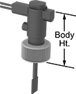
Insertion-Mount Flow Switches
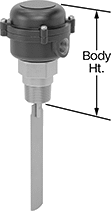 | 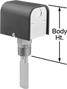 |
Threaded Connection with NEMA 4X Rating | Threaded Connection |
Avoid complicated inline installation—these flow switches insert into a tee or pipe outlet, so you don’t need to disassemble your pipeline. They have a paddle that’s pushed as your liquid moves through to determine flow. When the paddle reaches a set position determined by the set point, it activates or deactivates equipment. They are single pole, double throw (SPDT) and can either turn one device from off to on (normally open) or on to off (normally closed). They should be mounted vertically into a large-diameter horizontal pipeline, so liquid pushes the paddle.
These flow switches are calibrated with water. You can use them with other liquids, but they may not measure accurately if the liquid’s viscosity differs from water.
Choose a fitting material that is compatible with the liquid you're running through your line.
316 Stainless Steel Body and Brass Body—Switches with a brass or 316 stainless steel body have multiple paddles you can choose between to get you closest to your set point. For a higher set point, loosen the locking washers to remove the largest paddles. You can also trim the paddles to fine-tune your set point. The more you trim, the higher the set point.
316 Stainless Steel Fitting and Brass Fitting—Brass and 316 stainless steel fittings resist impact better than Noryl fittings.
NEMA 4X Enclosure Rating—NEMA 4X rated switches protect against dust, weather, and washdowns.
For Pipe Size | Flow Set Point Range, gpm | Max. Flow Rate, gpm | Paddle Material | Max. Pressure @ Temp. | Temp. Range, ° F | Max. Switching Current @ Voltage | Body Ht. | Enclosure Rating | Certification | Each | |||||||||||||||||||||||||||||||||||||||||||||||||||||||||||||||||||||||||||||||||||||||||
|---|---|---|---|---|---|---|---|---|---|---|---|---|---|---|---|---|---|---|---|---|---|---|---|---|---|---|---|---|---|---|---|---|---|---|---|---|---|---|---|---|---|---|---|---|---|---|---|---|---|---|---|---|---|---|---|---|---|---|---|---|---|---|---|---|---|---|---|---|---|---|---|---|---|---|---|---|---|---|---|---|---|---|---|---|---|---|---|---|---|---|---|---|---|---|---|---|---|---|---|
Brass Body with 1 NPT Male Threaded Brass Fittings | |||||||||||||||||||||||||||||||||||||||||||||||||||||||||||||||||||||||||||||||||||||||||||||||||||
Set-Point-Adjustment Removable Layered Paddles, Set-Point-Adjustment Trimmable Paddles | |||||||||||||||||||||||||||||||||||||||||||||||||||||||||||||||||||||||||||||||||||||||||||||||||||
| 1 2 4 6 | 4.9 to 17.6 13.7 to 56.4 35.3 to 118 60.3 to 245 | 27, 105, 397, 900 | 304 Stainless Steel | 160 psi @ 70° F | 33 to 225 | 3.7 amp @ 240V AC 7.4 amp @ 120V AC | 5" | NEMA 4X | C-UL Listed UL Recognized Component | 4971K5 | 0000000 | ||||||||||||||||||||||||||||||||||||||||||||||||||||||||||||||||||||||||||||||||||||||||
| 1 2 4 6 | 6 to 10.2 18.8 to 32.8 39.7 to 73.5 79.2 to 166 | 27, 105, 397, 900 | 304 Stainless Steel | 160 psi @ 70° F | 33 to 300 | 3.7 amp @ 240V AC 7.4 amp @ 120V AC | 5" | — | C-UL Listed UL Listed | 4971K3 | 000000 | ||||||||||||||||||||||||||||||||||||||||||||||||||||||||||||||||||||||||||||||||||||||||
316 Stainless Steel Body with 1 NPT Male Threaded 316 Stainless Steel Fittings | |||||||||||||||||||||||||||||||||||||||||||||||||||||||||||||||||||||||||||||||||||||||||||||||||||
Set-Point-Adjustment Removable Layered Paddles, Set-Point-Adjustment Trimmable Paddles | |||||||||||||||||||||||||||||||||||||||||||||||||||||||||||||||||||||||||||||||||||||||||||||||||||
| 1 2 4 6 | 6 to 10.2 18.8 to 32.8 39.7 to 73.5 79.2 to 166 | 27, 105, 397, 900 | 304 Stainless Steel | 160 psi @ 70° F | 33 to 300 | 3.7 amp @ 240V AC 7.4 amp @ 120V AC | 5" | — | C-UL Listed UL Listed | 4971K4 | 000000 | ||||||||||||||||||||||||||||||||||||||||||||||||||||||||||||||||||||||||||||||||||||||||
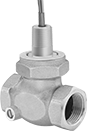
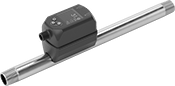
Flow Switches
Straight
 |
Conduit | |||||||||||||||||||||||||||||||||||||||||||||||||||||||||||||||||||||||||||||||||||||||||||||||||||
|---|---|---|---|---|---|---|---|---|---|---|---|---|---|---|---|---|---|---|---|---|---|---|---|---|---|---|---|---|---|---|---|---|---|---|---|---|---|---|---|---|---|---|---|---|---|---|---|---|---|---|---|---|---|---|---|---|---|---|---|---|---|---|---|---|---|---|---|---|---|---|---|---|---|---|---|---|---|---|---|---|---|---|---|---|---|---|---|---|---|---|---|---|---|---|---|---|---|---|---|
Pipe Connections | Flow Set Point, gpm | Max. Pressure @ Temp. | Temp. Range, ° F | Voltage, V AC | Max. Switching Current @ Voltage | Trade Size | Thread Type | Gender | End-to-End Lg. | Each | |||||||||||||||||||||||||||||||||||||||||||||||||||||||||||||||||||||||||||||||||||||||||
Bronze Body | |||||||||||||||||||||||||||||||||||||||||||||||||||||||||||||||||||||||||||||||||||||||||||||||||||
| 1 NPT Female | 1 to 6 | 400 psi @ 70° F | -20 to 200 | 120/240 | 200 mA @ 240V AC 400 mA @ 120V AC | 1/2 | NPT | Male | 3 1/4" | 4980K22 | 0000000 | ||||||||||||||||||||||||||||||||||||||||||||||||||||||||||||||||||||||||||||||||||||||||
| 1 NPT Female | 2 to 8 | 400 psi @ 70° F | -20 to 200 | 120/240 | 200 mA @ 240V AC 400 mA @ 120V AC | 1/2 | NPT | Male | 3 1/4" | 4980K24 | 000000 | ||||||||||||||||||||||||||||||||||||||||||||||||||||||||||||||||||||||||||||||||||||||||
| 1 NPT Female | 5 to 15 | 400 psi @ 70° F | -20 to 200 | 120/240 | 200 mA @ 240V AC 400 mA @ 120V AC | 1/2 | NPT | Male | 3 1/4" | 4980K26 | 000000 | ||||||||||||||||||||||||||||||||||||||||||||||||||||||||||||||||||||||||||||||||||||||||
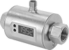
Electronic Insertion-Mount Flow Switches
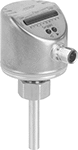 |
Instead of disassembling your system for inline installation, thread these flow switches onto a mounting adapter (sold separately) and insert them into a pipe tee or pipe outlet. They send digital signals to your programmable logic controller (PLC) to activate automated controls or alarms when they reach a set flow rate. To calculate the flow rate, they generate a small amount of heat, then measure the cooling effect your liquid or gas has on it. This makes them ideal in applications with fluctuating temperatures. Use the buttons on the display to adjust the set point and other settings. These switches are accurate in any mounting position.
IP65 rated switches protect against dust and washdowns. IP67 rated switches withstand temporary submersion.
Flow Set Point | 1 13/16" Probe Length | ||||||||||||||||||||||||||||||||||||||||||||||||||||||||||||||||||||||||||||||||||||||||||||||||||
|---|---|---|---|---|---|---|---|---|---|---|---|---|---|---|---|---|---|---|---|---|---|---|---|---|---|---|---|---|---|---|---|---|---|---|---|---|---|---|---|---|---|---|---|---|---|---|---|---|---|---|---|---|---|---|---|---|---|---|---|---|---|---|---|---|---|---|---|---|---|---|---|---|---|---|---|---|---|---|---|---|---|---|---|---|---|---|---|---|---|---|---|---|---|---|---|---|---|---|---|
For Pipe Size | For Liquids, gpm | For Gas, scfm | Max. Pressure @ Temp. | Temp. Range, ° F | Voltage, V DC | Max. Switching Current @ Voltage | Body Ht. | Enclosure Rating | Certification | Each | |||||||||||||||||||||||||||||||||||||||||||||||||||||||||||||||||||||||||||||||||||||||||
304 Stainless Steel Body with 316 Stainless Steel Fittings | |||||||||||||||||||||||||||||||||||||||||||||||||||||||||||||||||||||||||||||||||||||||||||||||||||
1 Digital NPN Signal Output | |||||||||||||||||||||||||||||||||||||||||||||||||||||||||||||||||||||||||||||||||||||||||||||||||||
| 1/4 1/2 3/4 1 | 0.02 to 1.5 0.05 to 4.9 0.13 to 12.7 0.23 to 23 | 0.14 to 2 0.54 to 8.05 1.21 to 18.11 2.15 to 32.21 | 4,300 psi @ 70° F | -10 to 175 | 36 | 250 mA @ 19V DC 250 mA @ 36V DC | 2 11/16" | IP65, IP67 | C-UL Listed UL Listed CE Marked | 4547N13 | 0000000 | ||||||||||||||||||||||||||||||||||||||||||||||||||||||||||||||||||||||||||||||||||||||||
1 Digital PNP Signal Output | |||||||||||||||||||||||||||||||||||||||||||||||||||||||||||||||||||||||||||||||||||||||||||||||||||
| 1/4 1/2 3/4 1 | 0.02 to 1.5 0.05 to 4.9 0.13 to 12.7 0.23 to 23 | 0.14 to 2 0.54 to 8.05 1.21 to 18.11 2.15 to 32.21 | 4,300 psi @ 70° F | -10 to 175 | 36 | 250 mA @ 36V DC 250 mA @ 18V DC | 2 11/16" | IP65, IP67 | C-UL Listed UL Listed CE Marked | 4547N11 | 000000 | ||||||||||||||||||||||||||||||||||||||||||||||||||||||||||||||||||||||||||||||||||||||||
2 Digital NPN Signal Output | |||||||||||||||||||||||||||||||||||||||||||||||||||||||||||||||||||||||||||||||||||||||||||||||||||
| 1/4 1/2 3/4 1 | 0.02 to 1.5 0.05 to 4.9 0.13 to 12.7 0.23 to 23 | 0.14 to 2 0.54 to 8.05 1.21 to 18.11 2.15 to 32.21 | 4,300 psi @ 70° F | -10 to 175 | 36 | 250 mA @ 19V DC 250 mA @ 36V DC | 2 11/16" | IP65, IP67 | C-UL Listed UL Listed CE Marked | 4547N14 | 000000 | ||||||||||||||||||||||||||||||||||||||||||||||||||||||||||||||||||||||||||||||||||||||||
2 Digital PNP Signal Output | |||||||||||||||||||||||||||||||||||||||||||||||||||||||||||||||||||||||||||||||||||||||||||||||||||
| 1/4 1/2 3/4 1 | 0.02 to 1.5 0.05 to 4.9 0.13 to 12.7 0.23 to 23 | 0.14 to 2 0.54 to 8.05 1.21 to 18.11 2.15 to 32.21 | 4,300 psi @ 70° F | -10 to 175 | 36 | 250 mA @ 36V DC 250 mA @ 18V DC | 2 11/16" | IP65, IP67 | C-UL Listed UL Listed CE Marked | 4547N12 | 000000 | ||||||||||||||||||||||||||||||||||||||||||||||||||||||||||||||||||||||||||||||||||||||||
Fixed-Set-Point Insertion-Mount Flow Switches
 |
Easy to install, these flow switches come already set to a specific set point and don’t require you to disassemble your pipeline. Instead of mounting them inline, insert them into an unthreaded PVC pipe tee or pipe outlet in large-diameter pipe. They have a paddle that’s pushed as your liquid moves through to determine flow. When the paddle reaches a set position determined by the set point, it activates or deactivates equipment. All are single pole, double throw (SPDT) and can either turn one device from off to on (normally open) or on to off (normally closed). IP rated, they seal out dust and can be lightly rinsed.
They should be mounted vertically into a horizontal pipeline, so liquid pushes the paddle. Secure them with PVC cement and primer (not included).
These flow switches are calibrated with water. You can use them with other liquids, but they may not measure accurately if the liquid’s viscosity differs from water.
Pipe Connections | For Pipe Size | Set Point, gpm | Max. Flow Rate, gpm | Max. Pressure @ Temp. | Temp. Range, ° F | Voltage | Max. Switching Current @ Voltage | Body Ht. | Enclosure Rating | Specs. Met | Each | ||||||||||||||||||||||||||||||||||||||||||||||||||||||||||||||||||||||||||||||||||||||||
|---|---|---|---|---|---|---|---|---|---|---|---|---|---|---|---|---|---|---|---|---|---|---|---|---|---|---|---|---|---|---|---|---|---|---|---|---|---|---|---|---|---|---|---|---|---|---|---|---|---|---|---|---|---|---|---|---|---|---|---|---|---|---|---|---|---|---|---|---|---|---|---|---|---|---|---|---|---|---|---|---|---|---|---|---|---|---|---|---|---|---|---|---|---|---|---|---|---|---|---|
Noryl Body with Socket-Connect PVC Fittings | |||||||||||||||||||||||||||||||||||||||||||||||||||||||||||||||||||||||||||||||||||||||||||||||||||
| 3/4 | 1 1 1/4 | 2.7, 6.8 | 31, 40 | 160 psi @ 70° F | -13 to 212 | 230V AC/48V DC | 1 amp @ 230V AC 1 amp @ 48V DC | 2 1/2" | IP65 | UL 508 | 2766K115 | 0000000 | |||||||||||||||||||||||||||||||||||||||||||||||||||||||||||||||||||||||||||||||||||||||
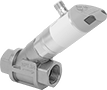
Electronic Flow Switches
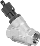 |
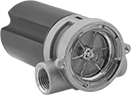
When these switches reach a set flow rate, they send digital signals to your programmable logic controller (PLC) to activate automated controls or alarms. Use the adjustment screw to select their set point. As flowing liquid pushes an internal piston, the switch reads the position of the piston to measure the flow. When the piston passes the set point, the switch actuates. They must be mounted horizontally to function correctly. IP rated, they withstand dust, washdowns, and temporary submersion.
These switches are calibrated with and measure water accurately. They can also be used with other liquids by applying your liquid’s specific-gravity conversion factor to calculate the new set point.
Pipe Connections | Flow Set Point, gpm | Max. Pressure @ Temp. | Temp. Range, ° F | Voltage, V DC | Max. Switching Current @ Voltage | End-to-End Lg. | Enclosure Rating | Certification | Each | ||||||||||||||||||||||||||||||||||||||||||||||||||||||||||||||||||||||||||||||||||||||||||
|---|---|---|---|---|---|---|---|---|---|---|---|---|---|---|---|---|---|---|---|---|---|---|---|---|---|---|---|---|---|---|---|---|---|---|---|---|---|---|---|---|---|---|---|---|---|---|---|---|---|---|---|---|---|---|---|---|---|---|---|---|---|---|---|---|---|---|---|---|---|---|---|---|---|---|---|---|---|---|---|---|---|---|---|---|---|---|---|---|---|---|---|---|---|---|---|---|---|---|---|
Aluminum/Brass/Plastic Body with Threaded Nickel-Plated Brass Fittings | |||||||||||||||||||||||||||||||||||||||||||||||||||||||||||||||||||||||||||||||||||||||||||||||||||
1 PNP Signal Output | |||||||||||||||||||||||||||||||||||||||||||||||||||||||||||||||||||||||||||||||||||||||||||||||||||
| 1 NPT Female | 1.32 to 26.4 | 360 psi @ 70° F | 32 to 185 | 30 | 100 mA @ 30V DC | 3 5/8" | IP65, IP67 | C-UL Listed UL Listed CE Marked | 4546N12 | 0000000 | |||||||||||||||||||||||||||||||||||||||||||||||||||||||||||||||||||||||||||||||||||||||||
Flow Switches with Sight
 |
Flow Set Point, gpm | Max. Pressure @ Temp. | Temp. Range, ° F | Max. Switching Current @ Voltage | Mounting Position | End-to-End Lg. | Certification | Each | ||||||||||||||||||||||||||||||||||||||||||||||||||||||||||||||||||||||||||||||||||||||||||||
|---|---|---|---|---|---|---|---|---|---|---|---|---|---|---|---|---|---|---|---|---|---|---|---|---|---|---|---|---|---|---|---|---|---|---|---|---|---|---|---|---|---|---|---|---|---|---|---|---|---|---|---|---|---|---|---|---|---|---|---|---|---|---|---|---|---|---|---|---|---|---|---|---|---|---|---|---|---|---|---|---|---|---|---|---|---|---|---|---|---|---|---|---|---|---|---|---|---|---|---|
Brass Body with Brass Fittings | |||||||||||||||||||||||||||||||||||||||||||||||||||||||||||||||||||||||||||||||||||||||||||||||||||
1 NPT Female | |||||||||||||||||||||||||||||||||||||||||||||||||||||||||||||||||||||||||||||||||||||||||||||||||||
| 8 to 60 | 200 psi @ 70° F | 33 to 212 | 95 mA @ 115V AC | Any Angle | 3 15/16" | CE Marked UL Recognized Component | 4138K16 | 0000000 | |||||||||||||||||||||||||||||||||||||||||||||||||||||||||||||||||||||||||||||||||||||||||||
316 Stainless Steel Body with 316 Stainless Steel Fittings | |||||||||||||||||||||||||||||||||||||||||||||||||||||||||||||||||||||||||||||||||||||||||||||||||||
1 NPT Female | |||||||||||||||||||||||||||||||||||||||||||||||||||||||||||||||||||||||||||||||||||||||||||||||||||
| 1.5 to 15 | 200 psi @ 70° F | 20 to 225 | 5 amp @ 120V AC 5 amp @ 240V AC | Horizontal | 5 1/4" | CE Marked VDE Certified | 4138K112 | 000000 | |||||||||||||||||||||||||||||||||||||||||||||||||||||||||||||||||||||||||||||||||||||||||||
| 3 to 30 | 200 psi @ 70° F | 20 to 225 | 5 amp @ 120V AC 5 amp @ 240V AC | Horizontal | 5 1/4" | CE Marked VDE Certified | 4138K113 | 000000 | |||||||||||||||||||||||||||||||||||||||||||||||||||||||||||||||||||||||||||||||||||||||||||
| 8 to 60 | 200 psi @ 70° F | 33 to 212 | 95 mA @ 115V AC | Any Angle | 3 15/16" | CE Marked UL Recognized Component | 4138K21 | 000000 | |||||||||||||||||||||||||||||||||||||||||||||||||||||||||||||||||||||||||||||||||||||||||||
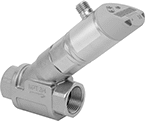
Variable-Pressure Flow Switches
 |
Accurate even in applications where pressure fluctuates regularly, these flow switches split flow into two paths and measure their difference in pressure drop to calculate the flow rate of liquid. They activate or deactivate equipment when the flow rate reaches your set point. Tighten or loosen the adjustment screw to choose your set point anywhere within the range. They measure accurately no matter their mounting position. All are single pole, double throw (SPDT) and can either turn one device from off to on (normally open) or on to off (normally closed). Rated NEMA 4X and IP66, they seal out dust and protect against washdowns and corrosion.
These switches are calibrated with water. They can also be used with other liquids but may not measure accurately if their viscosity is significantly different.
Flow Set Point, gpm | Max. Pressure @ Temp. | Temp. Range, ° F | Voltage | Max. Switching Current @ Voltage | Conduit Trade Size | End-to-End Lg. | Each | ||||||||||||||||||||||||||||||||||||||||||||||||||||||||||||||||||||||||||||||||||||||||||||
|---|---|---|---|---|---|---|---|---|---|---|---|---|---|---|---|---|---|---|---|---|---|---|---|---|---|---|---|---|---|---|---|---|---|---|---|---|---|---|---|---|---|---|---|---|---|---|---|---|---|---|---|---|---|---|---|---|---|---|---|---|---|---|---|---|---|---|---|---|---|---|---|---|---|---|---|---|---|---|---|---|---|---|---|---|---|---|---|---|---|---|---|---|---|---|---|---|---|---|---|
Bronze Body | |||||||||||||||||||||||||||||||||||||||||||||||||||||||||||||||||||||||||||||||||||||||||||||||||||
1 NPT Female | |||||||||||||||||||||||||||||||||||||||||||||||||||||||||||||||||||||||||||||||||||||||||||||||||||
| 2 to 15 | 400 psi @ 70° F | -30 to 212 | 120V AC/175V DC | 180 mA @ 120V AC 250 mA @ 175V DC | 1/2 | 3 1/16" | 2913T241 | 0000000 | |||||||||||||||||||||||||||||||||||||||||||||||||||||||||||||||||||||||||||||||||||||||||||
| 3 to 20 | 400 psi @ 70° F | -30 to 212 | 120V AC/175V DC | 180 mA @ 120V AC 250 mA @ 175V DC | 1/2 | 3 1/16" | 2913T242 | 000000 | |||||||||||||||||||||||||||||||||||||||||||||||||||||||||||||||||||||||||||||||||||||||||||
| 4 to 30 | 400 psi @ 70° F | -30 to 212 | 120V AC/175V DC | 180 mA @ 120V AC 250 mA @ 175V DC | 1/2 | 3 1/16" | 2913T243 | 000000 | |||||||||||||||||||||||||||||||||||||||||||||||||||||||||||||||||||||||||||||||||||||||||||
| 5 to 40 | 400 psi @ 70° F | -30 to 212 | 120V AC/175V DC | 180 mA @ 120V AC 250 mA @ 175V DC | 1/2 | 3 1/16" | 2913T244 | 000000 | |||||||||||||||||||||||||||||||||||||||||||||||||||||||||||||||||||||||||||||||||||||||||||
Fixed-Set-Point Hazardous-Location Flow Switches
 |
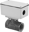
Safe to use where flammable gases and combustible dust may be present, these switches activate or deactivate when your flow reaches a factory-set level. All are UL listed for hazardous environments. Because their set point is fixed, they’re ready to go, making them easy to install. They actuate when your flowing liquid or gas pushes their paddle into a set position. These switches are single pole, double throw (SPDT) and can turn one device from off to on (normally open) or from on to off (normally closed). They must be mounted horizontally to function accurately.
These switches are calibrated with water and air. They can also be used with other liquids and gases but may not measure accurately if their viscosity is significantly different.
Set Point | Conduit | ||||||||||||||||||||||||||||||||||||||||||||||||||||||||||||||||||||||||||||||||||||||||||||||||||
|---|---|---|---|---|---|---|---|---|---|---|---|---|---|---|---|---|---|---|---|---|---|---|---|---|---|---|---|---|---|---|---|---|---|---|---|---|---|---|---|---|---|---|---|---|---|---|---|---|---|---|---|---|---|---|---|---|---|---|---|---|---|---|---|---|---|---|---|---|---|---|---|---|---|---|---|---|---|---|---|---|---|---|---|---|---|---|---|---|---|---|---|---|---|---|---|---|---|---|---|
Pipe Connections | For Liquids, gpm | For Gas, scfm | Max. Pressure @ Temp. | Temp. Range, ° F | Voltage, V AC | Max. Switching Current @ Voltage | Trade Size | Thread Type | Gender | End-to-End Lg. | Enclosure Rating | Certification | Each | ||||||||||||||||||||||||||||||||||||||||||||||||||||||||||||||||||||||||||||||||||||||
304 Stainless Steel Body with Threaded 304 Stainless Steel Fittings | |||||||||||||||||||||||||||||||||||||||||||||||||||||||||||||||||||||||||||||||||||||||||||||||||||
| 1 NPT Female | 3 | 14 | 2,000 psi @ 70° F | -4 to 220 | 120/240 | 5 amp @ 120V AC | 3/4 | NPT | Male | 3" | NEMA 4 | UL Listed CE Marked | 47565K63 | 0000000 | |||||||||||||||||||||||||||||||||||||||||||||||||||||||||||||||||||||||||||||||||||||
Brass Body with Threaded Brass Fittings | |||||||||||||||||||||||||||||||||||||||||||||||||||||||||||||||||||||||||||||||||||||||||||||||||||
| 1 NPT Female | 3 | 14 | 250 psi @ 70° F | -4 to 220 | 120/240 | 5 amp @ 120V AC | 3/4 | NPT | Male | 2 1/2" | NEMA 4 | UL Listed CE Marked | 47565K33 | 000000 | |||||||||||||||||||||||||||||||||||||||||||||||||||||||||||||||||||||||||||||||||||||
Flow Transmitters with Sight
 |
Flow Measurement Type | Pipe Connections | Flow Range, gpm | End-to-End Lg. | Accuracy | Max. Pressure @ Temp. | Temp. Range, ° F | Seal Material | Input Voltage Range, V DC | Mounting Position | Field Recalibratable | Pulse Freq., Hz | Each | |||||||||||||||||||||||||||||||||||||||||||||||||||||||||||||||||||||||||||||||||||||||
|---|---|---|---|---|---|---|---|---|---|---|---|---|---|---|---|---|---|---|---|---|---|---|---|---|---|---|---|---|---|---|---|---|---|---|---|---|---|---|---|---|---|---|---|---|---|---|---|---|---|---|---|---|---|---|---|---|---|---|---|---|---|---|---|---|---|---|---|---|---|---|---|---|---|---|---|---|---|---|---|---|---|---|---|---|---|---|---|---|---|---|---|---|---|---|---|---|---|---|---|
One 4-20 mA Analog Transmitter Output—Wire Lead Connection | |||||||||||||||||||||||||||||||||||||||||||||||||||||||||||||||||||||||||||||||||||||||||||||||||||
316 Stainless Steel Body with 316 Stainless Steel Fitting | |||||||||||||||||||||||||||||||||||||||||||||||||||||||||||||||||||||||||||||||||||||||||||||||||||
| Turbine | 1 NPT Female | 1.5 to 15 | 5 1/4" | ±2% | 200 psi @ 70° F | 20 to 212 | Buna-N | 12 to 24 | Any Angle | No | — | 9687K211 | 000000000 | ||||||||||||||||||||||||||||||||||||||||||||||||||||||||||||||||||||||||||||||||||||||
| Turbine | 1 NPT Female | 5 to 50 | 5 1/4" | ±2% | 200 psi @ 70° F | 20 to 212 | Buna-N | 12 to 24 | Any Angle | No | — | 9687K212 | 00000000 | ||||||||||||||||||||||||||||||||||||||||||||||||||||||||||||||||||||||||||||||||||||||
One 0-5V DC Analog Transmitter Output—Wire Lead Connection | |||||||||||||||||||||||||||||||||||||||||||||||||||||||||||||||||||||||||||||||||||||||||||||||||||
316 Stainless Steel Body with 316 Stainless Steel Fitting | |||||||||||||||||||||||||||||||||||||||||||||||||||||||||||||||||||||||||||||||||||||||||||||||||||
| Turbine | 1 NPT Female | 1.5 to 15 | 5 1/4" | ±2% | 200 psi @ 70° F | 20 to 212 | Buna-N | 12 to 24 | Any Angle | No | — | 9687K181 | 00000000 | ||||||||||||||||||||||||||||||||||||||||||||||||||||||||||||||||||||||||||||||||||||||
| Turbine | 1 NPT Female | 5 to 50 | 5 1/4" | ±2% | 200 psi @ 70° F | 20 to 212 | Buna-N | 12 to 24 | Any Angle | No | — | 9687K182 | 00000000 | ||||||||||||||||||||||||||||||||||||||||||||||||||||||||||||||||||||||||||||||||||||||
One Digital Pulse Output—Wire Lead Connection | |||||||||||||||||||||||||||||||||||||||||||||||||||||||||||||||||||||||||||||||||||||||||||||||||||
Brass Body with Brass Fitting | |||||||||||||||||||||||||||||||||||||||||||||||||||||||||||||||||||||||||||||||||||||||||||||||||||
| Turbine | 1 NPT Female | 8 to 60 | 3 15/16" | ±15% | 200 psi @ 70° F | 33 to 212 | Fluoroelastomer | 4.5 to 24 | Any Angle | No | 15 to 225 | 9687K24 | 000000 | ||||||||||||||||||||||||||||||||||||||||||||||||||||||||||||||||||||||||||||||||||||||
316 Stainless Steel Body with 316 Stainless Steel Fitting | |||||||||||||||||||||||||||||||||||||||||||||||||||||||||||||||||||||||||||||||||||||||||||||||||||
| Turbine | 1 NPT Female | 8 to 60 | 3 15/16" | ±15% | 200 psi @ 70° F | 33 to 212 | Fluoroelastomer | 4.5 to 24 | Any Angle | No | 15 to 225 | 9687K34 | 000000 | ||||||||||||||||||||||||||||||||||||||||||||||||||||||||||||||||||||||||||||||||||||||
High-Pressure Flow Switches for Oil
 |
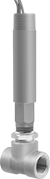
Measure the flow rate of oil at pressures up to 3,600 psi to activate or deactivate equipment. Designed to compensate for viscosity and density changes, these switches have an adjustment screw to select your specific flow rate within the set point range. As flowing liquid pushes an internal piston, the switch reads the position of the piston to measure the flow. When the piston passes the set point, the switch actuates. These switches are single pole, double throw (SPDT) and can turn one device from off to on (normally open) or from on to off (normally closed). Their IP65 rating protects them from dust and low-pressure washdowns, such as from a garden hose. All are accurate in any mounting position.
These switches are calibrated with and measure oil accurately. They can also be used with other liquids by applying your liquid’s specific-gravity conversion factor to calculate the new set point.
Pipe Connections | Flow Set Point, gpm | Approx. Difference Between Set Point and Reset Point | Max. Pressure @ Temp. | Max. Temp., ° F | Max. Switching Current @ Voltage | Port-to-Port Lg. | Enclosure Rating | Each | |||||||||||||||||||||||||||||||||||||||||||||||||||||||||||||||||||||||||||||||||||||||||||
|---|---|---|---|---|---|---|---|---|---|---|---|---|---|---|---|---|---|---|---|---|---|---|---|---|---|---|---|---|---|---|---|---|---|---|---|---|---|---|---|---|---|---|---|---|---|---|---|---|---|---|---|---|---|---|---|---|---|---|---|---|---|---|---|---|---|---|---|---|---|---|---|---|---|---|---|---|---|---|---|---|---|---|---|---|---|---|---|---|---|---|---|---|---|---|---|---|---|---|---|
SPDT | |||||||||||||||||||||||||||||||||||||||||||||||||||||||||||||||||||||||||||||||||||||||||||||||||||
Brass Body with Brass Fittings | |||||||||||||||||||||||||||||||||||||||||||||||||||||||||||||||||||||||||||||||||||||||||||||||||||
| 1 NPT Female | 2 to 20 | Adjustable | 3,600 psi @ 70° F | 212 | 1 amp @ 100V AC 0.42 amp @ 240V AC 1 amp @ 60V DC 0.26 amp @ 230V DC | 7 5/16" | IP65 | 4562N18 | 0000000 | ||||||||||||||||||||||||||||||||||||||||||||||||||||||||||||||||||||||||||||||||||||||||||
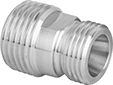
Build-Your-Own Flanged Pipe Flow Transmitters
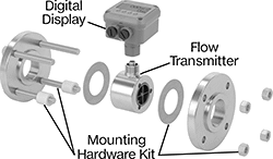 |
Components Sold Separately (Pipe Flanges Not Included) |
Flow Transmitters
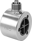 |
Flange | |||||||||||||||||||||||||||||||||||||||||||||||||||||||||||||||||||||||||||||||||||||||||||||||||||
|---|---|---|---|---|---|---|---|---|---|---|---|---|---|---|---|---|---|---|---|---|---|---|---|---|---|---|---|---|---|---|---|---|---|---|---|---|---|---|---|---|---|---|---|---|---|---|---|---|---|---|---|---|---|---|---|---|---|---|---|---|---|---|---|---|---|---|---|---|---|---|---|---|---|---|---|---|---|---|---|---|---|---|---|---|---|---|---|---|---|---|---|---|---|---|---|---|---|---|---|
Flow Measurement Type | Pipe Size | Flow Range, gpm | Bore Size | OD | Type | For Flange ANSI Class | End-to-End Lg. | Accuracy | Max. Pressure @ Temp. | Temp. Range, ° F | Mounting Position | Field Recalibratable | Pulse Frequency per Volume, pulse per gal. | Each | |||||||||||||||||||||||||||||||||||||||||||||||||||||||||||||||||||||||||||||||||||||
One Digital Pulse Output—2-Pin BNC Connection Plug | |||||||||||||||||||||||||||||||||||||||||||||||||||||||||||||||||||||||||||||||||||||||||||||||||||
316/316L Stainless Steel Body with 316/316L Stainless Steel Fitting | |||||||||||||||||||||||||||||||||||||||||||||||||||||||||||||||||||||||||||||||||||||||||||||||||||
| Turbine | 1 | 3 to 30 | 7/8" | 2" | Round | 150 | 4" | ±1.0% | 285 psi @ 70° F | -150 to 350 | Any Angle | No | 3,100 | 4408N11 | 0000000 | ||||||||||||||||||||||||||||||||||||||||||||||||||||||||||||||||||||||||||||||||||||
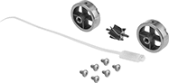 |
For Pipe Size | For Bore Size | For Flange ANSI Class | Includes | Each | ||
|---|---|---|---|---|---|---|
| 1 | 7/8" | 150 | 6 Screws, 2 Rotor Supports, One Rotor Assembly, One K-Factor Tag | 4408N19 | 0000000 |
Mounting Hardware Kits
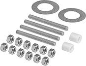 |
For Pipe Size | For Flange ANSI Class | Includes | Each | |||
|---|---|---|---|---|---|---|
| 1 | 150 | 4 Studs, 12 Nuts, 2 Gaskets, 2 Centering Rings | 4408N15 | 0000000 | ||
Flow, Pressure, and Temperature Transmitters for Gases
 |
Flow Measurement Type | Pipe Connections | Flow Range, scfm | End-to-End Lg. | Accuracy | Max. Pressure @ Temp. | Temp. Range, ° F | Seal Material | Input Voltage Range, V DC | Mounting Position | Field Recalibratable | Enclosure Rating | Each | |||||||||||||||||||||||||||||||||||||||||||||||||||||||||||||||||||||||||||||||||||||||
|---|---|---|---|---|---|---|---|---|---|---|---|---|---|---|---|---|---|---|---|---|---|---|---|---|---|---|---|---|---|---|---|---|---|---|---|---|---|---|---|---|---|---|---|---|---|---|---|---|---|---|---|---|---|---|---|---|---|---|---|---|---|---|---|---|---|---|---|---|---|---|---|---|---|---|---|---|---|---|---|---|---|---|---|---|---|---|---|---|---|---|---|---|---|---|---|---|---|---|---|
One Digital Switch/Pulse Output and One 4-20 mA Analog Transmitter/Digital Switch/Pulse Output—4-Pole M12 Connection Plug | |||||||||||||||||||||||||||||||||||||||||||||||||||||||||||||||||||||||||||||||||||||||||||||||||||
304 Stainless Steel Body with 304 Stainless Steel Fitting | |||||||||||||||||||||||||||||||||||||||||||||||||||||||||||||||||||||||||||||||||||||||||||||||||||
| Thermal | 1 NPT Male | 0.4 to 132 | 18 3/4" | ±6% | 230 psi @ 70° F | 14 to 140 | Fluoroelastomer | 18 to 30 | Any Angle | No | IP65, IP67 | 4384N12 | 000000000 | ||||||||||||||||||||||||||||||||||||||||||||||||||||||||||||||||||||||||||||||||||||||
Flow and Temperature Transmitters
 |
Variable Area Flow Measurement |
Flow Measurement Type | Pipe Connections | Flow Range, gph | End-to-End Lg. | Accuracy | Max. Pressure @ Temp. | Temp. Range, ° F | Seal Material | Input Voltage Range, V DC | Mounting Position | Field Recalibratable | Enclosure Rating | Each | |||||||||||||||||||||||||||||||||||||||||||||||||||||||||||||||||||||||||||||||||||||||
|---|---|---|---|---|---|---|---|---|---|---|---|---|---|---|---|---|---|---|---|---|---|---|---|---|---|---|---|---|---|---|---|---|---|---|---|---|---|---|---|---|---|---|---|---|---|---|---|---|---|---|---|---|---|---|---|---|---|---|---|---|---|---|---|---|---|---|---|---|---|---|---|---|---|---|---|---|---|---|---|---|---|---|---|---|---|---|---|---|---|---|---|---|---|---|---|---|---|---|---|
One Digital Switch/Pulse Output and One 4-20 mA Analog Transmitter/Digital Switch Output—4-Pole M12 Connection Plug | |||||||||||||||||||||||||||||||||||||||||||||||||||||||||||||||||||||||||||||||||||||||||||||||||||
316 Stainless Steel Body with 316 Stainless Steel Fitting | |||||||||||||||||||||||||||||||||||||||||||||||||||||||||||||||||||||||||||||||||||||||||||||||||||
| Variable Area | 1 NPT Female | 30 to 1,620 | 5 3/4" | ±5% | 362 psi @ 70° F | 14 to 212 | Fluoroelastomer | 18 to 30 | Any Angle | Yes | IP65, IP67 | 4401N14 | 0000000 | ||||||||||||||||||||||||||||||||||||||||||||||||||||||||||||||||||||||||||||||||||||||
Flow Transmitters
 |
Variable Area Flow Measurement |
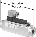
Send flow rate measurements to monitor and control equipment. Also known as transducers, these transmitters convert flow rate measurements to an electrical signal that can be interpreted by receiving devices, such as remote displays and programmable logic controllers (PLCs). As flow increases, the output signal increases. For your receiving device to interpret the signal, you will need to calibrate it for the measurement range and output signal of the transmitter. They only give accurate readings within the rated measurement range. Mount them directly inline with your system. They measure flow correctly no matter their mounting orientation.
These transmitters are calibrated with water. You can use them with other liquids, but they may not measure accurately if the liquid’s viscosity differs from water.
Variable Area Flow Measurement—Variable-area transmitters determine flow rate by tracking where the liquid pushes an internal piston.
Flow Measurement Type | Pipe Connections | Flow Range, gpm | End-to-End Lg. | Accuracy | Max. Pressure @ Temp. | Temp. Range, ° F | Seal Material | Input Voltage Range, V DC | Mounting Position | Field Recalibratable | Enclosure Rating | Each | |||||||||||||||||||||||||||||||||||||||||||||||||||||||||||||||||||||||||||||||||||||||
|---|---|---|---|---|---|---|---|---|---|---|---|---|---|---|---|---|---|---|---|---|---|---|---|---|---|---|---|---|---|---|---|---|---|---|---|---|---|---|---|---|---|---|---|---|---|---|---|---|---|---|---|---|---|---|---|---|---|---|---|---|---|---|---|---|---|---|---|---|---|---|---|---|---|---|---|---|---|---|---|---|---|---|---|---|---|---|---|---|---|---|---|---|---|---|---|---|---|---|---|
One 4-20 mA Analog Transmitter Output—4-Pole M12 Connection Plug | |||||||||||||||||||||||||||||||||||||||||||||||||||||||||||||||||||||||||||||||||||||||||||||||||||
316L Stainless Steel/Aluminum/Brass/Plastic Body with 316 Stainless Steel/Brass Fitting | |||||||||||||||||||||||||||||||||||||||||||||||||||||||||||||||||||||||||||||||||||||||||||||||||||
| Variable Area | 1 NPT Female | 0.5 to 27 | 3 5/8" | ±5% | 362 psi @ 212° F | 14 to 212 | Fluoroelastomer | 18 to 32 | Any Angle | No | IP65, IP67 | 4386N104 | 0000000 | ||||||||||||||||||||||||||||||||||||||||||||||||||||||||||||||||||||||||||||||||||||||
High-Accuracy Flow and Temperature Transmitters
 |
Flow Range | |||||||||||||||||||||||||||||||||||||||||||||||||||||||||||||||||||||||||||||||||||||||||||||||||||
|---|---|---|---|---|---|---|---|---|---|---|---|---|---|---|---|---|---|---|---|---|---|---|---|---|---|---|---|---|---|---|---|---|---|---|---|---|---|---|---|---|---|---|---|---|---|---|---|---|---|---|---|---|---|---|---|---|---|---|---|---|---|---|---|---|---|---|---|---|---|---|---|---|---|---|---|---|---|---|---|---|---|---|---|---|---|---|---|---|---|---|---|---|---|---|---|---|---|---|---|
Flow Measurement Type | Pipe Connections | Gallons per Minute, gpm | Liters per Minute, L/min | End-to-End Lg. | Accuracy | Max. Pressure @ Temp. | Temp. Range, ° F | Input Voltage Range, V DC | Mounting Position | Field Recalibratable | Enclosure Rating | Each | |||||||||||||||||||||||||||||||||||||||||||||||||||||||||||||||||||||||||||||||||||||||
Two 4-20 mA Analog Transmitter Outputs—4-Pole M12 Connection Plugs | |||||||||||||||||||||||||||||||||||||||||||||||||||||||||||||||||||||||||||||||||||||||||||||||||||
316 Stainless Steel/Plastic/Polybutylene Body with 316 Stainless Steel Fitting | |||||||||||||||||||||||||||||||||||||||||||||||||||||||||||||||||||||||||||||||||||||||||||||||||||
| Magnetic Induction | 1 NPT Female | 0.1 to 26.4 | 0.2 to 100 | 2 1/8" | ±2% | 225 psi @ 70° F | 0 to 175 | 20 to 30 | Any Angle | No | IP67 | 4397N103 | 0000000 | ||||||||||||||||||||||||||||||||||||||||||||||||||||||||||||||||||||||||||||||||||||||
