


Filter by
Body Material
For Use With
Wetted Parts Material
Switch Designation
Calibrated With
Gender
Fitting Material
Mounting Position
Maximum Pressure @ Temperature
Fitting Connection
Shape
Connects To
Maximum Switching Current @ Voltage
Thread Type
Flow Measurement Type
Certification
REACH
Mounting Location
Export Control Classification Number (ECCN)
DFARS Specialty Metals
RoHS
Fixed-Set-Point Flow Switches
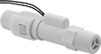 |
Style B |
Since they come factory set to a specific set point, these switches are easier to install than adjustable flow switches. As flowing liquid pushes an internal piston, the switch reads the position of the piston to measure the flow. When the piston passes the set point, the switch actuates. They’re accurate in any mounting position.
These switches are calibrated with and measure water accurately. They can also be used with other liquids by applying your liquid’s specific-gravity conversion factor to calculate the new set point.
Choose a fitting material that is compatible with the liquid you intend to run through your line.
Straight
|
Style B |
Polypropylene Fitting—Polypropylene and PPS fittings work with a wide range of chemicals. However, they can crack from impact or when overtightened.
SPST—SPST (single pole, single throw) switches turn one device from off to on (normally open).
Style | Pipe Size | Thread Type | Gender | Set Point, gpm | Approx. Difference Between Set Point and Reset Point, gpm | Max. Pressure @ Temp. | Temp. Range, ° F | Max. Switching Current @ Voltage | End-to-End Lg. | Mounting Position | Each | ||||||||||||||||||||||||||||||||||||||||||||||||||||||||||||||||||||||||||||||||||||||||
|---|---|---|---|---|---|---|---|---|---|---|---|---|---|---|---|---|---|---|---|---|---|---|---|---|---|---|---|---|---|---|---|---|---|---|---|---|---|---|---|---|---|---|---|---|---|---|---|---|---|---|---|---|---|---|---|---|---|---|---|---|---|---|---|---|---|---|---|---|---|---|---|---|---|---|---|---|---|---|---|---|---|---|---|---|---|---|---|---|---|---|---|---|---|---|---|---|---|---|---|
Polypropylene Body with Polypropylene Fittings | |||||||||||||||||||||||||||||||||||||||||||||||||||||||||||||||||||||||||||||||||||||||||||||||||||
SPST | |||||||||||||||||||||||||||||||||||||||||||||||||||||||||||||||||||||||||||||||||||||||||||||||||||
| B | 3/8 | NPT | Male | 0.25 | 0.05 | 125 psi @ 70° F | 33 to 212 | 400 mA @ 30V AC 170 mA @ 120V AC 80 mA @ 240V AC 300 mA @ 30V DC 130 mA @ 120V DC 60 mA @ 240V DC | 4" | Any Angle | 00000000 | 000000 | |||||||||||||||||||||||||||||||||||||||||||||||||||||||||||||||||||||||||||||||||||||||
| B | 3/8 | NPT | Male | 0.5 | 0.1 | 125 psi @ 70° F | 33 to 212 | 400 mA @ 30V AC 170 mA @ 120V AC 80 mA @ 240V AC 300 mA @ 30V DC 130 mA @ 120V DC 60 mA @ 240V DC | 4" | Any Angle | 00000000 | 00000 | |||||||||||||||||||||||||||||||||||||||||||||||||||||||||||||||||||||||||||||||||||||||
| B | 3/8 | NPT | Male | 1 | 0.2 | 125 psi @ 70° F | 33 to 212 | 400 mA @ 30V AC 170 mA @ 120V AC 80 mA @ 240V AC 300 mA @ 30V DC 130 mA @ 120V DC 60 mA @ 240V DC | 4" | Any Angle | 00000000 | 00000 | |||||||||||||||||||||||||||||||||||||||||||||||||||||||||||||||||||||||||||||||||||||||
| B | 3/8 | NPT | Male | 1.5 | 0.3 | 125 psi @ 70° F | 33 to 212 | 400 mA @ 30V AC 170 mA @ 120V AC 80 mA @ 240V AC 300 mA @ 30V DC 130 mA @ 120V DC 60 mA @ 240V DC | 4" | Any Angle | 00000000 | 00000 | |||||||||||||||||||||||||||||||||||||||||||||||||||||||||||||||||||||||||||||||||||||||
| B | 3/8 | NPT | Male | 2 | 0.4 | 125 psi @ 70° F | 33 to 212 | 400 mA @ 30V AC 170 mA @ 120V AC 80 mA @ 240V AC 300 mA @ 30V DC 130 mA @ 120V DC 60 mA @ 240V DC | 4" | Any Angle | 00000000 | 00000 | |||||||||||||||||||||||||||||||||||||||||||||||||||||||||||||||||||||||||||||||||||||||
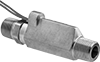
Fixed-Set-Point High-Pressure Flow Switches
Straight
 |
SPST—SPST (single pole, single throw) switches turn one device from off to on (normally open).
Pipe Connections | Set Point, gpm | Approx. Difference Between Set Point and Reset Point, gpm | Max. Pressure @ Temp. | Temp. Range, ° F | Max. Switching Current @ Voltage | End-to-End Lg. | Each | ||||||||||||||||||||||||||||||||||||||||||||||||||||||||||||||||||||||||||||||||||||||||||||
|---|---|---|---|---|---|---|---|---|---|---|---|---|---|---|---|---|---|---|---|---|---|---|---|---|---|---|---|---|---|---|---|---|---|---|---|---|---|---|---|---|---|---|---|---|---|---|---|---|---|---|---|---|---|---|---|---|---|---|---|---|---|---|---|---|---|---|---|---|---|---|---|---|---|---|---|---|---|---|---|---|---|---|---|---|---|---|---|---|---|---|---|---|---|---|---|---|---|---|---|
SPST | |||||||||||||||||||||||||||||||||||||||||||||||||||||||||||||||||||||||||||||||||||||||||||||||||||
Brass Body with Brass Fittings | |||||||||||||||||||||||||||||||||||||||||||||||||||||||||||||||||||||||||||||||||||||||||||||||||||
| 3/8 NPT Male | 0.25 | 0.05 | 1,500 psi @ 70° F | -20 to 275 | 0.4 amp @ 30V AC 0.17 amp @ 120V AC 0.08 amp @ 240V AC 0.3 amp @ 30V DC 0.13 amp @ 120V DC 0.06 amp @ 240V DC | 3 7/16" | 0000000 | 0000000 | |||||||||||||||||||||||||||||||||||||||||||||||||||||||||||||||||||||||||||||||||||||||||||
| 3/8 NPT Male | 0.5 | 0.1 | 1,500 psi @ 70° F | -20 to 275 | 0.4 amp @ 30V AC 0.17 amp @ 120V AC 0.08 amp @ 240V AC 0.3 amp @ 30V DC 0.13 amp @ 120V DC 0.06 amp @ 240V DC | 3 7/16" | 0000000 | 000000 | |||||||||||||||||||||||||||||||||||||||||||||||||||||||||||||||||||||||||||||||||||||||||||
| 3/8 NPT Male | 1 | 0.2 | 1,500 psi @ 70° F | -20 to 275 | 0.4 amp @ 30V AC 0.17 amp @ 120V AC 0.08 amp @ 240V AC 0.3 amp @ 30V DC 0.13 amp @ 120V DC 0.06 amp @ 240V DC | 3 7/16" | 0000000 | 000000 | |||||||||||||||||||||||||||||||||||||||||||||||||||||||||||||||||||||||||||||||||||||||||||
| 3/8 NPT Male | 1.5 | 0.3 | 1,500 psi @ 70° F | -20 to 275 | 0.4 amp @ 30V AC 0.17 amp @ 120V AC 0.08 amp @ 240V AC 0.3 amp @ 30V DC 0.13 amp @ 120V DC 0.06 amp @ 240V DC | 3 7/16" | 0000000 | 000000 | |||||||||||||||||||||||||||||||||||||||||||||||||||||||||||||||||||||||||||||||||||||||||||
| 3/8 NPT Male | 2 | 0.4 | 1,500 psi @ 70° F | -20 to 275 | 0.4 amp @ 30V AC 0.17 amp @ 120V AC 0.08 amp @ 240V AC 0.3 amp @ 30V DC 0.13 amp @ 120V DC 0.06 amp @ 240V DC | 3 7/16" | 0000000 | 000000 | |||||||||||||||||||||||||||||||||||||||||||||||||||||||||||||||||||||||||||||||||||||||||||
316 Stainless Steel Body with 316 Stainless Steel Fittings | |||||||||||||||||||||||||||||||||||||||||||||||||||||||||||||||||||||||||||||||||||||||||||||||||||
| 3/8 NPT Male | 0.25 | 0.05 | 1,500 psi @ 70° F | -20 to 275 | 0.4 amp @ 30V AC 0.17 amp @ 120V AC 0.08 amp @ 240V AC 0.3 amp @ 30V DC 0.13 amp @ 120V DC 0.06 amp @ 240V DC | 3 7/16" | 0000000 | 000000 | |||||||||||||||||||||||||||||||||||||||||||||||||||||||||||||||||||||||||||||||||||||||||||
| 3/8 NPT Male | 0.5 | 0.1 | 1,500 psi @ 70° F | -20 to 275 | 0.4 amp @ 30V AC 0.17 amp @ 120V AC 0.08 amp @ 240V AC 0.3 amp @ 30V DC 0.13 amp @ 120V DC 0.06 amp @ 240V DC | 3 7/16" | 0000000 | 000000 | |||||||||||||||||||||||||||||||||||||||||||||||||||||||||||||||||||||||||||||||||||||||||||
| 3/8 NPT Male | 2 | 0.4 | 1,500 psi @ 70° F | -20 to 275 | 0.4 amp @ 30V AC 0.17 amp @ 120V AC 0.08 amp @ 240V AC 0.3 amp @ 30V DC 0.13 amp @ 120V DC 0.06 amp @ 240V DC | 3 7/16" | 0000000 | 000000 | |||||||||||||||||||||||||||||||||||||||||||||||||||||||||||||||||||||||||||||||||||||||||||
Flow Transmitters
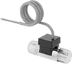 |
Turbine Flow Measurement |
Flow Measurement Type | Pipe Connections | Flow Range, gpm | End-to-End Lg. | Accuracy | Max. Pressure @ Temp. | Temp. Range, ° F | Input Voltage Range, V DC | Mounting Position | Field Recalibratable | Pulse Freq., Hz | Each | ||||||||||||||||||||||||||||||||||||||||||||||||||||||||||||||||||||||||||||||||||||||||
|---|---|---|---|---|---|---|---|---|---|---|---|---|---|---|---|---|---|---|---|---|---|---|---|---|---|---|---|---|---|---|---|---|---|---|---|---|---|---|---|---|---|---|---|---|---|---|---|---|---|---|---|---|---|---|---|---|---|---|---|---|---|---|---|---|---|---|---|---|---|---|---|---|---|---|---|---|---|---|---|---|---|---|---|---|---|---|---|---|---|---|---|---|---|---|---|---|---|---|---|
One Analog Transmitter/Digital Pulse Output—Wire Lead Connection | |||||||||||||||||||||||||||||||||||||||||||||||||||||||||||||||||||||||||||||||||||||||||||||||||||
Nylon Body with Nylon Fitting | |||||||||||||||||||||||||||||||||||||||||||||||||||||||||||||||||||||||||||||||||||||||||||||||||||
| Turbine | 3/8 NPT Male | 0.13 to 1.3 | 2 5/32" | ±3% | 362 psi @ 212° F | -4 to 212 | 5 to 24 | Any Angle | No | 56 to 565 | 00000000 | 0000000 | |||||||||||||||||||||||||||||||||||||||||||||||||||||||||||||||||||||||||||||||||||||||
| Turbine | 3/8 NPT Male | 0.26 to 4 | 2 5/32" | ±3% | 362 psi @ 212° F | -4 to 212 | 5 to 24 | Any Angle | No | 36 to 553 | 00000000 | 000000 | |||||||||||||||||||||||||||||||||||||||||||||||||||||||||||||||||||||||||||||||||||||||
| Turbine | 3/8 NPT Male | 0.53 to 9.2 | 2 5/32" | ±3% | 362 psi @ 212° F | -4 to 212 | 5 to 24 | Any Angle | No | 25 to 435 | 00000000 | 000000 | |||||||||||||||||||||||||||||||||||||||||||||||||||||||||||||||||||||||||||||||||||||||
Brass Body with Brass Fitting | |||||||||||||||||||||||||||||||||||||||||||||||||||||||||||||||||||||||||||||||||||||||||||||||||||
| Turbine | 3/8 NPT Male | 0.5 to 2.11 | 2 5/32" | ±3% | 362 psi @ 212° F | -4 to 212 | 5 to 24 | Any Angle | No | 132 to 559 | 00000000 | 000000 | |||||||||||||||||||||||||||||||||||||||||||||||||||||||||||||||||||||||||||||||||||||||
| Turbine | 3/8 NPT Male | 0.8 to 6.6 | 2 5/32" | ±3% | 362 psi @ 212° F | -4 to 212 | 5 to 24 | Any Angle | No | 46 to 383 | 00000000 | 000000 | |||||||||||||||||||||||||||||||||||||||||||||||||||||||||||||||||||||||||||||||||||||||
