


Filter by
Maximum Flow
Measures
Flow Measurement Unit
Body Material
Minimum Flow
Wetted Parts Material
Fitting Material
Maximum Pressure @ Temperature
Measurement Unit
Flow Measurement Type
Fitting Connection
Flow Set Point
Connects To
DFARS Specialty Metals
Export Control Classification Number (ECCN)
Input Voltage
Flow Transmitters
 |
Variable Area Flow Measurement |
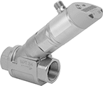
Send flow rate measurements to monitor and control equipment. Also known as transducers, these transmitters convert flow rate measurements to an electrical signal that can be interpreted by receiving devices, such as remote displays and programmable logic controllers (PLCs). As flow increases, the output signal increases. For your receiving device to interpret the signal, you will need to calibrate it for the measurement range and output signal of the transmitter. They only give accurate readings within the rated measurement range. Mount them directly inline with your system. They measure flow correctly no matter their mounting orientation.
These transmitters are calibrated with water. You can use them with other liquids, but they may not measure accurately if the liquid’s viscosity differs from water.
Variable Area Flow Measurement—Variable-area transmitters determine flow rate by tracking where the liquid pushes an internal piston.
Flow Measurement Type | Pipe Connections | Flow Range, gpm | End-to-End Lg. | Accuracy | Max. Pressure @ Temp. | Temp. Range, ° F | Seal Material | Input Voltage Range, V DC | Mounting Position | Field Recalibratable | Enclosure Rating | Each | |||||||||||||||||||||||||||||||||||||||||||||||||||||||||||||||||||||||||||||||||||||||
|---|---|---|---|---|---|---|---|---|---|---|---|---|---|---|---|---|---|---|---|---|---|---|---|---|---|---|---|---|---|---|---|---|---|---|---|---|---|---|---|---|---|---|---|---|---|---|---|---|---|---|---|---|---|---|---|---|---|---|---|---|---|---|---|---|---|---|---|---|---|---|---|---|---|---|---|---|---|---|---|---|---|---|---|---|---|---|---|---|---|---|---|---|---|---|---|---|---|---|---|
One 4-20 mA Analog Transmitter Output—4-Pole Micro M12 Connection Plug | |||||||||||||||||||||||||||||||||||||||||||||||||||||||||||||||||||||||||||||||||||||||||||||||||||
316L Stainless Steel/Aluminum/Brass/Plastic Body with 316 Stainless Steel/Brass Fitting | |||||||||||||||||||||||||||||||||||||||||||||||||||||||||||||||||||||||||||||||||||||||||||||||||||
| Variable Area | 3/4 NPT Female | 0.2 to 4 | 2 15/16" | -5% to 5% | 580 psi @ 212° F | 14 to 212 | Fluoroelastomer | 18 to 32 | Any Angle | No | IP65, IP67 | 00000000 | 0000000 | ||||||||||||||||||||||||||||||||||||||||||||||||||||||||||||||||||||||||||||||||||||||
| Variable Area | 3/4 NPT Female | 0.2 to 6 | 2 15/16" | -5% to 5% | 580 psi @ 212° F | 14 to 212 | Fluoroelastomer | 18 to 32 | Any Angle | No | IP65, IP67 | 00000000 | 000000 | ||||||||||||||||||||||||||||||||||||||||||||||||||||||||||||||||||||||||||||||||||||||
| Variable Area | 3/4 NPT Female | 0.2 to 10 | 2 15/16" | -5% to 5% | 580 psi @ 212° F | 14 to 212 | Fluoroelastomer | 18 to 32 | Any Angle | No | IP65, IP67 | 00000000 | 000000 | ||||||||||||||||||||||||||||||||||||||||||||||||||||||||||||||||||||||||||||||||||||||
| Variable Area | 1 NPT Female | 0.5 to 27 | 3 5/8" | -5% to 5% | 362 psi @ 212° F | 14 to 212 | Fluoroelastomer | 18 to 32 | Any Angle | No | IP65, IP67 | 00000000 | 000000 | ||||||||||||||||||||||||||||||||||||||||||||||||||||||||||||||||||||||||||||||||||||||
Flow and Temperature Transmitters
 |
Variable Area Flow Measurement |
 |
Vortex Flow Measurement |
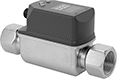
Send flow rate and temperature measurements simultaneously to a programmable logic controller (PLC), data logger, or other receiving device. Used to monitor status or control equipment, these transmitters, also known as transducers, convert measurements to an electrical signal that is interpreted by receiving devices. As flow or temperature increases, the output signal increases. For your receiving device to interpret the signal, you will need to calibrate it for the measurement range and output signal of the transmitter. They only give accurate readings within the rated measurement range. Mount them inline with your pipe system. They’ll measure flow correctly in any mounting orientation.
A digital display makes it easy to view readings and adjust settings at the source. To change settings and receive error messages remotely from your PLC or computer, program one of the outputs to use IO Link. You’ll need an IO Link controller (not included) to connect to your interface.
Variable Area Flow Measurement—Variable-area transmitters determine the flow rate by tracking where the liquid pushes the piston. They have two configurable outputs. One can be wired as an analog output or a digital switch. The other one can be wired as a digital switch, digital pulse output, or IO Link. Pulse outputs send flow data using spikes of voltage that match the input voltage of the transmitter. The higher the flow, the more pulses they send. These transmitters are calibrated with water, glycol solutions, and coolants but can be recalibrated in the field for other liquids.
Vortex Flow Measurement—Vortex transmitters determine the flow rate by measuring the size of the vortex created as liquid flows through them. They don’t have any moving parts that can break or get stuck. Use them only with liquids that are at least 95% water. They have one analog output for flow and another for temperature. The output for temperature can also be wired for IO Link.
Flow Measurement Type | Pipe Connections | Flow Range, gph | End-to-End Lg. | Accuracy | Max. Pressure @ Temp. | Temp. Range, ° F | Seal Material | Input Voltage Range, V DC | Mounting Position | Field Recalibratable | Enclosure Rating | Each | |||||||||||||||||||||||||||||||||||||||||||||||||||||||||||||||||||||||||||||||||||||||
|---|---|---|---|---|---|---|---|---|---|---|---|---|---|---|---|---|---|---|---|---|---|---|---|---|---|---|---|---|---|---|---|---|---|---|---|---|---|---|---|---|---|---|---|---|---|---|---|---|---|---|---|---|---|---|---|---|---|---|---|---|---|---|---|---|---|---|---|---|---|---|---|---|---|---|---|---|---|---|---|---|---|---|---|---|---|---|---|---|---|---|---|---|---|---|---|---|---|---|---|
One Digital Switch/Pulse Output and One 4-20 mA Analog Transmitter/Digital Switch Output—4-Pole Micro M12 Connection Plug | |||||||||||||||||||||||||||||||||||||||||||||||||||||||||||||||||||||||||||||||||||||||||||||||||||
316 Stainless Steel Body with 316 Stainless Steel Fitting | |||||||||||||||||||||||||||||||||||||||||||||||||||||||||||||||||||||||||||||||||||||||||||||||||||
| Variable Area | 3/4 NPT Female | 5 to 240 | 5 9/16" | -5% to 5% | 580 psi @ 70° F | 14 to 212 | Fluoroelastomer | 18 to 30 | Any Angle | Yes | IP65, IP67 | 0000000 | 0000000 | ||||||||||||||||||||||||||||||||||||||||||||||||||||||||||||||||||||||||||||||||||||||
| Variable Area | 3/4 NPT Female | 7 to 360 | 5 9/16" | -5% to 5% | 580 psi @ 70° F | 14 to 212 | Fluoroelastomer | 18 to 30 | Any Angle | Yes | IP65, IP67 | 0000000 | 000000 | ||||||||||||||||||||||||||||||||||||||||||||||||||||||||||||||||||||||||||||||||||||||
| Variable Area | 3/4 NPT Female | 10 to 600 | 5 9/16" | -5% to 5% | 580 psi @ 70° F | 14 to 212 | Fluoroelastomer | 18 to 30 | Any Angle | Yes | IP65, IP67 | 0000000 | 000000 | ||||||||||||||||||||||||||||||||||||||||||||||||||||||||||||||||||||||||||||||||||||||
| Variable Area | 1 NPT Female | 30 to 1,620 | 5 3/4" | -5% to 5% | 362 psi @ 70° F | 14 to 212 | Fluoroelastomer | 18 to 30 | Any Angle | Yes | IP65, IP67 | 0000000 | 000000 | ||||||||||||||||||||||||||||||||||||||||||||||||||||||||||||||||||||||||||||||||||||||
| Variable Area | 1 1/2 NPT Female | 60 to 3,000 | 6 3/16" | -5% to 5% | 362 psi @ 70° F | 14 to 212 | Fluoroelastomer | 18 to 30 | Any Angle | Yes | IP65, IP67 | 0000000 | 000000 | ||||||||||||||||||||||||||||||||||||||||||||||||||||||||||||||||||||||||||||||||||||||
Two 4-20 mA Analog Transmitter Outputs—4-Pole Micro M12 Connection Plugs | |||||||||||||||||||||||||||||||||||||||||||||||||||||||||||||||||||||||||||||||||||||||||||||||||||
316 Stainless Steel Body with 316 Stainless Steel Fitting | |||||||||||||||||||||||||||||||||||||||||||||||||||||||||||||||||||||||||||||||||||||||||||||||||||
| Vortex | 1/2 NPT Female | 16 to 317 | 4 11/16" | -2% to 2% | 172 psi @ 70° F | 14 to 190 | Fluoroelastomer | 18 to 30 | Any Angle | No | IP65, IP67 | 0000000 | 000000 | ||||||||||||||||||||||||||||||||||||||||||||||||||||||||||||||||||||||||||||||||||||||
| Vortex | 1/2 NPT Female | 32 to 634 | 4 11/16" | -2% to 2% | 172 psi @ 70° F | 14 to 190 | Fluoroelastomer | 18 to 30 | Any Angle | No | IP65, IP67 | 0000000 | 000000 | ||||||||||||||||||||||||||||||||||||||||||||||||||||||||||||||||||||||||||||||||||||||
| Vortex | 3/4 NPT Female | 80 to 1,585 | 5 15/32" | -2% to 2% | 172 psi @ 70° F | 14 to 190 | Fluoroelastomer | 18 to 30 | Any Angle | No | IP65, IP67 | 0000000 | 000000 | ||||||||||||||||||||||||||||||||||||||||||||||||||||||||||||||||||||||||||||||||||||||
High-Accuracy Flow and Temperature Transmitters
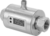 |
Also known as magmeters, these transmitters use a magnetic field to measure flow rate and temperature with high accuracy. Because they use a magnetic field, they only work with conductive liquids, such as water. These transmitters, also known as transducers, convert measurements to an electrical signal that can be interpreted by receiving devices, such as remote displays and programmable logic controllers (PLCs) to monitor flow or control equipment. For your receiving device to interpret the signal, you will need to calibrate it for the measurement range and output signal of the transmitter. As flow or temperature increases, the output signal increases. These transmitters have one analog output for flow and another for temperature. They only give accurate readings within the rated measurement range. A digital display makes it easy to view readings and adjust settings at the source. Mount these transmitters inline with your pipe system. They measure flow correctly in any mounting orientation.
These transmitters are calibrated with water. They can only be used with liquids with a conductivity of at least 20 µS/cm.
Flow Range | |||||||||||||||||||||||||||||||||||||||||||||||||||||||||||||||||||||||||||||||||||||||||||||||||||
|---|---|---|---|---|---|---|---|---|---|---|---|---|---|---|---|---|---|---|---|---|---|---|---|---|---|---|---|---|---|---|---|---|---|---|---|---|---|---|---|---|---|---|---|---|---|---|---|---|---|---|---|---|---|---|---|---|---|---|---|---|---|---|---|---|---|---|---|---|---|---|---|---|---|---|---|---|---|---|---|---|---|---|---|---|---|---|---|---|---|---|---|---|---|---|---|---|---|---|---|
Flow Measurement Type | Pipe Connections | Gallons per Minute, gpm | Liters per Minute, L/min | End-to-End Lg. | Accuracy | Max. Pressure @ Temp. | Temp. Range, ° F | Input Voltage Range, V DC | Mounting Position | Field Recalibratable | Enclosure Rating | Each | |||||||||||||||||||||||||||||||||||||||||||||||||||||||||||||||||||||||||||||||||||||||
Two 4-20 mA Analog Transmitter Outputs—4-Pole Micro M12 Connection Plugs | |||||||||||||||||||||||||||||||||||||||||||||||||||||||||||||||||||||||||||||||||||||||||||||||||||
316 Stainless Steel/Plastic/Polybutylene Body with 316 Stainless Steel Fitting | |||||||||||||||||||||||||||||||||||||||||||||||||||||||||||||||||||||||||||||||||||||||||||||||||||
| Magnetic Induction | 1 1/2 NPT Female | 1.3 to 79.3 | 5 to 300 | 6 11/16" | -0.8% to 0.8% | 225 psi @ 70° F | 0 to 175 | 20 to 30 | Any Angle | No | IP65, IP67 | 00000000 | 000000000 | ||||||||||||||||||||||||||||||||||||||||||||||||||||||||||||||||||||||||||||||||||||||
| Magnetic Induction | 2 NPT Female | 1.3 to 158.5 | 5 to 600 | 7 1/16" | -0.8% to 0.8% | 225 psi @ 70° F | 0 to 175 | 20 to 30 | Any Angle | No | IP65, IP67 | 00000000 | 00000000 | ||||||||||||||||||||||||||||||||||||||||||||||||||||||||||||||||||||||||||||||||||||||
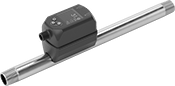
Insertion-Mount Flow and Temperature Transmitters
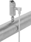 |
Thread mounting hardware (sold separately) into your pipe connection and insert the probe of these transmitters to measure the flow and temperature of water, oil, or air. The probe is held in place with a compression fitting on the other end of the mounting hardware. They’re often used in large-diameter pipes where it would be difficult to install a transmitter inline. To calculate the flow rate, these transmitters generate a small amount of heat, then measure the cooling effect your liquid or air has on it. They measure and output both flow and temperature, making them ideal for applications where temperature fluctuates. Also known as transducers, they convert measurements to an electrical signal that can be interpreted by receiving devices, such as remote displays and programmable logic controllers (PLCs) to monitor flow or control equipment. As flow or temperature increases, the output signal increases. For your receiving device to interpret the signal, you will need to calibrate it for the measurement range and output signal of the transmitter. They only give accurate readings within the rated measurement range. They’ll measure flow correctly in any mounting orientation. These transmitters are calibrated with air, glycol solutions, oil, and water but can be recalibrated in the field for other liquids.
Adjust settings at the source using the digital display. These transmitters have two configurable outputs. One can be wired for flow or temperature as an analog output or a digital switch. The other one can be wired for flow as a digital switch, digital pulse output, or IO Link. Pulse outputs send flow data using spikes of voltage that match the input voltage of the transmitter. The higher the flow, the more pulses they send. To change settings and receive error messages remotely from your PLC or computer, you can program one of the outputs to use IO Link. You’ll need an IO Link controller (not included) to connect to your interface.
Flow Measurement Type | Flow Range, gpm | Probe Lg. | End-to-End Lg. | Accuracy | Max. Pressure @ Temp. | Temp. Range, ° F | Input Voltage Range, V DC | Mounting Position | Field Recalibratable | Enclosure Rating | Each | ||||||||||||||||||||||||||||||||||||||||||||||||||||||||||||||||||||||||||||||||||||||||
|---|---|---|---|---|---|---|---|---|---|---|---|---|---|---|---|---|---|---|---|---|---|---|---|---|---|---|---|---|---|---|---|---|---|---|---|---|---|---|---|---|---|---|---|---|---|---|---|---|---|---|---|---|---|---|---|---|---|---|---|---|---|---|---|---|---|---|---|---|---|---|---|---|---|---|---|---|---|---|---|---|---|---|---|---|---|---|---|---|---|---|---|---|---|---|---|---|---|---|---|
One Digital Switch/Pulse Output and One 4-20 mA Analog Transmitter/Digital Switch/Pulse Output—4-Pole Micro M12 Connection Plug | |||||||||||||||||||||||||||||||||||||||||||||||||||||||||||||||||||||||||||||||||||||||||||||||||||
316 Stainless Steel/Polybutylene Body with 316 Stainless Steel Fitting | |||||||||||||||||||||||||||||||||||||||||||||||||||||||||||||||||||||||||||||||||||||||||||||||||||
| Thermal | 0.02 to 12 | 3 15/16" | 7 9/16" | -10% to 10% | 725 psi @ 212° F | 0 to 212 | 18 to 30 | Any Angle | Yes | IP65, IP67 | 00000000 | 0000000 | |||||||||||||||||||||||||||||||||||||||||||||||||||||||||||||||||||||||||||||||||||||||
| Thermal | 0.02 to 12 | 7 7/8" | 11 1/2" | -10% to 10% | 725 psi @ 212° F | 0 to 212 | 18 to 30 | Any Angle | Yes | IP65, IP67 | 00000000 | 000000 | |||||||||||||||||||||||||||||||||||||||||||||||||||||||||||||||||||||||||||||||||||||||
Flow, Pressure, and Temperature Transmitters for Gases
 |
Measure and transmit flow rate, pressure, and temperature of industrial gases, such as air, argon, CO2, and nitrogen, flowing through your system. These transmitters are ideal for applications where temperature and pressure can fluctuate. To calculate flow rate, they generate a small amount of heat, then measure the cooling effect your gas has on it. Also known as transducers, these transmitters convert measurements to an electrical signal that can be interpreted by receiving devices, such as remote displays and programmable logic controllers (PLCs). As flow, temperature, and pressure increases, the output signal increases. For your receiving device to interpret the signal, you will need to calibrate it for the measurement range and output signal of the transmitter. They only give accurate readings within the rated measurement range. Mount them directly inline with your system. They measure correctly no matter their mounting orientation.
A digital display makes it easy to read measurements and adjust settings based on your gas. These transmitters have two configurable outputs, and each output can only be wired for one measurement (flow rate, pressure, or temperature). Outputs configured as digital pulse send flow data using spikes of voltage that match the input voltage of the transmitter. One of the outputs can be wired for IO-Link, so you can change settings and receive error messages remotely from your PLC or computer. You’ll need an IO Link controller (not included) to connect to your interface.
These transmitters are calibrated with air but still measure accurately when used with other gases.
Flow Measurement Type | Pipe Connections | Flow Range, scfm | End-to-End Lg. | Accuracy | Max. Pressure @ Temp. | Temp. Range, ° F | Seal Material | Input Voltage Range, V DC | Mounting Position | Field Recalibratable | Enclosure Rating | Each | |||||||||||||||||||||||||||||||||||||||||||||||||||||||||||||||||||||||||||||||||||||||
|---|---|---|---|---|---|---|---|---|---|---|---|---|---|---|---|---|---|---|---|---|---|---|---|---|---|---|---|---|---|---|---|---|---|---|---|---|---|---|---|---|---|---|---|---|---|---|---|---|---|---|---|---|---|---|---|---|---|---|---|---|---|---|---|---|---|---|---|---|---|---|---|---|---|---|---|---|---|---|---|---|---|---|---|---|---|---|---|---|---|---|---|---|---|---|---|---|---|---|---|
One Digital Switch/Pulse Output and One 4-20 mA Analog Transmitter/Digital Switch/Pulse Output—4-Pole Micro M12 Connection Plug | |||||||||||||||||||||||||||||||||||||||||||||||||||||||||||||||||||||||||||||||||||||||||||||||||||
304 Stainless Steel Body with 304 Stainless Steel Fitting | |||||||||||||||||||||||||||||||||||||||||||||||||||||||||||||||||||||||||||||||||||||||||||||||||||
| Thermal | 1/2 NPT Male | 0.15 to 44 | 11 13/16" | -6% to 6% | 230 psi @ 70° F | 14 to 140 | Fluoroelastomer | 18 to 30 | Any Angle | No | IP65, IP67 | 0000000 | 0000000 | ||||||||||||||||||||||||||||||||||||||||||||||||||||||||||||||||||||||||||||||||||||||
| Thermal | 1 NPT Male | 0.4 to 132 | 18 3/4" | -6% to 6% | 230 psi @ 70° F | 14 to 140 | Fluoroelastomer | 18 to 30 | Any Angle | No | IP65, IP67 | 0000000 | 00000000 | ||||||||||||||||||||||||||||||||||||||||||||||||||||||||||||||||||||||||||||||||||||||
