


Filter by
Maximum Flow
For Use With
Calibrated With
Measures
Body Material
Minimum Flow
Wetted Parts Material
Flow Measurement Unit
Connects To
Fitting Material
Flow Measurement Type
Maximum Pressure @ Temperature
RoHS
Electrical Connection

Mounting Location
REACH
Output Current
Export Control Classification Number (ECCN)
DFARS Specialty Metals
Measurement Unit
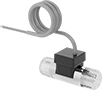
Flow Transmitters with Sight
 |
Flow Measurement Type | Pipe Connections | Flow Range, gpm | End-to-End Lg. | Accuracy | Max. Pressure @ Temp. | Temp. Range, ° F | Seal Material | Input Voltage Range, V DC | Mounting Position | Field Recalibratable | Pulse Freq., Hz | Pulse Frequency per Volume, pulse per gal. | Each | ||||||||||||||||||||||||||||||||||||||||||||||||||||||||||||||||||||||||||||||||||||||
|---|---|---|---|---|---|---|---|---|---|---|---|---|---|---|---|---|---|---|---|---|---|---|---|---|---|---|---|---|---|---|---|---|---|---|---|---|---|---|---|---|---|---|---|---|---|---|---|---|---|---|---|---|---|---|---|---|---|---|---|---|---|---|---|---|---|---|---|---|---|---|---|---|---|---|---|---|---|---|---|---|---|---|---|---|---|---|---|---|---|---|---|---|---|---|---|---|---|---|---|
One 4-20 mA Analog Transmitter Output—Wire Lead Connection | |||||||||||||||||||||||||||||||||||||||||||||||||||||||||||||||||||||||||||||||||||||||||||||||||||
Glass-Filled Polypropylene Body with Glass-Filled Polypropylene Fitting | |||||||||||||||||||||||||||||||||||||||||||||||||||||||||||||||||||||||||||||||||||||||||||||||||||
| Turbine | 1/2 NPT Female | 0.25 to 2.5 | 3 11/16" | ±2% | 150 psi @ 70° F | 20 to 150 | Buna-N | 12 to 24 | Any Angle | No | — | — | 00000000 | 0000000 | |||||||||||||||||||||||||||||||||||||||||||||||||||||||||||||||||||||||||||||||||||||
| Turbine | 1/2 NPT Female | 0.5 to 5 | 3 11/16" | ±2% | 150 psi @ 70° F | 20 to 150 | Buna-N | 12 to 24 | Any Angle | No | — | — | 00000000 | 000000 | |||||||||||||||||||||||||||||||||||||||||||||||||||||||||||||||||||||||||||||||||||||
| Turbine | 1/2 NPT Female | 1.5 to 15 | 3 11/16" | ±2% | 150 psi @ 70° F | 20 to 150 | Buna-N | 12 to 24 | Any Angle | No | — | — | 00000000 | 000000 | |||||||||||||||||||||||||||||||||||||||||||||||||||||||||||||||||||||||||||||||||||||
316 Stainless Steel Body with 316 Stainless Steel Fitting | |||||||||||||||||||||||||||||||||||||||||||||||||||||||||||||||||||||||||||||||||||||||||||||||||||
| Turbine | 1/2 NPT Female | 0.25 to 2.5 | 3 11/16" | ±2% | 200 psi @ 70° F | 20 to 212 | Buna-N | 12 to 24 | Any Angle | No | — | — | 00000000 | 00000000 | |||||||||||||||||||||||||||||||||||||||||||||||||||||||||||||||||||||||||||||||||||||
| Turbine | 1/2 NPT Female | 0.5 to 5 | 3 11/16" | ±2% | 200 psi @ 70° F | 20 to 212 | Buna-N | 12 to 24 | Any Angle | No | — | — | 00000000 | 00000000 | |||||||||||||||||||||||||||||||||||||||||||||||||||||||||||||||||||||||||||||||||||||
| Turbine | 1/2 NPT Female | 1.5 to 15 | 3 11/16" | ±2% | 200 psi @ 70° F | 20 to 212 | Buna-N | 12 to 24 | Any Angle | No | — | — | 00000000 | 00000000 | |||||||||||||||||||||||||||||||||||||||||||||||||||||||||||||||||||||||||||||||||||||
| Turbine | 3/4 NPT Female | 1.5 to 15 | 5 1/4" | ±2% | 200 psi @ 70° F | 20 to 212 | Buna-N | 12 to 24 | Any Angle | No | — | — | 00000000 | 00000000 | |||||||||||||||||||||||||||||||||||||||||||||||||||||||||||||||||||||||||||||||||||||
| Turbine | 3/4 NPT Female | 5 to 50 | 5 1/4" | ±2% | 200 psi @ 70° F | 20 to 212 | Buna-N | 12 to 24 | Any Angle | No | — | — | 00000000 | 00000000 | |||||||||||||||||||||||||||||||||||||||||||||||||||||||||||||||||||||||||||||||||||||
| Turbine | 1 NPT Female | 1.5 to 15 | 5 1/4" | ±2% | 200 psi @ 70° F | 20 to 212 | Buna-N | 12 to 24 | Any Angle | No | — | — | 00000000 | 00000000 | |||||||||||||||||||||||||||||||||||||||||||||||||||||||||||||||||||||||||||||||||||||
| Turbine | 1 NPT Female | 5 to 50 | 5 1/4" | ±2% | 200 psi @ 70° F | 20 to 212 | Buna-N | 12 to 24 | Any Angle | No | — | — | 00000000 | 00000000 | |||||||||||||||||||||||||||||||||||||||||||||||||||||||||||||||||||||||||||||||||||||
One 0-5V DC Analog Transmitter Output—Wire Lead Connection | |||||||||||||||||||||||||||||||||||||||||||||||||||||||||||||||||||||||||||||||||||||||||||||||||||
Glass-Filled Polypropylene Body with Glass-Filled Polypropylene Fitting | |||||||||||||||||||||||||||||||||||||||||||||||||||||||||||||||||||||||||||||||||||||||||||||||||||
| Turbine | 1/2 NPT Female | 0.25 to 2.5 | 3 11/16" | ±2% | 150 psi @ 70° F | 20 to 150 | Buna-N | 12 to 24 | Any Angle | No | — | — | 00000000 | 000000 | |||||||||||||||||||||||||||||||||||||||||||||||||||||||||||||||||||||||||||||||||||||
| Turbine | 1/2 NPT Female | 0.5 to 5 | 3 11/16" | ±2% | 150 psi @ 70° F | 20 to 150 | Buna-N | 12 to 24 | Any Angle | No | — | — | 00000000 | 000000 | |||||||||||||||||||||||||||||||||||||||||||||||||||||||||||||||||||||||||||||||||||||
| Turbine | 1/2 NPT Female | 1.5 to 15 | 3 11/16" | ±2% | 150 psi @ 70° F | 20 to 150 | Buna-N | 12 to 24 | Any Angle | No | — | — | 00000000 | 000000 | |||||||||||||||||||||||||||||||||||||||||||||||||||||||||||||||||||||||||||||||||||||
316 Stainless Steel Body with 316 Stainless Steel Fitting | |||||||||||||||||||||||||||||||||||||||||||||||||||||||||||||||||||||||||||||||||||||||||||||||||||
| Turbine | 1/2 NPT Female | 0.25 to 2.5 | 3 11/16" | ±2% | 200 psi @ 70° F | 20 to 212 | Buna-N | 12 to 24 | Any Angle | No | — | — | 00000000 | 000000 | |||||||||||||||||||||||||||||||||||||||||||||||||||||||||||||||||||||||||||||||||||||
| Turbine | 1/2 NPT Female | 0.5 to 5 | 3 11/16" | ±2% | 200 psi @ 70° F | 20 to 212 | Buna-N | 12 to 24 | Any Angle | No | — | — | 00000000 | 000000 | |||||||||||||||||||||||||||||||||||||||||||||||||||||||||||||||||||||||||||||||||||||
| Turbine | 1/2 NPT Female | 1.5 to 15 | 3 11/16" | ±2% | 200 psi @ 70° F | 20 to 212 | Buna-N | 12 to 24 | Any Angle | No | — | — | 00000000 | 000000 | |||||||||||||||||||||||||||||||||||||||||||||||||||||||||||||||||||||||||||||||||||||
| Turbine | 3/4 NPT Female | 1.5 to 15 | 5 1/4" | ±2% | 200 psi @ 70° F | 20 to 212 | Buna-N | 12 to 24 | Any Angle | No | — | — | 00000000 | 00000000 | |||||||||||||||||||||||||||||||||||||||||||||||||||||||||||||||||||||||||||||||||||||
| Turbine | 3/4 NPT Female | 5 to 50 | 5 1/4" | ±2% | 200 psi @ 70° F | 20 to 212 | Buna-N | 12 to 24 | Any Angle | No | — | — | 00000000 | 00000000 | |||||||||||||||||||||||||||||||||||||||||||||||||||||||||||||||||||||||||||||||||||||
| Turbine | 1 NPT Female | 1.5 to 15 | 5 1/4" | ±2% | 200 psi @ 70° F | 20 to 212 | Buna-N | 12 to 24 | Any Angle | No | — | — | 00000000 | 00000000 | |||||||||||||||||||||||||||||||||||||||||||||||||||||||||||||||||||||||||||||||||||||
| Turbine | 1 NPT Female | 5 to 50 | 5 1/4" | ±2% | 200 psi @ 70° F | 20 to 212 | Buna-N | 12 to 24 | Any Angle | No | — | — | 00000000 | 00000000 | |||||||||||||||||||||||||||||||||||||||||||||||||||||||||||||||||||||||||||||||||||||
One Digital Pulse Output—Wire Lead Connection | |||||||||||||||||||||||||||||||||||||||||||||||||||||||||||||||||||||||||||||||||||||||||||||||||||
Polypropylene Body with Polypropylene Fitting | |||||||||||||||||||||||||||||||||||||||||||||||||||||||||||||||||||||||||||||||||||||||||||||||||||
| Turbine | 1/4 NPT Female | 0.1 to 5 | 3 1/16" | ±7% | 100 psi @ 70° F | 33 to 180 | Fluoroelastomer | 4.25 to 24 | Any Angle | No | 15 to 225 | — | 0000000 | 000000 | |||||||||||||||||||||||||||||||||||||||||||||||||||||||||||||||||||||||||||||||||||||
| Turbine | 1/2 NPT Female | 1.5 to 20 | 3 1/16" | ±15% | 100 psi @ 70° F | 33 to 180 | Fluoroelastomer | 4.25 to 24 | Any Angle | No | 15 to 225 | — | 0000000 | 000000 | |||||||||||||||||||||||||||||||||||||||||||||||||||||||||||||||||||||||||||||||||||||
Brass Body with Brass Fitting | |||||||||||||||||||||||||||||||||||||||||||||||||||||||||||||||||||||||||||||||||||||||||||||||||||
| Turbine | 1/4 NPT Female | 0.1 to 5 | 3" | ±7% | 200 psi @ 70° F | 33 to 212 | Fluoroelastomer | 4.5 to 24 | Any Angle | No | 15 to 225 | — | 0000000 | 000000 | |||||||||||||||||||||||||||||||||||||||||||||||||||||||||||||||||||||||||||||||||||||
| Turbine | 1/2 NPT Female | 1.5 to 20 | 3" | ±15% | 200 psi @ 70° F | 33 to 212 | Fluoroelastomer | 4.5 to 24 | Any Angle | No | 15 to 225 | — | 0000000 | 000000 | |||||||||||||||||||||||||||||||||||||||||||||||||||||||||||||||||||||||||||||||||||||
| Turbine | 1 NPT Female | 8 to 60 | 3 15/16" | ±15% | 200 psi @ 70° F | 33 to 212 | Fluoroelastomer | 4.5 to 24 | Any Angle | No | 15 to 225 | — | 0000000 | 000000 | |||||||||||||||||||||||||||||||||||||||||||||||||||||||||||||||||||||||||||||||||||||
316 Stainless Steel Body with 316 Stainless Steel Fitting | |||||||||||||||||||||||||||||||||||||||||||||||||||||||||||||||||||||||||||||||||||||||||||||||||||
| Turbine | 1/2 NPT Female | 0.25 to 2.5 | 3 11/16" | ±2% | 200 psi @ 70° F | 20 to 212 | Buna-N | 12 to 24 | Any Angle | No | — | 200 | 00000000 | 000000 | |||||||||||||||||||||||||||||||||||||||||||||||||||||||||||||||||||||||||||||||||||||
| Turbine | 1/2 NPT Female | 1.5 to 20 | 3" | ±15% | 200 psi @ 70° F | 33 to 212 | Fluoroelastomer | 4.5 to 24 | Any Angle | No | 15 to 225 | — | 0000000 | 000000 | |||||||||||||||||||||||||||||||||||||||||||||||||||||||||||||||||||||||||||||||||||||
| Turbine | 3/4 NPT Female | 5 to 30 | 3 15/16" | ±15% | 200 psi @ 70° F | 33 to 212 | Fluoroelastomer | 4.5 to 24 | Any Angle | No | 15 to 225 | — | 0000000 | 000000 | |||||||||||||||||||||||||||||||||||||||||||||||||||||||||||||||||||||||||||||||||||||
| Turbine | 1 NPT Female | 8 to 60 | 3 15/16" | ±15% | 200 psi @ 70° F | 33 to 212 | Fluoroelastomer | 4.5 to 24 | Any Angle | No | 15 to 225 | — | 0000000 | 000000 | |||||||||||||||||||||||||||||||||||||||||||||||||||||||||||||||||||||||||||||||||||||
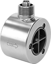
Flow Transmitters
 |
Turbine Flow Measurement |
Flow Measurement Type | Pipe Connections | Flow Range, gpm | End-to-End Lg. | Accuracy | Max. Pressure @ Temp. | Temp. Range, ° F | Input Voltage Range, V DC | Mounting Position | Field Recalibratable | Pulse Freq., Hz | Each | ||||||||||||||||||||||||||||||||||||||||||||||||||||||||||||||||||||||||||||||||||||||||
|---|---|---|---|---|---|---|---|---|---|---|---|---|---|---|---|---|---|---|---|---|---|---|---|---|---|---|---|---|---|---|---|---|---|---|---|---|---|---|---|---|---|---|---|---|---|---|---|---|---|---|---|---|---|---|---|---|---|---|---|---|---|---|---|---|---|---|---|---|---|---|---|---|---|---|---|---|---|---|---|---|---|---|---|---|---|---|---|---|---|---|---|---|---|---|---|---|---|---|---|
One Analog Transmitter/Digital Pulse Output—Wire Lead Connection | |||||||||||||||||||||||||||||||||||||||||||||||||||||||||||||||||||||||||||||||||||||||||||||||||||
Nylon Body with Nylon Fitting | |||||||||||||||||||||||||||||||||||||||||||||||||||||||||||||||||||||||||||||||||||||||||||||||||||
| Turbine | 1/4 NPT Male | 0.026 to 0.65 | 1 3/4" | ±3% | 362 psi @ 212° F | -4 to 212 | 5 to 24 | Any Angle | No | 36 to 902 | 00000000 | 0000000 | |||||||||||||||||||||||||||||||||||||||||||||||||||||||||||||||||||||||||||||||||||||||
| Turbine | 3/8 NPT Male | 0.13 to 1.3 | 2 5/32" | ±3% | 362 psi @ 212° F | -4 to 212 | 5 to 24 | Any Angle | No | 56 to 565 | 00000000 | 000000 | |||||||||||||||||||||||||||||||||||||||||||||||||||||||||||||||||||||||||||||||||||||||
| Turbine | 3/8 NPT Male | 0.26 to 4 | 2 5/32" | ±3% | 362 psi @ 212° F | -4 to 212 | 5 to 24 | Any Angle | No | 36 to 553 | 00000000 | 000000 | |||||||||||||||||||||||||||||||||||||||||||||||||||||||||||||||||||||||||||||||||||||||
| Turbine | 3/8 NPT Male | 0.53 to 9.2 | 2 5/32" | ±3% | 362 psi @ 212° F | -4 to 212 | 5 to 24 | Any Angle | No | 25 to 435 | 00000000 | 000000 | |||||||||||||||||||||||||||||||||||||||||||||||||||||||||||||||||||||||||||||||||||||||
| Turbine | 3/4 NPT Male | 1.32 to 17.17 | 2 15/16" | ±3% | 362 psi @ 212° F | -4 to 212 | 5 to 24 | Any Angle | No | 17 to 227 | 00000000 | 000000 | |||||||||||||||||||||||||||||||||||||||||||||||||||||||||||||||||||||||||||||||||||||||
Brass Body with Brass Fitting | |||||||||||||||||||||||||||||||||||||||||||||||||||||||||||||||||||||||||||||||||||||||||||||||||||
| Turbine | 3/8 NPT Male | 0.5 to 2.11 | 2 5/32" | ±3% | 362 psi @ 212° F | -4 to 212 | 5 to 24 | Any Angle | No | 132 to 559 | 00000000 | 000000 | |||||||||||||||||||||||||||||||||||||||||||||||||||||||||||||||||||||||||||||||||||||||
| Turbine | 3/8 NPT Male | 0.8 to 6.6 | 2 5/32" | ±3% | 362 psi @ 212° F | -4 to 212 | 5 to 24 | Any Angle | No | 46 to 383 | 00000000 | 000000 | |||||||||||||||||||||||||||||||||||||||||||||||||||||||||||||||||||||||||||||||||||||||
Build-Your-Own Flanged Pipe Flow Transmitters
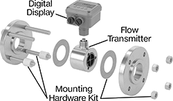 |
Components Sold Separately (Pipe Flanges Not Included) |
Flow Transmitters
 |
Flange | |||||||||||||||||||||||||||||||||||||||||||||||||||||||||||||||||||||||||||||||||||||||||||||||||||
|---|---|---|---|---|---|---|---|---|---|---|---|---|---|---|---|---|---|---|---|---|---|---|---|---|---|---|---|---|---|---|---|---|---|---|---|---|---|---|---|---|---|---|---|---|---|---|---|---|---|---|---|---|---|---|---|---|---|---|---|---|---|---|---|---|---|---|---|---|---|---|---|---|---|---|---|---|---|---|---|---|---|---|---|---|---|---|---|---|---|---|---|---|---|---|---|---|---|---|---|
Flow Measurement Type | Pipe Size | Flow Range, gpm | Bore Size | OD | Type | For Flange ANSI Class | End-to-End Lg. | Accuracy | Max. Pressure @ Temp. | Temp. Range, ° F | Mounting Position | Field Recalibratable | Pulse Frequency per Volume, pulse per gal. | Each | |||||||||||||||||||||||||||||||||||||||||||||||||||||||||||||||||||||||||||||||||||||
One Digital Pulse Output—2-Pin BNC Connection Plug | |||||||||||||||||||||||||||||||||||||||||||||||||||||||||||||||||||||||||||||||||||||||||||||||||||
316/316L Stainless Steel Body with 316/316L Stainless Steel Fitting | |||||||||||||||||||||||||||||||||||||||||||||||||||||||||||||||||||||||||||||||||||||||||||||||||||
| Turbine | 1 | 3 to 30 | 7/8" | 2" | Round | 150 | 4" | ±1.0% | 285 psi @ 70° F | -150 to 350 | Any Angle | No | 3,100 | 0000000 | 0000000 | ||||||||||||||||||||||||||||||||||||||||||||||||||||||||||||||||||||||||||||||||||||
| Turbine | 2 | 5 to 50 | 1" | 3 5/8" | Round | 150 | 2 1/2" | ±1.0% | 285 psi @ 70° F | -150 to 350 | Any Angle | No | 850 | 0000000 | 00000000 | ||||||||||||||||||||||||||||||||||||||||||||||||||||||||||||||||||||||||||||||||||||
| Turbine | 2 | 15 to 180 | 1 1/2" | 3 5/8" | Round | 150 | 2 1/2" | ±1.0% | 285 psi @ 70° F | -150 to 350 | Any Angle | No | 325 | 0000000 | 00000000 | ||||||||||||||||||||||||||||||||||||||||||||||||||||||||||||||||||||||||||||||||||||
| Turbine | 3 | 60 to 600 | 3" | 5" | Round | 150 | 4 1/4" | ±1.0% | 285 psi @ 70° F | -150 to 350 | Any Angle | No | 50 | 0000000 | 00000000 | ||||||||||||||||||||||||||||||||||||||||||||||||||||||||||||||||||||||||||||||||||||
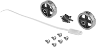 |
For Pipe Size | For Bore Size | For Flange ANSI Class | Includes | Each | ||
|---|---|---|---|---|---|---|
| 1 | 7/8" | 150 | 6 Screws, 2 Rotor Supports, One Rotor Assembly, One K-Factor Tag | 0000000 | 0000000 | |
| 2 | 1" | 150 | 6 Screws, 2 Rotor Supports, One Rotor Assembly, One K-Factor Tag | 0000000 | 000000 | |
| 2 | 1 1/2" | 150 | 6 Screws, 2 Rotor Supports, One Rotor Assembly, One K-Factor Tag | 0000000 | 000000 | |
| 3 | 3" | 150 | 6 Screws, 2 Rotor Supports, One Rotor Assembly, One K-Factor Tag | 0000000 | 00000000 |
