


About Flowmeters and Totalizers
Flowmeters measure the rate of flow for a liquid or a gas. Totalizers measure the cumulative flow volume. Flowmeter/totalizers display both the flow rate and the cumulative flow volume.
More
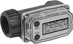
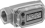
Flowmeter/Totalizers
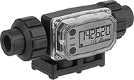
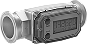
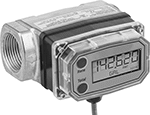
Determine the flow rate and total volume of liquid flowing through your system with the same meter. To measure flow, these flowmeter/totalizers count how many times their turbine turns as liquid passes through. Use them only with clean, low-viscosity liquids to avoid clogging the turbine and other damage to these flowmeter/totalizers. You can reset the batch total, but you can’t reset the cumulative total. Mount them inline with your pipe system. They’re accurate in any mounting orientation.
These flowmeter/totalizers are either calibrated with water or solvent. You can recalibrate them in the field to other liquids, pipe, and operating conditions.
Choose a fitting material that is compatible with the liquid you're running through your line. PVC, nylon, and PVDF plastic fittings work with a wide range of chemicals. However, they can crack from impact or when overtightened. 316 stainless steel fittings resist impact better than plastic fittings.
Flowmeter/totalizers with a calibration certificate traceable to NIST include documentation that states they’ve passed a test for accuracy.
IP rated, all seal out dust and can be lightly rinsed. NEMA 4 flowmeter/totalizers protect against weather and washdowns. FM-approved flowmeter/totalizers are safe for use in hazardous location.
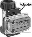
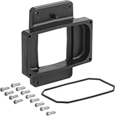
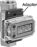
90° display adapter kits let you rotate the meter’s display 90°, so you can read it easier when mounted vertically.
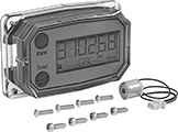
Output modules allow you to transmit flow data from flowmeter/totalizers to an external device such as a programmable logic controller (PLC), data recorder, logger, and remote display (not included). 4-20 mA output modules have an analog output. As flow increases, the output signal from the transmitter increases. For your receiving device to interpret the signal from the transmitter, you will need to calibrate it for the measurement range and output signal of the transmitter. They only give accurate readings within the rated measurement range. Pulse output modules have a digital output. They transmit flow data using spikes of voltage that match the input voltage of the transmitter. The higher the flow, the more pulses they send.
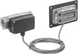
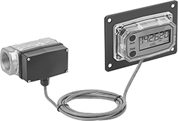
Remote panel-mounting kits let you mount the meter’s display up to 10 feet away.
Flowmeter/Totalizers | 90° Display Adapter Kits | ||||||||||||||
|---|---|---|---|---|---|---|---|---|---|---|---|---|---|---|---|
| Pipe Connections | Flow Range, gpm | Pipe Schedule | End-to-End Lg. | Accuracy | Max. Total Volume, gallons | Max. Batch Volume, gallons | Max. Pressure | Temp. Range, °F | Batteries Included | Environmental Rating | Specifications Met | Each | Each | ||
Flowmeter/Totalizers | |||||||||||||||
| 1 NPT Female | 0.3 to 3 | 80 | 4" | ±1.5% | 999,999 | 999,999 | 150 psi @ 70 ° F | 14° to 140° | Yes | IP65 NEMA 4 NEC Class I Divisions 1, 2 Groups A, B, C, D; NEC Class II Divisions 1, 2 Groups E, F, G; NEC Class III Divisions 1, 2; | FM Approved, AEx ia IIC T4 | 00000000 | 0000000 | 00000000 | 000000 |
Flowmeter/Totalizers with Calibration Certificate Traceable to NIST | |||||||||||||||
| 1 NPT Female | 0.3 to 3 | 80 | 4" | ±1.5% | 999,999 | 999,999 | 150 psi @ 70 ° F | 14° to 140° | Yes | IP65 NEMA 4 NEC Class I Divisions 1, 2 Groups A, B, C, D; NEC Class II Divisions 1, 2 Groups E, F, G; NEC Class III Divisions 1, 2; | FM Approved, AEx ia IIC T4 | 00000000 | 000000 | 00000000 | 00000 |
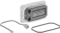
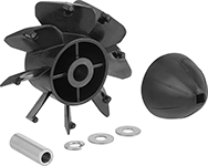
Flowmeter/Totalizers | Replacement Displays | Replacement Rotor Kits | |||||||||||||||
|---|---|---|---|---|---|---|---|---|---|---|---|---|---|---|---|---|---|
| Pipe Connections | Flow Range, gpm | Pipe Schedule | End-to-End Lg. | Accuracy | Max. Total Volume, gallons | Max. Batch Volume, gallons | Max. Pressure | Temp. Range, °F | Batteries Included | Environmental Rating | Specifications Met | Each | Each | Each | |||
Flowmeter/Totalizers | |||||||||||||||||
| 1/2 NPT Female | 1.2 to 12 | 80 | 7 5/16" | ±2% | 999,999 | 999,999 | 100 psi @ 70 ° F | 0° to 125° | Yes | IP65 NEMA 4 NEC Class I Divisions 1, 2 Groups A, B, C, D; | FM Approved, AEx ia IIC T4 | 00000000 | 000000000 | 00000000 | 0000000 | 00000000 | 0000000 |
| 1 NPT Female | 5 to 50 | 80 | 8 1/16" | ±1.5% | 999,999 | 999,999 | 100 psi @ 70 ° F | 0° to 125° | Yes | IP65 NEMA 4 NEC Class I Divisions 1, 2 Groups A, B, C, D; | FM Approved, AEx ia IIC T4 | 00000000 | 00000000 | 00000000 | 000000 | 00000000 | 000000 |
Flowmeter/Totalizers with Calibration Certificate Traceable to NIST | |||||||||||||||||
| 1/2 NPT Female | 1.2 to 12 | 80 | 7 5/16" | ±2% | 999,999 | 999,999 | 100 psi @ 70 ° F | 0° to 125° | Yes | IP65 NEMA 4 NEC Class I Divisions 1, 2 Groups A, B, C, D; | FM Approved, AEx ia IIC T4 | 00000000 | 000000 | 00000000 | 000000 | 00000000 | 000000 |
Flowmeter/Totalizers | Replacement Displays | 90° Display Adapter Kits | ||||||||||||||
|---|---|---|---|---|---|---|---|---|---|---|---|---|---|---|---|---|
| Pipe Connections | Flow Range, gpm | End-to-End Lg. | Accuracy | Max. Total Volume, gallons | Max. Batch Volume, gallons | Max. Pressure | Temp. Range, °F | Batteries Included | Environmental Rating | Specifications Met | Each | Each | Each | |||
Flowmeter/Totalizers | ||||||||||||||||
| 1/2 NPT Female | 1 to 10 | 4 1/4" | ±1.5% | 999,999 | 999,999 | 1500 psi @ 70 ° F | 14° to 140° | Yes | NEC Class I Divisions 1, 2 Groups A, B, C, D; NEC Class II Divisions 1, 2 Groups E, F, G; NEC Class III Divisions 1, 2; IP65 | FM Approved, CE Marked, ATEX II 1 G Ex ia IIC T4 Ga, C-FM Approved, IECEx Ex ia IIC T4 Ga | 00000000 | 0000000 | 00000000 | 0000000 | 00000000 | 000000 |
| 3/4 NPT Female | 2 to 20 | 4 3/8" | ±1% | 999,999 | 999,999 | 1500 psi @ 70 ° F | 14° to 140° | Yes | NEC Class I Divisions 1, 2 Groups A, B, C, D; NEC Class II Divisions 1, 2 Groups E, F, G; NEC Class III Divisions 1, 2; IP65 | FM Approved, CE Marked, ATEX II 1 G Ex ia IIC T4 Ga, C-FM Approved, IECEx Ex ia IIC T4 Ga | 00000000 | 000000 | 00000000 | 000000 | 00000000 | 00000 |
| 1 NPT Female | 5 to 50 | 4 1/2" | ±1% | 999,999 | 999,999 | 1500 psi @ 70 ° F | 14° to 140° | Yes | NEC Class I Divisions 1, 2 Groups A, B, C, D; NEC Class II Divisions 1, 2 Groups E, F, G; NEC Class III Divisions 1, 2; IP65 | FM Approved, CE Marked, ATEX II 1 G Ex ia IIC T4 Ga, C-FM Approved, IECEx Ex ia IIC T4 Ga | 00000000 | 000000 | 00000000 | 000000 | 00000000 | 00000 |
| 1 1/2 NPT Female | 10 to 100 | 5 3/8" | ±0.75% | 999,999 | 999,999 | 1500 psi @ 70 ° F | 14° to 140° | Yes | NEC Class I Divisions 1, 2 Groups A, B, C, D; NEC Class II Divisions 1, 2 Groups E, F, G; NEC Class III Divisions 1, 2; IP65 | FM Approved, CE Marked, ATEX II 1 G Ex ia IIC T4 Ga, C-FM Approved, IECEx Ex ia IIC T4 Ga | 00000000 | 00000000 | 00000000 | 000000 | 00000000 | 00000 |
| 2 NPT Female | 20 to 200 | 6 3/8" | ±0.75% | 999,999 | 999,999 | 1500 psi @ 70 ° F | 14° to 140° | Yes | NEC Class I Divisions 1, 2 Groups A, B, C, D; NEC Class II Divisions 1, 2 Groups E, F, G; NEC Class III Divisions 1, 2; IP65 | FM Approved, CE Marked, ATEX II 1 G Ex ia IIC T4 Ga, C-FM Approved, IECEx Ex ia IIC T4 Ga | 00000000 | 00000000 | 00000000 | 000000 | 00000000 | 00000 |
Flowmeter/Totalizers with Calibration Certificate Traceable to NIST | ||||||||||||||||
| 1/2 NPT Female | 1 to 10 | 4 1/4" | ±1.5% | 999,999 | 999,999 | 1500 psi @ 70 ° F | 14° to 140° | Yes | NEC Class I Divisions 1, 2 Groups A, B, C, D; NEC Class II Divisions 1, 2 Groups E, F, G; NEC Class III Divisions 1, 2; IP65 | FM Approved, CE Marked, ATEX II 1 G Ex ia IIC T4 Ga, C-FM Approved, IECEx Ex ia IIC T4 Ga | 00000000 | 00000000 | 00000000 | 000000 | 00000000 | 00000 |
| 3/4 NPT Female | 2 to 20 | 4 3/8" | ±1% | 999,999 | 999,999 | 1500 psi @ 70 ° F | 14° to 140° | Yes | NEC Class I Divisions 1, 2 Groups A, B, C, D; NEC Class II Divisions 1, 2 Groups E, F, G; NEC Class III Divisions 1, 2; IP65 | FM Approved, CE Marked, ATEX II 1 G Ex ia IIC T4 Ga, C-FM Approved, IECEx Ex ia IIC T4 Ga | 00000000 | 00000000 | 00000000 | 000000 | 00000000 | 00000 |
| 1 NPT Female | 5 to 50 | 4 1/2" | ±1% | 999,999 | 999,999 | 1500 psi @ 70 ° F | 14° to 140° | Yes | NEC Class I Divisions 1, 2 Groups A, B, C, D; NEC Class II Divisions 1, 2 Groups E, F, G; NEC Class III Divisions 1, 2; IP65 | FM Approved, CE Marked, ATEX II 1 G Ex ia IIC T4 Ga, C-FM Approved, IECEx Ex ia IIC T4 Ga | 00000000 | 00000000 | 00000000 | 000000 | 00000000 | 00000 |
| 1 1/2 NPT Female | 10 to 100 | 5 3/8" | ±0.75% | 999,999 | 999,999 | 1500 psi @ 70 ° F | 14° to 140° | Yes | NEC Class I Divisions 1, 2 Groups A, B, C, D; NEC Class II Divisions 1, 2 Groups E, F, G; NEC Class III Divisions 1, 2; IP65 | FM Approved, CE Marked, ATEX II 1 G Ex ia IIC T4 Ga, C-FM Approved, IECEx Ex ia IIC T4 Ga | 00000000 | 00000000 | 00000000 | 000000 | 00000000 | 00000 |
| 2 NPT Female | 20 to 200 | 6 3/8" | ±0.75% | 999,999 | 999,999 | 1500 psi @ 70 ° F | 14° to 140° | Yes | NEC Class I Divisions 1, 2 Groups A, B, C, D; NEC Class II Divisions 1, 2 Groups E, F, G; NEC Class III Divisions 1, 2; IP65 | FM Approved, CE Marked, ATEX II 1 G Ex ia IIC T4 Ga, C-FM Approved, IECEx Ex ia IIC T4 Ga | 00000000 | 00000000 | 00000000 | 000000 | 00000000 | 00000 |
| Component | Number of Wire Leads | Wire Lead Lg., ft. | Input Voltage Range | Includes | Pkg. Qty. | For Flow Measurement Type | Each | |
| 4-20 mA Output Module | 4 | 10 | 8V DC to 26V DC | __ | __ | Turbine | 00000000 | 0000000 |
| Remote Panel-Mounting Kit | __ | __ | __ | __ | __ | Turbine | 00000000 | 000000 |
| 90° Display Adapter Kits | __ | __ | __ | 12 Screws, 90° Display Adapter, Nitrile Rubber O-Ring | __ | Turbine | 00000000 | 00000 |
| Pkg. | ||||||||
|---|---|---|---|---|---|---|---|---|
| Disposable Batteries | __ | __ | __ | __ | 4 | __ | 00000000 | 0000 |
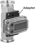
Flowmeter/Totalizers with Sanitary Quick-Clamp Fittings
Easy to remove for cleaning and maintenance, these flowmeter/totalizers connect to sanitary quick-clamp fittings (often called tri-clamp fittings) and measure the flow rate and volume of liquid passing through your system. You'll need a gasket and clamp (not included) to connect these to your line. They count how many times their turbine turns as liquid passes through to measure flow. To avoid clogging the turbine and other damage to the sensor, use them only with clean, low-viscosity liquids. You can reset the batch total, but you can't reset the cumulative total. Mount them directly inline with your piping system. They measure flow correctly no matter the mounting orientation.
For use in hazardous locations, these flowmeter/totalizers are FM-approved. They’re also rated NEMA 4 to protect against weather and washdowns.
These flowmeter/totalizers are calibrated with either water or solvent. You can recalibrate them in the field to other liquids, pipe, and operating conditions.
Flowmeter/totalizers with a calibration certificate traceable to NIST states that the flowmeter/totalizer has passed a test for accuracy.
90° display adapter kits let you rotate the meter’s display 90°, so you can read it easier when mounted vertically.
Flowmeter/Totalizers | Replacement Displays | ||||||||||||
|---|---|---|---|---|---|---|---|---|---|---|---|---|---|
| For Tube OD | Gender | Flow Range, gpm | Flange OD | End-to-End Lg. | Accuracy | Max. Total Volume, gallons | Max. Batch Volume, gallons | Max. Pressure | Temp. Range, °F | Each | Each | ||
Flowmeter/Totalizers | |||||||||||||
316 Stainless Steel Body with 316 Stainless Steel Fittings | |||||||||||||
| 3/4" | Female | 1 to 10 | 0.984" | 5" | ±1.5% | 999,999 | 999,999 | 1500 psi @ 70 ° F | 14° to 140° | 0000000 | 000000000 | 00000000 | 0000000 |
| 1" | Female | 2 to 20 | 1.984" | 5" | ±1% | 999,999 | 999,999 | 1500 psi @ 70 ° F | 14° to 140° | 0000000 | 00000000 | 00000000 | 000000 |
| 1 1/2" | Female | 5 to 50 | 1.984" | 5 1/2" | ±1% | 999,999 | 999,999 | 1500 psi @ 70 ° F | 14° to 140° | 0000000 | 00000000 | 00000000 | 000000 |
| 2" | Female | 10 to 100 | 2.515" | 6 1/2" | ±0.75% | 999,999 | 999,999 | 1500 psi @ 70 ° F | 14° to 140° | 0000000 | 00000000 | 00000000 | 000000 |
| 2 1/2" | Female | 20 to 200 | 3.047" | 7" | ±0.75% | 999,999 | 999,999 | 1500 psi @ 70 ° F | 14° to 140° | 0000000 | 00000000 | 00000000 | 000000 |
Flowmeter/Totalizers with Certificate of Calibration Traceable to NIST | |||||||||||||
316 Stainless Steel Body with 316 Stainless Steel Fittings | |||||||||||||
| 3/4" | Female | 1 to 10 | 0.984" | 5" | ±1.5% | 999,999 | 999,999 | 1500 psi @ 70 ° F | 14° to 140° | 0000000 | 00000000 | 00000000 | 000000 |
| 1" | Female | 2 to 20 | 1.984" | 5" | ±1% | 999,999 | 999,999 | 1500 psi @ 70 ° F | 14° to 140° | 0000000 | 00000000 | 00000000 | 000000 |
| 1 1/2" | Female | 5 to 50 | 1.984" | 5 1/2" | ±1% | 999,999 | 999,999 | 1500 psi @ 70 ° F | 14° to 140° | 0000000 | 00000000 | 00000000 | 000000 |
| 2" | Female | 10 to 100 | 2.515" | 6 1/2" | ±0.75% | 999,999 | 999,999 | 1500 psi @ 70 ° F | 14° to 140° | 0000000 | 00000000 | 00000000 | 000000 |
| 2 1/2" | Female | 20 to 200 | 3.047" | 7" | ±0.75% | 999,999 | 999,999 | 1500 psi @ 70 ° F | 14° to 140° | 0000000 | 00000000 | 00000000 | 000000 |
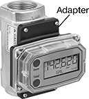
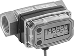
Flowmeter/Totalizers for Oil and Fuel
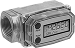
Use these flowmeter/totalizers to measure both the flow rate and total flow volume of oil, gasoline, diesel fuel, and kerosene. They count how many times their turbine turns as liquid passes through them to measure flow. To avoid clogging the turbine and other damage to the sensor, use them only with clean, low-viscosity liquids. You can reset the batch total, but you can't reset the cumulative total. Mount them directly inline with your piping system. They measure flow correctly no matter the mounting orientation. Rated NEMA 4 and IP65, they seal out dust and protect against washdowns.
These flowmeter/totalizers are calibrated with either water or solvent. You can recalibrate them in the field to other liquids, pipe, and operating conditions.
Flowmeter/totalizers with a calibration certificate traceable to NIST states that the flowmeter/totalizer has passed a test for accuracy.
Output modules allow you to transmit flow data from flowmeter/totalizers to an external device such as a programmable logic controller (PLC), data recorder, logger, and remote display (not included). 4-20 mA output modules have an analog output. As flow increases, the output signal from the transmitter increases. For your receiving device to interpret the signal from the transmitter, you will need to calibrate it for the measurement range and output signal of the transmitter. They only give accurate readings within the rated measurement range. Pulse output modules have a digital output. They transmit flow data using spikes of voltage that match the input voltage of the transmitter. The higher the flow, the more pulses they send.
Remote panel-mounting kits let you mount the meter’s display up to 10 feet away.
90° display adapter kits let you rotate the meter’s display 90°, so you can read it easier when mounted vertically.
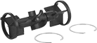
Flowmeter/Totalizers | Replacement Displays | Replacement Rotor Kits | ||||||||||||
|---|---|---|---|---|---|---|---|---|---|---|---|---|---|---|
| Pipe Connections | Flow Range, gpm | End-to-End Lg. | Accuracy | Max. Total Volume, gallons | Max Batch Volume, gallons | Max. Pressure | Mounting Orientation | Batteries Included | Each | Each | Each | |||
Flowmeter/Totalizers | ||||||||||||||
| 1/2 NPT Female | 1 to 10 | 4 3/16" | ±2% | 999,999 | 999,999 | 300 psi @ 70 ° F | Any | Yes | 00000000 | 0000000 | 00000000 | 0000000 | 00000000 | 0000000 |
| 3/4 NPT Female | 2 to 20 | 4 5/16" | ±1.5% | 999,999 | 999,999 | 300 psi @ 70 ° F | Any | Yes | 00000000 | 000000 | 00000000 | 000000 | 00000000 | 000000 |
| 1 NPT Female | 0.3 to 3 | 4" | ±5% | 999,999 | 999,999 | 300 psi @ 70 ° F | Any | Yes | 00000000 | 000000 | 000000 | 00 | 000000 | 00 |
| 1 NPT Female | 3 to 50 | 4" | ±1.5% | 999,999 | 999,999 | 300 psi @ 70 ° F | Any | Yes | 00000000 | 000000 | 000000 | 00 | 000000 | 00 |
| 1 1/2 NPT Female | 10 to 100 | 5 5/16" | ±1% | 999,999 | 999,999 | 300 psi @ 70 ° F | Any | Yes | 00000000 | 00000000 | 00000000 | 000000 | 00000000 | 000000 |
| 2 NPT Female | 20 to 200 | 6" | ±0.75% | 999,999 | 999,999 | 300 psi @ 70 ° F | Any | Yes | 0000000 | 00000000 | 000000 | 000000 | 000000 | 00 |
Flowmeter/Totalizers with Calibration Certificate Traceable to NIST | ||||||||||||||
| 1/2 NPT Female | 1 to 10 | 4 3/16" | ±2% | 999,999 | 999,999 | 300 psi @ 70 ° F | Any | Yes | 00000000 | 00000000 | 00000000 | 000000 | 00000000 | 000000 |
| 3/4 NPT Female | 2 to 20 | 4 5/16" | ±1.5% | 999,999 | 999,999 | 300 psi @ 70 ° F | Any | Yes | 00000000 | 00000000 | 00000000 | 000000 | 00000000 | 000000 |
| 1 NPT Female | 0.3 to 3 | 4" | ±5% | 999,999 | 999,999 | 300 psi @ 70 ° F | Any | Yes | 00000000 | 000000 | 000000 | 00 | 000000 | 00 |
| 1 NPT Female | 3 to 50 | 4" | ±1.5% | 999,999 | 999,999 | 300 psi @ 70 ° F | Any | Yes | 00000000 | 000000 | 000000 | 00 | 000000 | 00 |
| 1 1/2 NPT Female | 10 to 100 | 5 5/16" | ±1% | 999,999 | 999,999 | 300 psi @ 70 ° F | Any | Yes | 00000000 | 00000000 | 00000000 | 000000 | 00000000 | 000000 |
| 2 NPT Female | 20 to 200 | 6" | ±0.75% | 999,999 | 999,999 | 300 psi @ 70 ° F | Any | Yes | 0000000 | 00000000 | 000000 | 000000 | 000000 | 00 |
| Component | Number of Wire Leads | Wire Lead Lg., ft. | Input Voltage Range | Pkg. Qty. | For Flow Measurement Type | Each | |
| 4-20 mA Output Module | 4 | 10 | 8V DC to 26V DC | __ | Turbine | 00000000 | 0000000 |
| Remote Panel-Mounting Kit | __ | __ | __ | __ | Turbine | 00000000 | 000000 |
| 90° Display Adapter Kits | __ | __ | __ | __ | Turbine | 00000000 | 00000 |
| Pkg. | |||||||
|---|---|---|---|---|---|---|---|
| Disposable Batteries | __ | __ | __ | 4 | __ | 00000000 | 0000 |
Fixed-Setpoint Hazardous Location Flow Switches
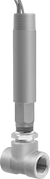
Safe to use where flammable gases and combustible dust may be present, these switches activate or deactivate when your flow reaches a factory-set level. All are UL listed for hazardous environments. Because their set point is fixed, they’re ready to go, making them easy to install. They actuate when your flowing liquid or gas pushes their paddle into a set position. These switches are single pole, double throw (SPDT) and can turn one device from off to on (normally open) or from on to off (normally closed). They must be mounted horizontally to function accurately.
These switches are calibrated with water and air. They can also be used with other liquids and gases but may not measure accurately if their viscosity is significantly different.
![]() For technical drawings and 3-D models, click on a part number.
For technical drawings and 3-D models, click on a part number.
Set Point | Conduit | |||||||||||||
|---|---|---|---|---|---|---|---|---|---|---|---|---|---|---|
| Pipe Size | Thread Type | Gender | For Liquids, gpm | For Gases, scfm | Max. Pressure | Temp. Range, °F | Voltage | Max. Switching Current | Trade Size | Thread Type | Gender | End-to-End Lg. | Each | |
Brass Body | ||||||||||||||
| 1/2 | NPT | Female | 1.5 | 6.5 | 250 psi @ 70° F | -4° to 220° | 120V AC/ 240V AC | 5 A @ 120 V AC | 3/4 | NPT | Male | 2 1/4" | 00000000 | 0000000 |
| 3/4 | NPT | Female | 2 | 10 | 250 psi @ 70° F | -4° to 220° | 120V AC/ 240V AC | 5 A @ 120 V AC | 3/4 | NPT | Male | 2 3/8" | 00000000 | 000000 |
| 1 | NPT | Female | 3 | 14 | 250 psi @ 70° F | -4° to 220° | 120V AC/ 240V AC | 5 A @ 120 V AC | 3/4 | NPT | Male | 2 1/2" | 00000000 | 000000 |
| 1 1/4 | NPT | Female | 4 | 21 | 250 psi @ 70° F | -4° to 220° | 120V AC/ 240V AC | 5 A @ 120 V AC | 3/4 | NPT | Male | 2 5/8" | 00000000 | 000000 |
| 1 1/2 | NPT | Female | 6 | 33 | 250 psi @ 70° F | -4° to 220° | 120V AC/ 240V AC | 5 A @ 120 V AC | 3/4 | NPT | Male | 2 7/8" | 00000000 | 000000 |
| 2 | NPT | Female | 10 | 43 | 250 psi @ 70° F | -4° to 220° | 120V AC/ 240V AC | 5 A @ 120 V AC | 3/4 | NPT | Male | 3" | 00000000 | 000000 |
304 Stainless Steel Body | ||||||||||||||
| 1/2 | NPT | Female | 1.5 | 6.5 | 2000 psi @ 70° F | -4° to 220° | 120V AC/ 240V AC | 5 A @ 120 V AC | 3/4 | NPT | Male | 2 1/4" | 00000000 | 000000 |
| 3/4 | NPT | Female | 2 | 10 | 2000 psi @ 70° F | -4° to 220° | 120V AC/ 240V AC | 5 A @ 120 V AC | 3/4 | NPT | Male | 2 5/8" | 00000000 | 000000 |
| 1 | NPT | Female | 3 | 14 | 2000 psi @ 70° F | -4° to 220° | 120V AC/ 240V AC | 5 A @ 120 V AC | 3/4 | NPT | Male | 3" | 00000000 | 000000 |
| 2 | NPT | Female | 10 | 43 | 2000 psi @ 70° F | -4° to 220° | 120V AC/ 240V AC | 5 A @ 120 V AC | 3/4 | NPT | Male | 4 3/4" | 00000000 | 00000000 |
Hazardous Location Flow Switches
UL listed for use where flammable gases or combustible dusts may be present, these flow switches activate or deactivate equipment when your flow rate reaches a set point. Use the adjustment screw to select their set point. They actuate when your flowing liquid or gas pushes their paddle into a certain position determined by the set point. All are single pole, double throw (SPDT) and can either turn one device from off to on (normally open) or on to off (normally closed). Mount them horizontally. Rated NEMA 4, they also protect against weather and washdowns.
These flow switches are calibrated with water and air. You can use them with other liquids and gases, but they may not measure accurately if the viscosity is different from water or air.
![]() For technical drawings and 3-D models, click on a part number.
For technical drawings and 3-D models, click on a part number.
Set Point | Conduit | |||||||||||||
|---|---|---|---|---|---|---|---|---|---|---|---|---|---|---|
| Pipe Size | Thread Type | Gender | For Liquids, gpm | For Gases, scfm | Max. Pressure | Temp. Range, °F | Voltage | Max. Switching Current | Trade Size | Thread Type | Gender | End-to-End Lg. | Each | |
Brass Body | ||||||||||||||
| 1/2 | NPT | Female | 0.04 to 0.75 | 0.18 to 2.7 | 1450 psi @ 70° F | -4° to 220° | 120V AC/ 240V AC | 5 A @ 120 V AC | 3/4 | NPT | Male | 3 5/8" | 00000000 | 0000000 |
304 Stainless Steel Body | ||||||||||||||
| 1/2 | NPT | Female | 0.04 to 0.75 | 0.18 to 2.7 | 1450 psi @ 70° F | -4° to 220° | 120V AC/ 240V AC | 5 A @ 120 V AC | 3/4 | NPT | Male | 3 5/8" | 00000000 | 000000 |
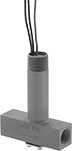
Hazardous Location Insertion Flow Switches
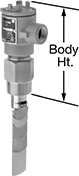
Safely activate and deactivate equipment in environments with flammable gases and combustible dust when your flow rate reaches a set point. They are UL listed and CSA certified for use in hazardous locations. These switches save you from disassembling your pipeline because you insert them into pipe tees or pipe outlets instead of mounting them inline. They actuate when your system’s liquid pushes the paddle into a set position. To change your set point, the paddle has multiple layers that you can remove. For the lowest set point, use the largest paddle that will fit your pipe. To increase your set point, loosen the locking washers and remove paddles. You can trim the paddles to fine-tune your set point. The smaller the paddle, the higher the setpoint.
They should be mounted vertically into a horizontal pipeline, so liquid pushes the paddle.
These switches are calibrated with water and air. They can also be used with other liquids and gases but may not measure accurately if their viscosity is significantly different.
SPDT (singe pole, double throw) switches can turn one device from off to on (normally open) or from on to off (normally closed).
DPDT (double pole, double throw) switches can either turn two devices from off to on (normally open) or on to off (normally closed).
![]() For technical drawings and 3-D models, click on a part number.
For technical drawings and 3-D models, click on a part number.
Set Point Range | Max. Flow Rate | Conduit | ||||||||||||||
|---|---|---|---|---|---|---|---|---|---|---|---|---|---|---|---|---|
| Pipe Size | Thread Type | Gender | For Pipe Size | For Water and Oil, gpm | For Air and Inert Gas, scfm | For Water and Oil, gpm | For Air and Inert Gas | Max. Pressure | Temp. Range, °F | Max. Switching Current @ Voltage | Trade Size | Thread Type | Gender | Body Ht. | Each | |
SPDT | ||||||||||||||||
Brass Body | ||||||||||||||||
| 1 1/2 | NPT | Male | 1 1/2 2 4 12 20 | 3 to 7 4 to 15 12 to 95 140 to 900 400 to 2,400 | 17 to 32 13 to 65 50 to 400 800 to 3,450 2,850 to 10,000 | 55 97 391 3,525 9,792 | Not Rated | 1000 psi @ 70° F | -4° to 275° | 5 A @ 125 V AC 5 A @ 250 V AC | 3/4 | NPT | Female | 8" | 00000000 | 0000000 |
316 Stainless Steel Body | ||||||||||||||||
| 1 1/2 | NPT | Male | 1 1/2 2 4 12 20 | 3 to 7 4 to 15 12 to 95 140 to 900 400 to 2,400 | 17 to 32 13 to 65 50 to 400 800 to 3,450 2,850 to 10,000 | 55 97 391 3,525 9,792 | Not Rated | 2000 psi @ 70° F | -4° to 275° | 5 A @ 125 V AC 5 A @ 250 V AC | 3/4 | NPT | Female | 8" | 00000000 | 00000000 |
DPDT | ||||||||||||||||
Brass Body | ||||||||||||||||
| 1 1/2 | NPT | Male | 1 1/2 2 4 12 20 | 3 to 7 4 to 15 12 to 95 140 to 900 400 to 2,400 | 17 to 32 13 to 65 50 to 400 800 to 3,450 2,850 to 10,000 | 55 97 391 3,525 9,792 | Not Rated | 1000 psi @ 70° F | -4° to 275° | 5 A @ 125 V AC 5 A @ 250 V AC | 3/4 | NPT | Female | 8" | 00000000 | 000000 |
316 Stainless Steel Body | ||||||||||||||||
| 1 1/2 | NPT | Male | 1 1/2 2 4 12 20 | 3 to 7 4 to 15 12 to 95 140 to 900 400 to 2,400 | 17 to 32 13 to 65 50 to 400 800 to 3,450 2,850 to 10,000 | 55 97 391 3,525 9,792 | Not Rated | 2000 psi @ 70° F | -4° to 275° | 5 A @ 125 V AC 5 A @ 250 V AC | 3/4 | NPT | Female | 8" | 00000000 | 00000000 |