


Filter by
For Use With
System of Measurement
Maximum Pressure @ Temperature
Mounting Position
Indicator Material
Maximum Temperature
Thread Type
Direction of Flow
Window Material
DFARS Specialty Metals
Export Control Classification Number (ECCN)
Flow Sights with Barbed Fittings for Water, Oil, Air, and Inert Gas
 | 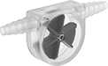 |
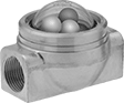
Ball Indicator | Rotor Indicator |
Monitor liquid movement, color, and clarity in tube systems—these sights have barbed fittings that slide into soft plastic and rubber tubing. They have a clear body and an indicator that moves when flow is present, so you can visually confirm flow from a distance.
Indicator | ||||||||||||
|---|---|---|---|---|---|---|---|---|---|---|---|---|
For Tube ID | Temp. Range, ° F | End-to-End Lg. | Ht. | Max. Pressure @ Temp. | Direction of Flow | Material | Color | For Use With | Each | |||
Ball Indicator | ||||||||||||
Polycarbonate Body | ||||||||||||
| 1/4" to 3/8" | 32 to 180 | 3" | 2 1/4" | 10 psi @ 70° F | Bottom to Top, Left to Right, Right to Left, Top to Bottom | Nylon | White | Water, Oil, Air, Inert Gas | 4218K61 | 000000 | ||
Rotor Indicator | ||||||||||||
PMP Body | ||||||||||||
| 1/4" to 7/16" | 32 to 140 | 3 1/2" | 1 9/16" | 20 psi @ 70° F | Bottom to Top, Left to Right, Right to Left, Top to Bottom | Polypropylene | Blue | Water, Mineral Oil, Air, Inert Gas | 4218K63 | 00000 | ||
Polystyrene Body | ||||||||||||
| 3/16" to 1/4" | 0 to 190 | 2" | 1" | 10 psi @ 70° F | Bottom to Top, Left to Right, Right to Left, Top to Bottom | Polystyrene | Blue | Water, Oil, Air, Inert Gas | 4218K62 | 00000 | ||
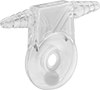
Panel-Mount Flow Sights for Water, Oil, and Inert Gas
 |
The included mounting ring lets you install these sights in instrument panels. They have three ball indicators that bounce in the domed-top window to show flow in your line.
Flow Sights | Repair Kits | ||||||||||||||||||
|---|---|---|---|---|---|---|---|---|---|---|---|---|---|---|---|---|---|---|---|
Window | Indicator | ||||||||||||||||||
Pipe Size | Thread Type | Gender | Temp. Range, ° F | Dia. | Type | End-to-End Lg. | Ht. | Max. Pressure @ Temp. | Panel Cutout Dia. | Direction of Flow | No. of | Material | For Use With | Each | Each | ||||
Ball Indicator | |||||||||||||||||||
Brass Body | |||||||||||||||||||
| 1/4 | NPT | Female | 35 to 120 | 1 5/8" | Domed Top | 3 1/8" | 2 1/8" | 150 psi @ 70° F | 2 3/8" | Bottom to Top, Left to Right, Right to Left, Top to Bottom | 3 | White Polyethylene White Polyethylene Green Acrylic Plastic | Water, Oil, Inert Gas | 4202K12 | 0000000 | 4202K216 | 000000 | ||
| 3/8 | NPT | Female | 35 to 120 | 1 5/8" | Domed Top | 3 1/8" | 2 1/8" | 150 psi @ 70° F | 2 3/8" | Bottom to Top, Left to Right, Right to Left, Top to Bottom | 3 | White Polyethylene White Polyethylene Green Acrylic Plastic | Water, Oil, Inert Gas | 4202K14 | 000000 | 4202K216 | 00000 | ||
| 1/2 | NPT | Female | 35 to 120 | 1 5/8" | Domed Top | 3 1/8" | 2 1/8" | 150 psi @ 70° F | 2 3/8" | Bottom to Top, Left to Right, Right to Left, Top to Bottom | 3 | White Polyethylene White Polyethylene Green Acrylic Plastic | Water, Oil, Inert Gas | 4202K16 | 000000 | 4202K216 | 00000 | ||
| 3/4 | NPT | Female | 35 to 120 | 1 5/8" | Domed Top | 3 1/8" | 2 1/8" | 150 psi @ 70° F | 2 3/8" | Bottom to Top, Left to Right, Right to Left, Top to Bottom | 3 | White Polyethylene White Polyethylene Green Acrylic Plastic | Water, Oil, Inert Gas | 4202K18 | 000000 | 4202K552 | 00000 | ||
| 1 | NPT | Female | 35 to 120 | 1 5/8" | Domed Top | 3 1/8" | 2 5/8" | 150 psi @ 70° F | 2 3/8" | Bottom to Top, Left to Right, Right to Left, Top to Bottom | 3 | White Polyethylene White Polyethylene Green Acrylic Plastic | Water, Oil, Inert Gas | 4202K19 | 000000 | 4202K552 | 00000 | ||
