


Matching Flow Diagrams to Replace an Air Directional Control Valve
More
Choosing an Air Directional Control Valve
More
Two-Action Air Directional Control Valves
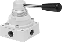
Also known as 4-way and 4/2 valves, these valves create two actions, such as extending and then retracting a double-acting cylinder. They direct airflow from the inlet to your equipment and exhaust return airflow to create motion. Valves without an exhaust connection exhaust air to the atmosphere.
Valves with hand return actuation stay actuated and return to their original position only when you move the actuator again.
Flow coefficient (Cv) is a measurement that indicates how much airflow can pass through a valve.
Overall | For Panel Cutout | |||||||||||||||
|---|---|---|---|---|---|---|---|---|---|---|---|---|---|---|---|---|
| No. of Flow Ports | Inlet Size | Outlet Size | Exhaust Connection Type | Max. Flow Rate, scfm @ 100 psi | Flow Coefficient (Cv) | Pressure Range, psi | Vacuum Rating | Lg. | Wd. | Ht. | Dia. | Dia. | Mounting Fasteners Included | Each | ||
Threaded Female Inlet × Threaded Female Outlet | ||||||||||||||||
Hand Return Actuation | ||||||||||||||||
| A | 4 | 1/8 NPT | 1/8 NPT | __ | 7.9 | 0.14 | 0-150 | Not Rated | __ | __ | 1 5/8" | 2" | __ | No | 6650K8 | 0000000 |
| B | 4 | 1/4 NPT | 1/4 NPT | Threaded | 14.13 | 0.4 | 0-140 | Not Rated | 5 1/4" | 2 1/2" | 3 1/2" | __ | 1 3/8" | No | 6650K11 | 00000 |
| B | 4 | 3/8 NPT | 3/8 NPT | Threaded | 38.85 | 1.1 | 0-140 | Not Rated | 5 7/8" | 2 7/8" | 4 1/8" | __ | 1 5/8" | No | 6650K12 | 000000 |
| B | 4 | 1/2 NPT | 1/2 NPT | Threaded | 109.48 | 3.1 | 0-140 | Not Rated | 6 3/8" | 4" | 4 7/8" | __ | 2" | No | 6650K13 | 000000 |
Two-Hand Two-Action Air Directional Control Valves
Since both hands are required to simultaneously press the buttons, these valves protect workers from accidental machinery start-up. Also known as 4-way and 4/2 valves, they create two actions, such as extending and then retracting a double-acting cylinder. They direct airflow from the inlet to your equipment and exhaust return airflow to create motion. Return actuation is by spring, so valves return to their original position as soon as you release the actuator.
Flow coefficient (Cv) is a measurement that indicates how much airflow can pass through a valve.
Overall | ||||||||||||||||
|---|---|---|---|---|---|---|---|---|---|---|---|---|---|---|---|---|
| Actuation Force, oz. | No. of Flow Ports | Inlet Size | For Inlet Tube OD | Outlet Size | For Outlet Tube OD | Exhaust Connection Type | Max. Flow Rate, scfm @ 100 psi | Flow Coefficient (Cv) | Pressure Range, psi | Vacuum Rating | Lg. | Wd. | Ht. | Mounting Fasteners Included | Each | |
Threaded Female Inlet × Threaded Female Outlet | ||||||||||||||||
| 6 | 4 | 1/4 NPTF | 1/4" | 1/4 NPTF | 1/4" | Threaded | 56 | 1 | 70-100 | Not Rated | 10 1/2" | 3 1/2" | 3 3/16" | No | 62115K24 | 000000000 |
| 18 | 4 | 1/4 NPTF | 1/4" | 1/4 NPTF | 1/4" | Threaded | 56 | 1 | 70-100 | Not Rated | 10 1/2" | 3 1/2" | 3 3/16" | No | 62115K23 | 00000000 |
Two-Action Air Directional Control Valves with Full Shut-Off
These valves close all ports in the off position to stop equipment in a locked position with air pressure holding it in place. Also known as 4-way and 4/3 closed-center valves, they create two actions, such as extracting and then retracting a double-acting cylinder. They direct airflow from the inlet to your equipment and exhaust return airflow to create motion. Return actuation is by hand, so valves stay actuated and return to their original position only when you move the actuator again.
Flow coefficient (Cv) is a measurement that indicates how much airflow can pass through a valve.
Overall | |||||||||||||
|---|---|---|---|---|---|---|---|---|---|---|---|---|---|
| No. of Flow Ports | Inlet Size | Outlet Size | Exhaust Connection Type | Max. Flow Rate, scfm @ 100 psi | Flow Coefficient (Cv) | Pressure Range, psi | Vacuum Rating | Lg. | Wd. | Ht. | Mounting Fasteners Included | Each | |
Threaded Female Inlet × Threaded Female Outlet | |||||||||||||
| 4 | 1/4 NPT | 1/4 NPT | Threaded | 125 | 3.4 | 0-145 | Not Rated | 5 5/8" | 4" | 4 3/4" | No | 62365K61 | 000000 |
| 4 | 3/8 NPT | 3/8 NPT | Threaded | 70 | 3 | 0-150 | Not Rated | 6 7/8" | 4 3/4" | 3 3/4" | No | 62365K63 | 000000 |
| 4 | 3/8 NPT | 3/8 NPT | Threaded | 70 | 3 | 0-250 | Not Rated | 6 7/8" | 4 3/4" | 3 3/4" | No | 62365K122 | 000000 |
| 4 | 1/2 NPT | 1/2 NPT | Threaded | 145 | 6.2 | 0-150 | Not Rated | 9" | 5 5/8" | 4 1/2" | No | 62365K65 | 000000 |
| 4 | 1/2 NPT | 1/2 NPT | Threaded | 145 | 6.2 | 0-250 | Not Rated | 9" | 5 5/8" | 4 1/2" | No | 62365K132 | 000000 |
Two-Action Air Directional Control Valves with Exhausting Shut-Off
In the off position, these valves exhaust all air pressure, allowing equipment to return to the neutral position. Also known as 4-way and 4/3 exhaust-center valves, they create two actions, such as extracting and then retracting a double-acting cylinder. They direct airflow from the inlet to your equipment and exhaust return airflow to create motion. Return actuation is by hand, so valves stay actuated and return to their original position only when you move the actuator again.
Flow coefficient (Cv) is a measurement that indicates how much airflow can pass through a valve.
Overall | |||||||||||||
|---|---|---|---|---|---|---|---|---|---|---|---|---|---|
| No. of Flow Ports | Inlet Size | Outlet Size | Exhaust Connection Type | Max. Flow Rate, scfm @ 100 psi | Flow Coefficient (Cv) | Pressure Range, psi | Vacuum Rating | Lg. | Wd. | Ht. | Mounting Fasteners Included | Each | |
Threaded Female Inlet × Threaded Female Outlet | |||||||||||||
| 4 | 1/4 NPT | 1/4 NPT | Threaded | 125 | 3.4 | 0-145 | Not Rated | 5 5/8" | 4" | 4 3/4" | No | 62365K62 | 000000 |
| 4 | 3/8 NPT | 3/8 NPT | Threaded | 70 | 3 | 0-150 | Not Rated | 6 7/8" | 4 3/4" | 3 3/4" | No | 62365K64 | 000000 |
| 4 | 1/2 NPT | 1/2 NPT | Threaded | 145 | 6.2 | 0-150 | Not Rated | 9" | 5 5/8" | 4 1/2" | No | 62365K66 | 000000 |
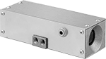
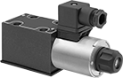
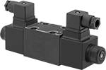
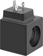
Two-Action Electrically Operated Air Directional Control Valves
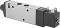
Also known as 4-way and 5/2 valves, these valves create two actions, such as extending and then retracting a double-acting cylinder. Apply voltage to the electrical connection to actuate. They direct airflow from the inlet to your equipment and exhaust return airflow to create motion. Return actuation is by spring, so they return to their original position as soon as voltage is removed.
Flow coefficient (Cv) is a measurement that indicates how much airflow can pass through a valve.
O'all | ||||||||||||||
|---|---|---|---|---|---|---|---|---|---|---|---|---|---|---|
| No. of Flow Ports | Inlet Size | Outlet Size | Max. Flow Rate, scfm @ 100 psi | Flow Coefficient (Cv) | Pressure Range, psi | Vacuum Rating | Lg. | Wd. | Ht. | Mount Type | Mounting Fasteners Included | Choose a Voltage | Each | |
Threaded Female Inlet × Threaded Female Outlet—Push-to-Connect Exhaust | ||||||||||||||
| 4 | 1/4 NPT | 1/4 NPT | 45 | 0.75 | 44-145 | Not Rated | 5 1/16" | 7/8" | 1 3/8" | Screw In, Inline | No | 62095K8 | 0000000 | |
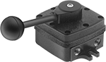
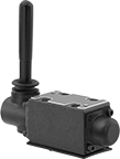
Two-Action Foot-Operated Air Directional Control Valves
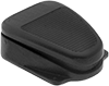
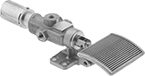
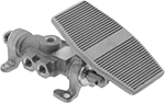
Also known as 4-way and 4/2 valves, these valves create two actions, such as extending and then retracting a cylinder. Use your foot to operate them, leaving your hands free to perform other tasks. Valves direct airflow from the inlet to your equipment and exhaust return airflow to create motion. Valves without an exhaust connection exhaust air to the atmosphere.
Valves with spring return actuation return to their original position as soon you release the actuator.
Valves with a foot return actuation stay actuated and return to their original position only when you step on them again.
Optional safety guards prevent accidental valve actuation.
Flow coefficient (Cv) is a measurement that indicates how much airflow can pass through a valve.
Valves | ||||||||||||||||||
|---|---|---|---|---|---|---|---|---|---|---|---|---|---|---|---|---|---|---|
O'all | Optional Safety Guards | Replacement Seal Kits | ||||||||||||||||
| No. of Flow Ports | Inlet Size | Outlet Size | Exhaust Connection Type | Max. Flow Rate, scfm @ 100 psi | Flow Coefficient (Cv) | Pressure Range, psi | Vacuum Rating, in. of Hg | Lg. | Wd. | Ht. | Mounting Fasteners Included | Each | Each | Each | ||||
Threaded Female Inlet × Threaded Female Outlet | ||||||||||||||||||
Spring Return Actuation | ||||||||||||||||||
| A | 4 | 1/8 NPT | 1/8 NPT | __ | 30 | 0.53 | 60-150 | Not Rated | 4 1/2" | 3 1/2" | 1 3/4" | No | 9781K31 | 0000000 | 7024K5 | 000000 | ______ | 00 |
| B | 4 | 1/4 NPTF | 1/4 NPTF | Threaded | 83 | 2.4 | 0-225 | 29 | 11 1/2" | 3 1/2" | 2 3/4" | No | 6654K11 | 000000 | ______ | 00 | 6654K111 | 000000 |
| B | 4 | 3/8 NPTF | 3/8 NPTF | Threaded | 118 | 3.2 | 0-225 | 29 | 12 1/2" | 3 1/2" | 2 3/4" | No | 6654K12 | 000000 | ______ | 00 | 6654K121 | 00000 |
| B | 4 | 1/2 NPTF | 1/2 NPTF | Threaded | 185 | 5.2 | 0-215 | 29 | 14 1/2" | 3 1/2" | 3 3/8" | No | 6654K13 | 000000 | ______ | 00 | ______ | 00 |
Foot Return Actuation | ||||||||||||||||||
| C | 4 | 1/4 NPTF | 1/4 NPTF | Threaded | 83 | 2.4 | 0-225 | 29 | 9 1/2" | 3 1/4" | 4 1/2" | No | 6654K21 | 000000 | ______ | 00 | 6654K211 | 00000 |
| C | 4 | 1/2 NPTF | 1/2 NPTF | Threaded | 185 | 5.2 | 0-215 | 29 | 12 1/8" | 3 1/4" | 4 7/8" | No | 6654K23 | 000000 | ______ | 00 | 6654K131 | 00000 |
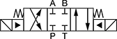
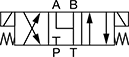
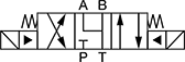
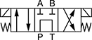
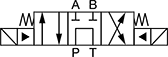
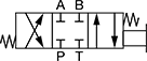
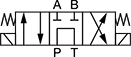
Solenoid-Operated Directional-Control Block-Mount Hydraulic Valves
Direct flow with an electronic signal. Use screws to attach to an NFPA valve-mounting block (each component sold separately).
In NFPA diagrams, P represents the pressure source, T represents the tank, and A and B represent work ports.


Valves | Screws | |||||||||
|---|---|---|---|---|---|---|---|---|---|---|
| NFPA Mounting Pattern | ISO Trade Size | Max. Flow Rate, gpm | Max. Pressure, psi | Choose a Voltage | Each | Pkg. Qty. | Pkg. | |||
Default Position: P Open to A, B Open to T | ||||||||||
| 1 | D03 | 3 | 20 | 5,000 | 49995K49 | 0000000 | 4 | 1945N12 | 00000 | |
| 1 | D05 | 5 | 40 | 5,000 | 49995K59 | 000000 | 4 | 1945N15 | 0000 | |
Default Position: P Open to B, A Open to T | ||||||||||
| 2 | D03 | 3 | 20 | 5,000 | 49995K58 | 000000 | 4 | 1945N12 | 0000 | |
| 2 | D05 | 5 | 40 | 5,000 | 49995K67 | 000000 | 4 | 1945N15 | 0000 | |
Valves | Screws | |||||||||
|---|---|---|---|---|---|---|---|---|---|---|
| NFPA Mounting Pattern | ISO Trade Size | Max. Flow Rate, gpm | Max. Pressure, psi | Choose a Voltage | Each | Pkg. Qty. | Pkg. | |||
Default Position: Closed | ||||||||||
| 3 | D03 | 3 | 20 | 5,000 | 49995K5 | 0000000 | 4 | 1945N12 | 00000 | |
| 3 | D05 | 5 | 40 | 5,000 | 49995K9 | 000000 | 4 | 1945N15 | 0000 | |
| 4 | D08 | 8 | 160 | 5,000 | 49995K27 | 00000000 | 6 | 1945N18 | 00000 | |
Default Position: Open | ||||||||||
| 5 | D03 | 3 | 20 | 5,000 | 49995K6 | 000000 | 4 | 1945N12 | 0000 | |
| 5 | D05 | 5 | 40 | 5,000 | 49995K17 | 000000 | 4 | 1945N15 | 0000 | |
| 6 | D08 | 8 | 160 | 5,000 | 49995K29 | 00000000 | 6 | 1945N18 | 00000 | |
Default Position: P Closed, A and B Open to T | ||||||||||
| 7 | D03 | 3 | 10 | 5,000 | 49995K7 | 000000 | 4 | 1945N12 | 0000 | |
| 7 | D05 | 5 | 40 | 5,000 | 49995K18 | 000000 | 4 | 1945N15 | 0000 | |
| 8 | D08 | 8 | 160 | 5,000 | 49995K47 | 00000000 | 6 | 1945N18 | 00000 | |
Default Position: P Open to T, A and B Closed | ||||||||||
| 9 | D03 | 3 | 15 | 5,000 | 49995K8 | 000000 | 4 | 1945N12 | 0000 | |
| 9 | D05 | 5 | 10 | 5,000 | 49995K19 | 000000 | 4 | 1945N15 | 0000 | |
| 10 | D08 | 8 | 80 | 5,000 | 49995K48 | 00000000 | 6 | 1945N18 | 00000 | |
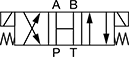
Toggle-Operated Directional-Control Block-Mount Hydraulic Valves
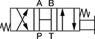
Direct flow manually with a lever. A spring returns the valve to its default position once the lever is released. Often used before a double-acting cylinder. Use screws to attach to an NFPA valve-mounting block (each component sold separately).
In NFPA diagrams, P represents the pressure source, T represents the tank, and A and B represent work ports.
Valves | ||||||||||||
|---|---|---|---|---|---|---|---|---|---|---|---|---|
O'all | Screws | |||||||||||
| NFPA Mounting Pattern | ISO Trade Size | Max. Flow Rate, gpm | Max. Pressure, psi | Lg. | Wd. | Ht. | Each | Pkg. Qty. | Pkg. | |||
Four-Way Valves—3 Flow Positions (4/3 Valves) | ||||||||||||
Default Position: Closed | ||||||||||||
| 1 | D03 | 3 | 22 | 5,000 | 5 7/8" | 1 7/8" | 6" | 4393T411 | 0000000 | 4 | 1945N12 | 00000 |
| 1 | D05 | 5 | 40 | 5,000 | 6 7/8" | 2 3/4" | 6 3/8" | 4393T415 | 00000000 | 4 | 1945N15 | 0000 |
Default Position: Open | ||||||||||||
| 2 | D03 | 3 | 22 | 5,000 | 5 7/8" | 1 7/8" | 6" | 4393T412 | 000000 | 4 | 1945N12 | 0000 |
Default Position: P Closed, A and B Open to T | ||||||||||||
| 3 | D03 | 3 | 12 | 5,000 | 5 7/8" | 1 7/8" | 6" | 4393T413 | 000000 | 4 | 1945N12 | 0000 |
| 3 | D05 | 5 | 40 | 5,000 | 6 7/8" | 2 3/4" | 6 3/8" | 4393T417 | 00000000 | 4 | 1945N15 | 0000 |
Default Position: P Open to T, A and B Closed | ||||||||||||
| 4 | D03 | 3 | 12 | 5,000 | 5 7/8" | 1 7/8" | 6" | 4393T414 | 000000 | 4 | 1945N12 | 0000 |
| 4 | D05 | 5 | 13 | 5,000 | 6 7/8" | 2 3/4" | 6 3/8" | 4393T418 | 00000000 | 4 | 1945N15 | 0000 |
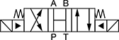
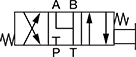
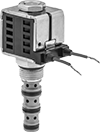
Directional-Control Screw-In Hydraulic Valves
Control the direction of flow or stop flow altogether with an electronic signal. These valves are also known as cartridge valves, and they screw into your mounting block.
Place four-way valves between the pressure source and a double-acting cylinder.
In NFPA diagrams, P represents the pressure source, T represents the tank, and A and B represent work ports.


Valves | ||||||||||||
|---|---|---|---|---|---|---|---|---|---|---|---|---|
Body—UN/UNF (SAE Straight) | Replacement Solenoid Coils | |||||||||||
| Deltrol Equivalent Model No. | Hydraforce Equivalent Model No. | Parker Equivalent Model No. | Thread Size | Dash Size | Max. Flow Rate, gpm | Max. Pressure, psi | Voltage | O'all Ht. | Each | Each | ||
Style 2—Default Position: Closed | ||||||||||||
| DSV2-080-4NC-N-D2DE | SV08-41-0-N-24EL | DSL084-N-N-DP-D024-L | 3/4"-16 | 08 | 3 | 3,000 | 24V DC | 4 1/16" | 1643N46 | 000000 | 1678N12 | 000000 |
Style 3—Default Position: P Open to A, B Open to T | ||||||||||||
| DSV2-100-4CO-N-D1D | SV10-40-0-N-12DL | DSL104-B-N-D012-L | 7/8"-14 | 10 | 6 | 3,000 | 12V DC | 4 7/8" | 1643N43 | 000000 | 1678N13 | 00000 |
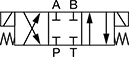
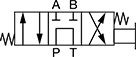
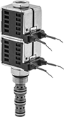 Double-Solenoid Four-Way Valve | 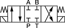 4 |
 5 |
Valves | |||||||||||
|---|---|---|---|---|---|---|---|---|---|---|---|
Body—UN/UNF (SAE Straight) | Replacement Solenoid Coils | ||||||||||
| Deltrol Equivalent Model No. | Hydraforce Equivalent Model No. | Thread Size | Dash Size | Max. Flow Rate, gpm | Max. Pressure, psi | Voltage | O'all Ht. | Each | Each | ||
Style 4—Default Position: Closed | |||||||||||
| DSV-080-34C-N-D1DE | SV08-47C-0-N-12EL | 3/4"-16 | 08 | 3 | 3,000 | 12V DC | 5 1/2" | 1643N62 | 0000000 | 1678N11 | 000000 |
Style 5—Default Position: P Open to T, A and B Closed | |||||||||||
| DSV-080-34T-N-D1DE | SV08-47A-0-N-12EL | 3/4"-16 | 08 | 3 | 3,000 | 12V DC | 5 1/2" | 1643N78 | 000000 | 1678N11 | 00000 |
| DSV-080-34T-N-D2DE | SV08-47A-0-N-24EL | 3/4"-16 | 08 | 3 | 3,000 | 24V DC | 5 1/2" | 1643N79 | 000000 | 1678N12 | 00000 |