


Filter by
Measurement Unit
Magnetic Field Measuring
Measures
Magnetic Field Measuring Range
Frequency Bandwidth
Pole Indicating Color
DFARS Specialty Metals
Alert Type
Electric Field Measuring
Sensor Type
Input Voltage
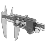
Digital Magnetic Field Indicators
 |
Measure magnetic fields to determine electromagnetic interference and detect flaws in welded metal.
Cannot Be Sold To—Product regulations restrict sales to the listed jurisdictions/areas.
Measurement Unit | Measuring Range (Increments) | Accuracy | Freq. Bandwith, kHz | Batteries Included | Includes | Cannot Be Sold To | Each | ||
|---|---|---|---|---|---|---|---|---|---|
| Amperes per Meter, Gauss, Teslas | 0 G to 100 G (0.01 G) 0 kG to 1 kG (0.1 G) 0 kG to 10 kG (1 G) 0 kG to 45 kG (10 G) | ±2% | 0 to 5 | Yes | AC Adapter, Detachable Probe | California | 1488T56 | 000000000 |
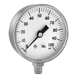
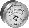
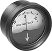
Calibrated-Dial Magnetic Field Indicators
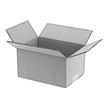
 | 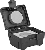 |
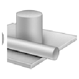
Protective Case |
Indicators | Protective Cases | |||||||
|---|---|---|---|---|---|---|---|---|
Dial | ||||||||
Magnetic Field Measuring Range | Dia. | Face Color | Housing Material | Each | Each | |||
| 5-0-5 Gauss | 2 1/2" | White | Aluminum | 8450T31 | 0000000 | 8450T32 | 000000 | |
| 10-0-10 Gauss | 2 1/2" | White | Aluminum | 8450T14 | 000000 | 8450T32 | 00000 | |
| 20-0-20 Gauss | 2 1/2" | White | Aluminum | 8450T16 | 000000 | 8450T32 | 00000 | |
| 50-0-50 Gauss | 2 1/2" | White | Aluminum | 8450T18 | 000000 | 8450T32 | 00000 | |
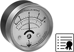
Calibrated-Dial Magnetic Field Indicators with Certificate of Calibration
Digital Electromagnetic Field Indicators
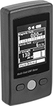 |
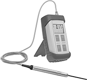
Measure the strength of magnetic fields, electric fields, and radio frequencies at the same time. To detect emissions, just point these meters at the electrical equipment you want to test, such as a cable. When they detect high levels that could damage sensitive equipment, an alert appears in red and an audible alarm sounds. Their color LCD display shows readings, bar graphs, and trending graphs.
These indicators store up to 20 radio frequency readings. Send readings to your PC using a USB cable (not included).
Measurement Unit | Measures | Measuring Range (Increments) | Accuracy | Frequency Bandwith | Ht. | Wd. | Dp. | Batteries Included | Each | ||
|---|---|---|---|---|---|---|---|---|---|---|---|
| Gauss, Teslas | Magnetic Field Strength Electric Field Strength Radio Frequency Strength Magnetic Field Direction (3-Axis) | 0.02 G to 2 G (0.01 G) 50 V/m to 2,000 V/m (1 V/m) 0.03 V/m to 14.46 V/m (0.02 V/m) | ±15% ±7% ±2 dB | 0.05 kHz to 0.06 kHz 0.05 kHz to 0.06 kHz 50,000 kHz to 3,500,000 kHz | 4 1/2" | 2 1/2" | 1" | Yes | 7401N11 | 0000000 |
Dial Magnetic Field Indicators
 |
Dial | ||||||
|---|---|---|---|---|---|---|
Magnetic Field Measuring Range | Dia. | Face Color | Housing Material | Each | ||
| 10-0-10 Gauss | 2" | White | Plastic | 8575T11 | 0000000 | |
Electronic Polarity Testers
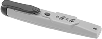 |
Lg. | Wd. | Batteries Included | Each | ||
|---|---|---|---|---|---|
| 5 1/2" | 1" | Yes | 57255K71 | 000000 |
Magnetic Field Detectors
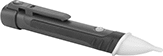 |
Troubleshoot solenoid valves, check relays, and test permanent magnets by detecting if a magnetic field is present. Hold these detectors near a surface and they'll light up blue if they sense a magnetic field. They don't measure the strength or direction of the magnetic field.
Detects | Lg. | Wd. | Batteries Included | Features | Each | ||
|---|---|---|---|---|---|---|---|
| Magnetic Fields | 6 1/4" | 1" | Yes | Flashlight, Low Battery Indicator | 7246N11 | 000000 |
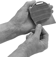
Paper Magnetic Polarity Testers
Motion-Measuring Modules for Development Boards
Modules with Magnetometer
 |
A magnetometer measures your device's orientation.
Output Data | |||||||||||||||||||||||||||||||||||||||||||||||||||||||||||||||||||||||||||||||||||||||||||||||||||
|---|---|---|---|---|---|---|---|---|---|---|---|---|---|---|---|---|---|---|---|---|---|---|---|---|---|---|---|---|---|---|---|---|---|---|---|---|---|---|---|---|---|---|---|---|---|---|---|---|---|---|---|---|---|---|---|---|---|---|---|---|---|---|---|---|---|---|---|---|---|---|---|---|---|---|---|---|---|---|---|---|---|---|---|---|---|---|---|---|---|---|---|---|---|---|---|---|---|---|---|
Magnetic Field Measuring, G | Resolution, bit | Freq., kHz | Measures | Temp. Range, ° F | Input Voltage, V DC | I2C Address | Connection Method | No. of Qwiic Connections | Lg. | Wd. | Each | ||||||||||||||||||||||||||||||||||||||||||||||||||||||||||||||||||||||||||||||||||||||||
I²C Communication Protocol—Qwiic Connection | |||||||||||||||||||||||||||||||||||||||||||||||||||||||||||||||||||||||||||||||||||||||||||||||||||
| 0 to 8 | 18 | 1 | Magnetic Field Strength | -40 to 220 | 2.8 to 3.6 | 0x30 | Solder | 1 | 3/4" | 5/16" | 8184N14 | 000000 | |||||||||||||||||||||||||||||||||||||||||||||||||||||||||||||||||||||||||||||||||||||||
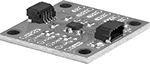
Modules with Accelerometer, Gyroscope, Magnetometer
|
A gyroscope measures how fast your device is rotating.
A magnetometer measures your device's orientation.
An accelerometer measures the rate at which your device is speeding up or slowing down.
Output Data | |||||||||||||||||||||||||||||||||||||||||||||||||||||||||||||||||||||||||||||||||||||||||||||||||||
|---|---|---|---|---|---|---|---|---|---|---|---|---|---|---|---|---|---|---|---|---|---|---|---|---|---|---|---|---|---|---|---|---|---|---|---|---|---|---|---|---|---|---|---|---|---|---|---|---|---|---|---|---|---|---|---|---|---|---|---|---|---|---|---|---|---|---|---|---|---|---|---|---|---|---|---|---|---|---|---|---|---|---|---|---|---|---|---|---|---|---|---|---|---|---|---|---|---|---|---|
Accel., g | Velocity | Magnetic Field Measuring, G | Resolution, bit | Freq., kHz | Measures | Temp. Range, ° F | Input Voltage, V DC | I2C Address | Connection Method | No. of Qwiic Connections | Lg. | Wd. | Each | ||||||||||||||||||||||||||||||||||||||||||||||||||||||||||||||||||||||||||||||||||||||
I²C Communication Protocol—Qwiic Connection | |||||||||||||||||||||||||||||||||||||||||||||||||||||||||||||||||||||||||||||||||||||||||||||||||||
| 2 4 8 16 | 125 °/s 250 °/s 500 °/s 1,000 °/s 2,000 °/s 4,000 °/s | 0 to 8 | 18 | 1 | Acceleration, Angular Velocity, Magnetic Field Strength | -40 to 220 | 1.71 to 3.6 | 0x6A 0x6B 0x30 | Solder | 2 | 1" | 1" | 8184N13 | 000000 | |||||||||||||||||||||||||||||||||||||||||||||||||||||||||||||||||||||||||||||||||||||
