


Filter by


Shaft Orientation

Maximum Output Speed

Maximum Input Power
Number of Output Shafts


Maximum Output Torque @ Input Speed
Material
Component

Input Shaft Rotation


Gear Box Input Connection

Gear Box Output Connection

U.S.–Mexico–Canada Agreement (USMCA) Qualifying
Export Control Classification Number (ECCN)
DFARS Specialty Metals
Speed Reducers for Position- and Speed-Control Motors
With 1 Output Shaft
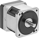 |
IP65 Enclosure Rating—They meet IP65 for protection from washdowns.
Radial Load Capacity—Radial loads are loads that are perpendicular to the shaft. They’re commonly caused by components attached to shaft, such as pulleys and sprockets.
Max. Output | Max. Input | Output Shaft | Overall | ||||||||||||||||||||||||||||||||||||||||||||||||||||||||||||||||||||||||||||||||||||||||||||||||
|---|---|---|---|---|---|---|---|---|---|---|---|---|---|---|---|---|---|---|---|---|---|---|---|---|---|---|---|---|---|---|---|---|---|---|---|---|---|---|---|---|---|---|---|---|---|---|---|---|---|---|---|---|---|---|---|---|---|---|---|---|---|---|---|---|---|---|---|---|---|---|---|---|---|---|---|---|---|---|---|---|---|---|---|---|---|---|---|---|---|---|---|---|---|---|---|---|---|---|---|
Torque | Speed, rpm | Speed, rpm | Power, hp | For Input Shaft Dia. | Dia. | Lg. | Lg. | Wd. | Ht. | Radial Load Cap., lb. | Enclosure Rating | Each | |||||||||||||||||||||||||||||||||||||||||||||||||||||||||||||||||||||||||||||||||||||||
For NEMA 23 Motor Frames | |||||||||||||||||||||||||||||||||||||||||||||||||||||||||||||||||||||||||||||||||||||||||||||||||||
3:1 Speed Ratio | |||||||||||||||||||||||||||||||||||||||||||||||||||||||||||||||||||||||||||||||||||||||||||||||||||
| 240 in·lbf @ 1,750 rpm | 2,000 | 6,000 | 2.89 | 1/4" | 0.38" | 1" | 4 1/2" | 2 1/2" | 2 1/2" | 348 | IP65 | 64815K41 | 000000000 | ||||||||||||||||||||||||||||||||||||||||||||||||||||||||||||||||||||||||||||||||||||||
5:1 Speed Ratio | |||||||||||||||||||||||||||||||||||||||||||||||||||||||||||||||||||||||||||||||||||||||||||||||||||
| 345 in·lbf @ 1,750 rpm | 1,200 | 6,000 | 3.24 | 1/4" | 0.38" | 1" | 4 1/2" | 2 1/2" | 2 1/2" | 348 | IP65 | 64815K42 | 00000000 | ||||||||||||||||||||||||||||||||||||||||||||||||||||||||||||||||||||||||||||||||||||||
10:1 Speed Ratio | |||||||||||||||||||||||||||||||||||||||||||||||||||||||||||||||||||||||||||||||||||||||||||||||||||
| 265 in·lbf @ 1,750 rpm | 600 | 6,000 | 1.45 | 1/4" | 0.38" | 1" | 4 1/2" | 2 1/2" | 2 1/2" | 348 | IP65 | 64815K43 | 00000000 | ||||||||||||||||||||||||||||||||||||||||||||||||||||||||||||||||||||||||||||||||||||||
20:1 Speed Ratio | |||||||||||||||||||||||||||||||||||||||||||||||||||||||||||||||||||||||||||||||||||||||||||||||||||
| 345 in·lbf @ 1,750 rpm | 300 | 6,000 | 1.08 | 1/4" | 0.38" | 1" | 5 3/4" | 2 1/2" | 2 1/2" | 348 | IP65 | 64815K44 | 00000000 | ||||||||||||||||||||||||||||||||||||||||||||||||||||||||||||||||||||||||||||||||||||||
50:1 Speed Ratio | |||||||||||||||||||||||||||||||||||||||||||||||||||||||||||||||||||||||||||||||||||||||||||||||||||
| 345 in·lbf @ 1,750 rpm | 120 | 6,000 | 0.46 | 1/4" | 0.38" | 1" | 5 3/4" | 2 1/2" | 2 1/2" | 348 | IP65 | 64815K45 | 00000000 | ||||||||||||||||||||||||||||||||||||||||||||||||||||||||||||||||||||||||||||||||||||||
For NEMA 34 Motor Frames | |||||||||||||||||||||||||||||||||||||||||||||||||||||||||||||||||||||||||||||||||||||||||||||||||||
3:1 Speed Ratio | |||||||||||||||||||||||||||||||||||||||||||||||||||||||||||||||||||||||||||||||||||||||||||||||||||
| 743 in·lbf @ 1,750 rpm | 1,833 | 5,500 | 6.75 | 1/2" | 1/2" | 1.25" | 5 1/4" | 3 1/2" | 3 1/2" | 630 | IP65 | 64815K51 | 00000000 | ||||||||||||||||||||||||||||||||||||||||||||||||||||||||||||||||||||||||||||||||||||||
5:1 Speed Ratio | |||||||||||||||||||||||||||||||||||||||||||||||||||||||||||||||||||||||||||||||||||||||||||||||||||
| 867 in·lbf @ 1,750 rpm | 1,100 | 5,500 | 5.73 | 1/2" | 1/2" | 1.25" | 5 1/4" | 3 1/2" | 3 1/2" | 630 | IP65 | 64815K52 | 00000000 | ||||||||||||||||||||||||||||||||||||||||||||||||||||||||||||||||||||||||||||||||||||||
10:1 Speed Ratio | |||||||||||||||||||||||||||||||||||||||||||||||||||||||||||||||||||||||||||||||||||||||||||||||||||
| 797 in·lbf @ 1,750 rpm | 550 | 5,500 | 3.04 | 1/2" | 1/2" | 1.25" | 5 1/4" | 3 1/2" | 3 1/2" | 630 | IP65 | 64815K53 | 00000000 | ||||||||||||||||||||||||||||||||||||||||||||||||||||||||||||||||||||||||||||||||||||||
20:1 Speed Ratio | |||||||||||||||||||||||||||||||||||||||||||||||||||||||||||||||||||||||||||||||||||||||||||||||||||
| 867 in·lbf @ 1,750 rpm | 275 | 5,500 | 1.97 | 1/2" | 1/2" | 1.25" | 7" | 3 1/2" | 3 1/2" | 630 | IP65 | 64815K54 | 00000000 | ||||||||||||||||||||||||||||||||||||||||||||||||||||||||||||||||||||||||||||||||||||||
50:1 Speed Ratio | |||||||||||||||||||||||||||||||||||||||||||||||||||||||||||||||||||||||||||||||||||||||||||||||||||
| 867 in·lbf @ 1,750 rpm | 110 | 5,500 | 0.87 | 1/2" | 1/2" | 1.25" | 7" | 3 1/2" | 3 1/2" | 630 | IP65 | 64815K55 | 00000000 | ||||||||||||||||||||||||||||||||||||||||||||||||||||||||||||||||||||||||||||||||||||||
High-Power Metal Helical Gears
Crossed Gears
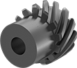 |
Crossed helical gears, also known as screw gears, can be configured to transmit motion at a 90° angle or in a straight line. To transmit motion at a 90° angle, pair two gears with the same tooth direction. To transmit motion in a straight line, make sure to get one left-hand and one right-hand gear.
For gears to mesh correctly, they must have the same pressure angle and pitch/module. To change speed and torque in your assembly, pair two gears with different numbers of teeth.
Hub | Keyway | Left-Hand Teeth | Right-Hand Teeth | ||||||||||||||||||||||||||||||||||||||||||||||||||||||||||||||||||||||||||||||||||||||||||||||||
|---|---|---|---|---|---|---|---|---|---|---|---|---|---|---|---|---|---|---|---|---|---|---|---|---|---|---|---|---|---|---|---|---|---|---|---|---|---|---|---|---|---|---|---|---|---|---|---|---|---|---|---|---|---|---|---|---|---|---|---|---|---|---|---|---|---|---|---|---|---|---|---|---|---|---|---|---|---|---|---|---|---|---|---|---|---|---|---|---|---|---|---|---|---|---|---|---|---|---|---|
Gear Pitch | Gear Module | No. of Teeth | Helix Angle | Gear Pitch Dia. | OD | Face Wd. | Dia. | Wd. | Bore Type | For Shaft Dia. | Wd. | Dp. | Material | Tooth Heat Treatment | Each | Each | |||||||||||||||||||||||||||||||||||||||||||||||||||||||||||||||||||||||||||||||||||
20° Pressure Angle | |||||||||||||||||||||||||||||||||||||||||||||||||||||||||||||||||||||||||||||||||||||||||||||||||||
| — | 1 | 13 | 45° | 18.4 mm | 20.38 mm | 10 mm | 15 mm | 10 mm | Round Bore | 6 mm | — | — | Black-Oxide 1045 Carbon Steel | Not Hardened | 3598N289 | 000000 | 3598N291 | 000000 | |||||||||||||||||||||||||||||||||||||||||||||||||||||||||||||||||||||||||||||||||
| — | 1 | 26 | 45° | 36.8 mm | 38.77 mm | 10 mm | 30 mm | 10 mm | Round Bore | 10 mm | — | — | Black-Oxide 1045 Carbon Steel | Not Hardened | 3598N296 | 00000 | 3598N297 | 00000 | |||||||||||||||||||||||||||||||||||||||||||||||||||||||||||||||||||||||||||||||||
| — | 1 | 30 | 45° | 42.4 mm | 44.43 mm | 10 mm | 35 mm | 10 mm | Round Bore | 10 mm | — | — | Black-Oxide 1045 Carbon Steel | Not Hardened | 3598N298 | 00000 | 3598N299 | 00000 | |||||||||||||||||||||||||||||||||||||||||||||||||||||||||||||||||||||||||||||||||
| — | 1.5 | 10 | 45° | 21.2 mm | 24.21 mm | 15 mm | 16 mm | 10 mm | Round Bore | 8 mm | — | — | Black-Oxide 1045 Carbon Steel | Not Hardened | 3598N276 | 00000 | 3598N277 | 00000 | |||||||||||||||||||||||||||||||||||||||||||||||||||||||||||||||||||||||||||||||||
| — | 1.5 | 13 | 45° | 27.6 mm | 30.58 mm | 15 mm | 23 mm | 10 mm | Round Bore | 10 mm | — | — | Black-Oxide 1045 Carbon Steel | Not Hardened | 3598N278 | 00000 | 3598N279 | 00000 | |||||||||||||||||||||||||||||||||||||||||||||||||||||||||||||||||||||||||||||||||
| — | 1.5 | 26 | 45° | 55.2 mm | 58.15 mm | 15 mm | 40 mm | 10 mm | Round Bore | 12 mm | — | — | Black-Oxide 1045 Carbon Steel | Not Hardened | 3598N285 | 00000 | 3598N286 | 00000 | |||||||||||||||||||||||||||||||||||||||||||||||||||||||||||||||||||||||||||||||||
14 1/2° Pressure Angle | |||||||||||||||||||||||||||||||||||||||||||||||||||||||||||||||||||||||||||||||||||||||||||||||||||
| 16 | — | 16 | 45° | 1" | 1.09" | 1/2" | 0.86" | 0.5" | Keyed Bore with Set Screw | 1/2" | 0.125" | 0.062" | 1137 Carbon Steel | Hardened | 2585N11 | 00000 | 2585N12 | 00000 | |||||||||||||||||||||||||||||||||||||||||||||||||||||||||||||||||||||||||||||||||
| 16 | — | 24 | 45° | 1 1/2" | 1.59" | 1/2" | 1.37" | 0.5" | Keyed Bore with Set Screw | 5/8" | 0.187" | 0.094" | 1137 Carbon Steel | Hardened | 2585N13 | 000000 | 2585N14 | 000000 | |||||||||||||||||||||||||||||||||||||||||||||||||||||||||||||||||||||||||||||||||
| 16 | — | 32 | 45° | 2" | 2.09" | 1/2" | 1.87" | 0.5" | Keyed Bore with Set Screw | 5/8" | 0.187" | 0.094" | 1137 Carbon Steel | Hardened | 2585N15 | 000000 | 2585N16 | 000000 | |||||||||||||||||||||||||||||||||||||||||||||||||||||||||||||||||||||||||||||||||
| 16 | — | 48 | 45° | 3" | 3.09" | 1/2" | 2.5" | 0.5" | Keyed Bore with Set Screw | 5/8" | 0.187" | 0.094" | 1137 Carbon Steel | Hardened | 2585N17 | 000000 | 2585N18 | 000000 | |||||||||||||||||||||||||||||||||||||||||||||||||||||||||||||||||||||||||||||||||
| 12 | — | 18 | 45° | 1 1/2" | 1.62" | 3/4" | 1.34" | 0.5" | Keyed Bore with Set Screw | 5/8" | 0.187" | 0.094" | 1137 Carbon Steel | Hardened | 2585N22 | 000000 | 2585N23 | 000000 | |||||||||||||||||||||||||||||||||||||||||||||||||||||||||||||||||||||||||||||||||
Parallel Gears
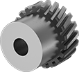 |
Pair two parallel gears to transmit motion in a straight line or a gear with a rack to convert rotary motion to linear motion. Make sure mating components have different tooth directions.
For gears to mesh correctly, they must have the same pressure angle and pitch/module. To change speed and torque in your assembly, pair two gears with different numbers of teeth.
Hub, mm | Left-Hand Teeth | Right-Hand Teeth | |||||||||||||||||||||||||||||||||||||||||||||||||||||||||||||||||||||||||||||||||||||||||||||||||
|---|---|---|---|---|---|---|---|---|---|---|---|---|---|---|---|---|---|---|---|---|---|---|---|---|---|---|---|---|---|---|---|---|---|---|---|---|---|---|---|---|---|---|---|---|---|---|---|---|---|---|---|---|---|---|---|---|---|---|---|---|---|---|---|---|---|---|---|---|---|---|---|---|---|---|---|---|---|---|---|---|---|---|---|---|---|---|---|---|---|---|---|---|---|---|---|---|---|---|---|
Gear Module | No. of Teeth | Helix Angle | Gear Pitch Dia., mm | OD, mm | Face Wd., mm | Dia. | Wd. | Bore Type | For Shaft Dia., mm | Material | Tooth Heat Treatment | Each | Each | ||||||||||||||||||||||||||||||||||||||||||||||||||||||||||||||||||||||||||||||||||||||
20° Pressure Angle | |||||||||||||||||||||||||||||||||||||||||||||||||||||||||||||||||||||||||||||||||||||||||||||||||||
| 1 | 20 | 21 1/2° | 20 | 22 | 8 | 17 | 10 | Round Bore | 6 | 4140 Alloy Steel | Hardened | 3598N159 | 000000 | 3598N161 | 000000 | ||||||||||||||||||||||||||||||||||||||||||||||||||||||||||||||||||||||||||||||||||||
| 1 | 30 | 21 1/2° | 30 | 32 | 8 | 25 | 10 | Round Bore | 10 | 4140 Alloy Steel | Hardened | 3598N171 | 000000 | 3598N172 | 000000 | ||||||||||||||||||||||||||||||||||||||||||||||||||||||||||||||||||||||||||||||||||||
| 1 | 44 | 21 1/2° | 44 | 46 | 8 | 30 | 10 | Round Bore | 10 | 4140 Alloy Steel | Hardened | 3598N182 | 000000 | 3598N183 | 000000 | ||||||||||||||||||||||||||||||||||||||||||||||||||||||||||||||||||||||||||||||||||||
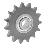
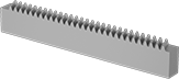
Parallel Gear Racks
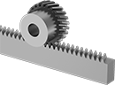 |  |
Parallel Gear on Gear Rack (Sold Separately) |
Pair these racks with parallel helical gears that have an opposite tooth direction to convert rotary motion to linear motion.
