How to Identify and Measure Fittings
Pipe size is an industry designation, not the actual size. View information about how to measure threaded and unthreaded pipe and pipe fittings.
More
High-Pressure Stainless Steel Unthreaded SAE Pipe Flanges
Create an access point in a high-pressure hydraulic fluid line with these flanges. They are also known as Code 61 SAE hydraulic flanges. To connect, bolt a flange with an O-ring groove surface to a flange with a flat surface of the same size. Flanges are 316 stainless steel for excellent corrosion resistance.
Socket-connect flanges weld to pipe for a strong, permanent connection. Cap flanges are also known as blind flanges.


- For Use With: Hydraulic Fluid
- Specifications Met: SAE J518, ISO 6162
Flange | Bolt Hole | 316/316L Stainless Steel | |||||||||||
|---|---|---|---|---|---|---|---|---|---|---|---|---|---|
| Pipe Size | SAE Flange Size | Dash Size | Max. Pressure | Ht. | Wd. | Dp. | Mounting Hardware Included | For Bolt Dia. | Dia. | No. of | Ctr.-to-Ctr. | Each | |
| 3/4 | 3/4 | 12 | 5,000 psi @ 72° F | 2 5/8" | 1 3/4" | 15/16" | Yes | 3/8" | 0.406" | 4 | 7/8", 1 7/8" | 00000000 | 0000000 |
| 1 | 1 | 16 | 5,000 psi @ 72° F | 2 53/64" | 2" | 15/16" | Yes | 3/8" | 0.406" | 4 | 1.031", 2.062" | 00000000 | 000000 |
| 1 1/2 | 1 1/2 | 24 | 3,000 psi @ 72° F | 3 3/4" | 2 3/4" | 1 3/16" | Yes | 1/2" | 0.531" | 4 | 1.406", 2 3/4" | 00000000 | 000000 |
| 2 | 2 | 32 | 3,000 psi @ 72° F | 4" | 3 1/4" | 1 7/16" | Yes | 1/2" | 0.531" | 4 | 1.688", 3.062" | 00000000 | 000000 |


- For Use With: Hydraulic Fluid
- Specifications Met: SAE J518, ISO 6162
Flange | Bolt Hole | 316/316L Stainless Steel | ||||||||||
|---|---|---|---|---|---|---|---|---|---|---|---|---|
| SAE Flange Size | Dash Size | Max. Pressure | Ht. | Wd. | Dp. | Mounting Hardware Included | For Bolt Dia. | Dia. | No. of | Ctr.-to-Ctr. | Each | |
| 2 | 32 | 3,000 psi @ 72° F | 4" | 3 1/4" | 1 45/64" | Yes | 1/2" | 0.531" | 4 | 1.688", 3.063" | 00000000 | 0000000 |
High-Pressure Stainless Steel Threaded SAE Pipe Flanges
Also known as Code 61 SAE hydraulic flanges, these let you create an access point in a high-pressure hydraulic line. To connect, bolt flanges to equipment, or bolt a flange with an O-ring groove surface to a flange with a flat surface of the same size. Flanges are 316 stainless steel for excellent corrosion resistance.
NPTF (Dryseal) threads are compatible with NPT threads. UN/UNF (SAE Straight) threads are also known as O-ring boss threads.


- Specifications Met: SAE J518, ISO 6162
- For Use With: Hydraulic Fluid
Flange | Bolt Hole | 316/316L Stainless Steel | ||||||||||||
|---|---|---|---|---|---|---|---|---|---|---|---|---|---|---|
| Pipe Size | Thread Size | SAE Flange Size | Dash Size | Max. Pressure | Ht. | Wd. | Dp. | Mounting Hardware Included | For Bolt Dia. | Dia. | No. of | Ctr.-to-Ctr. | Each | |
NPTF | ||||||||||||||
| 3/4 | __ | 3/4 | 12 | 2,500 psi @ 72° F | 2 5/8" | 1 3/4" | 1 13/64" | Yes | 3/8" | 0.406" | 4 | 0.875", 1.875" | 0000000 | 0000000 |
| 1 | __ | 1 | 16 | 2,000 psi @ 72° F | 2 53/64" | 2" | 1 29/64" | Yes | 3/8" | 0.406" | 4 | 1.031", 2.062" | 0000000 | 000000 |
| 1 1/2 | __ | 1 1/2 | 24 | 1,000 psi @ 72° F | 3 3/4" | 2 3/4" | 1 45/64" | Yes | 1/2" | 0.531" | 4 | 1.406", 2.75" | 0000000 | 000000 |
| 2 | __ | 2 | 32 | 1,000 psi @ 72° F | 4" | 3 1/4" | 1 45/64" | Yes | 1/2" | 0.531" | 4 | 1.688", 3.062" | 0000000 | 000000 |
UN/UNF (SAE Straight) | ||||||||||||||
| __ | 1 5/16"-12 | 1 | 16 | 6,000 psi @ 72° F | 2 53/64" | 2" | 1 29/64" | Yes | 3/8" | 0.406" | 4 | 1.031", 2.062" | 0000000 | 000000 |
High-Pressure Stainless Steel Threaded SAE Two-Piece Pipe Flanges
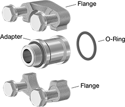
Combine an adapter with a two-piece pipe flange (sold separately) to build a customized flange connection. Also known as Code 61 or Code 62 split flanges, the two halves of the flange clamp around the adapter and bolt to another Code 61 or Code 62 flange. Flanges and adapters are 316 stainless steel which has excellent corrosion resistance.
NPTF (Dryseal) threads are compatible with NPT threads. UN/UNF (SAE Straight) threads are also known as O-ring boss threads; they have a gasket to prevent leaks.

- For Use With: Hydraulic Fluid
- Specifications Met: SAE J518, ISO 6162
316/316L Stainless Steel | ||||||
|---|---|---|---|---|---|---|
| Pipe Size | For SAE Flange Size | Dash Size | Max. Pressure | For Flanged Connection Surface | Each | |
NPTF | ||||||
| 3/4 | 3/4 | 12 | 5,000 psi @ 72° F | O-Ring Groove | 0000000 | 0000000 |
| 1 | 1 | 16 | 4,600 psi @ 72° F | O-Ring Groove | 0000000 | 000000 |
| 1 1/2 | 1 1/2 | 24 | 3,000 psi @ 72° F | O-Ring Groove | 0000000 | 000000 |
| 2 | 2 | 32 | 3,000 psi @ 72° F | O-Ring Groove | 0000000 | 000000 |

- For Use With: Hydraulic Fluid
- Specifications Met: SAE J518, ISO 6162

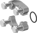
- For Use With: Hydraulic Fluid
- Specifications Met: SAE J518, ISO 6162
Flange | For Bolt | 316/316L Stainless Steel | |||||||||||
|---|---|---|---|---|---|---|---|---|---|---|---|---|---|
| SAE Flange Size | Dash Size | Max. Pressure | Ht. | Wd. | Dp. | Flanged Connection Surface | Mounting Hardware Included | For Bolt Dia. | Dia. | No. of | Ctr.-to-Ctr. | Each | |
Inch | |||||||||||||
| 3/4 | 12 | 5,000 psi @ 72° F | 2 9/16" | 2 1/16" | 7/8" | O-Ring Groove | Yes | 3/8" | 0.406" | 4 | 7/8", 1 7/8" | 0000000 | 0000000 |
| 1 | 16 | 4,600 psi @ 72° F | 2 3/4" | 2 5/16" | 15/16" | O-Ring Groove | Yes | 3/8" | 0.406" | 4 | 1.031", 2.062" | 0000000 | 000000 |
| 1 1/2 | 24 | 3,000 psi @ 72° F | 3 11/16" | 3 1/4" | 1" | O-Ring Groove | Yes | 1/2" | 0.531" | 4 | 1.406", 2 3/4" | 0000000 | 000000 |
| 2 | 32 | 3,000 psi @ 72° F | 4" | 3 13/16" | 1 1/32" | O-Ring Groove | Yes | 1/2" | 0.531" | 4 | 1.688", 3.062" | 0000000 | 000000 |
Metric | |||||||||||||
| 3/4 | 12 | 5,000 psi @ 72° F | 65mm | 52mm | 22mm | O-Ring Groove | Yes | 10mm | 10mm | 4 | 22mm, 48mm | 0000000 | 000000 |
| 1 | 16 | 4,600 psi @ 72° F | 70mm | 59mm | 24mm | O-Ring Groove | Yes | 10mm | 10mm | 4 | 26mm, 52mm | 0000000 | 000000 |
| 1 1/2 | 24 | 3,000 psi @ 72° F | 94mm | 83mm | 25mm | O-Ring Groove | Yes | 12mm | 13mm | 4 | 36mm, 70mm | 0000000 | 000000 |
| 2 | 32 | 3,000 psi @ 72° F | 102mm | 97mm | 26mm | O-Ring Groove | Yes | 12mm | 13mm | 4 | 43mm, 78mm | 0000000 | 000000 |
High-Pressure Steel Unthreaded SAE Pipe Flanges
Create an access point in a high-pressure hydraulic fluid line with these flanges. They are also known as Code 61 SAE hydraulic flanges. To connect, bolt a flange with an O-ring groove surface to a flange with a flat surface of the same size. Flanges are for use in noncorrosive environments.
Socket-connect flanges weld to pipe for a strong, permanent connection.
Cap flanges are also known as blind flanges.


- For Use With: Hydraulic Fluid
- Specifications Met: SAE J518, ISO 6162
Flange | Bolt Hole | ||||||||||||
|---|---|---|---|---|---|---|---|---|---|---|---|---|---|
| Pipe Size | SAE Flange Size | Dash Size | Max. Pressure | Ht. | Wd. | Dp. | Mounting Hardware Included | For Bolt Dia. | Dia. | No. of | Ctr.-to-Ctr. | Each | |
Inch | |||||||||||||
| 3/4 | 3/4 | 12 | 3,000 psi @ 72° F | 2 5/8" | 1 3/4" | 1" | Yes | 3/8" | 0.41" | 4 | 7/8", 1 7/8" | 0000000 | 000000 |
| 1 | 1 | 16 | 3,000 psi @ 72° F | 2 53/64" | 2" | 1" | Yes | 3/8" | 0.41" | 4 | 1.031", 2.062" | 0000000 | 00000 |
| 1 1/2 | 1 1/2 | 24 | 3,000 psi @ 72° F | 3 3/4" | 2 3/4" | 1 1/4" | Yes | 0.438" | 0.47" | 4 | 1.406", 2 3/4" | 000000 | 00000 |
| 2 | 2 | 32 | 3,000 psi @ 72° F | 4" | 3 1/4" | 1 1/2" | Yes | 1/2" | 0.53" | 4 | 1.688", 3.062" | 0000000 | 00000 |
Metric | |||||||||||||
| 1 1/2 | 1 1/2 | 24 | 3,000 psi @ 72° F | 95mm | 70mm | 32mm | Yes | 12mm | 13mm | 4 | 36mm, 70mm | 0000000 | 00000 |
| 2 | 2 | 32 | 3,000 psi @ 72° F | 102mm | 83mm | 38mm | Yes | 12mm | 13mm | 4 | 43mm, 78mm | 0000000 | 00000 |


- For Use With: Hydraulic Fluid
- Specifications Met: SAE J518, ISO 6162
Flange | Bolt Hole | |||||||||||
|---|---|---|---|---|---|---|---|---|---|---|---|---|
| SAE Flange Size | Dash Size | Max. Pressure | Ht. | Wd. | Dp. | Mounting Hardware Included | For Bolt Dia. | Dia. | No. of | Ctr.-to-Ctr. | Each | |
| 3/4 | 12 | 3,000 psi @ 72° F | 2 5/8" | 1 3/4" | 1" | Yes | 3/8" | 0.41" | 4 | 7/8", 1 7/8" | 000000 | 000000 |
| 1 | 16 | 3,000 psi @ 72° F | 2 53/64" | 2" | 1" | Yes | 3/8" | 0.41" | 4 | 1.031", 2.062" | 0000000 | 00000 |
| 1 1/2 | 24 | 3,000 psi @ 72° F | 3 3/4" | 2 3/4" | 1 1/4" | Yes | 0.438" | 0.47" | 4 | 1.406", 2 3/4" | 0000000 | 00000 |
| 2 | 32 | 3,000 psi @ 72° F | 4" | 3 1/4" | 1 1/2" | Yes | 1/2" | 0.53" | 4 | 1.688", 3.062" | 0000000 | 00000 |
High-Pressure Steel Threaded SAE Pipe Flanges
Also known as Code 61 SAE hydraulic flanges, these let you create an access point in a high-pressure hydraulic line. To connect, bolt flanges to equipment, or bolt a flange with an O-ring groove surface to a flange with a flat surface of the same size. Flanges are for use in noncorrosive environments.
NPTF (Dryseal) threads are compatible with NPT threads. UN/UNF (SAE Straight) threads are also known as O-ring boss threads.


- For Use With: Hydraulic Fluid
- Specifications Met: SAE J518, ISO 6162
Flange | Bolt Hole | |||||||||||||
|---|---|---|---|---|---|---|---|---|---|---|---|---|---|---|
| Pipe Size | Thread Size | Dash Size | SAE Flange Size | Max. Pressure | Ht. | Wd. | Dp. | Mounting Hardware Included | For Bolt Dia. | Dia. | No. of | Ctr.-to-Ctr. | Each | |
NPTF—Inch | ||||||||||||||
| 3/4 | __ | 12 | 3/4 | 3,000 psi @ 72° F | 2 5/8" | 1 3/4" | 1 1/4" | Yes | 3/8" | 0.41" | 4 | 0.875", 1.875" | 0000000 | 000000 |
| 1 | __ | 16 | 1 | 3,000 psi @ 72° F | 2 53/64" | 2" | 1 1/2" | Yes | 3/8" | 0.41" | 4 | 1.031", 2.063" | 0000000 | 00000 |
| 1 1/2 | __ | 24 | 1 1/2 | 3,000 psi @ 72° F | 3 3/4" | 2 3/4" | 1 3/4" | Yes | 0.438" | 0.53" | 4 | 1.406", 2.75" | 0000000 | 00000 |
| 2 | __ | 32 | 2 | 3,000 psi @ 72° F | 4" | 3 1/4" | 1 3/4" | Yes | 1/2" | 0.53" | 4 | 1.688", 3.063" | 0000000 | 00000 |
NPTF—Metric | ||||||||||||||
| 1 | __ | 16 | 1 | 3,000 psi @ 72° F | 72mm | 51mm | 38mm | Yes | 10mm | 10.5mm | 4 | 26mm, 52mm | 0000000 | 00000 |
| 2 | __ | 32 | 2 | 3,000 psi @ 72° F | 102mm | 83mm | 44mm | Yes | 12mm | 13.3mm | 4 | 43mm, 78mm | 0000000 | 00000 |
UN/UNF (SAE Straight)—Inch | ||||||||||||||
| __ | 1 5/16"-12 | 16 | 1 | 3,000 psi @ 72° F | 2 53/64" | 2" | 1 1/2" | Yes | 3/8" | 0.41" | 4 | 1.031", 2.063" | 0000000 | 00000 |
| __ | 1 7/8"-12 | 24 | 2 | 3,000 psi @ 72° F | 4" | 3 1/4" | 1 3/4" | Yes | 1/2" | 0.53" | 4 | 1.688", 3.063" | 0000000 | 00000 |
UN/UNF (SAE Straight)—Metric | ||||||||||||||
| __ | 1 7/8"-12 | 24 | 1 1/2 | 3,000 psi @ 72° F | 95mm | 70mm | 44mm | Yes | 12mm | 13.3mm | 4 | 36mm, 70mm | 0000000 | 00000 |
High-Pressure Steel Threaded SAE Two-Piece Pipe Flanges
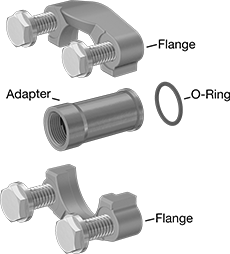
Combine an adapter with a two-piece pipe flange (sold separately) to build a customized flange connection. Also known as Code 61 or Code 62 split flanges, the two halves of the flange clamp around the adapter and bolt to another Code 61 or Code 62 flange. The adapters have NPTF (Dryseal) threads, so they’re compatible with NPT threads. Flanges and adapters should be used in noncorrosive environments.
- For Use With: Hydraulic Fluid
- Specifications Met: SAE J518, ISO 6162
| Pipe Size | Dash Size | For SAE Flange Size | Lg. | Max. Pressure | Each | |
NPTF | ||||||
|---|---|---|---|---|---|---|
| 3/4 | 12 | 3/4 | 3 1/8" | 6,000 psi @ 72° F | 0000000 | 000000 |
| 1 | 16 | 1 | 3" | 3,000 psi @ 72° F | 0000000 | 00000 |
| 1 | 16 | 1 | 3 5/8" | 6,000 psi @ 72° F | 0000000 | 00000 |
| 1 1/2 | 24 | 1 1/2 | 3 5/8" | 3,000 psi @ 72° F | 000000 | 000000 |
| 1 1/2 | 24 | 1 1/2 | 4 1/2" | 6,000 psi @ 72° F | 0000000 | 000000 |
| 2 | 32 | 2 | 3 5/8" | 3,000 psi @ 72° F | 0000000 | 000000 |
| 2 | 32 | 2 | 4 5/8" | 6,000 psi @ 72° F | 0000000 | 000000 |
- For Use With: Hydraulic Fluid
- Specifications Met: SAE J518, ISO 6162
Flange | Bolt Hole | ||||||||||||
|---|---|---|---|---|---|---|---|---|---|---|---|---|---|
| SAE Flange Size | Dash Size | Max. Pressure | Ht. | Wd. | Dp. | Flanged Connection Surface | Mounting Hardware Included | For Bolt Dia. | Dia. | No. of | Ctr.-to-Ctr. | Each | |
Inch | |||||||||||||
| 3/4 | 12 | 6,000 psi @ 72° F | 2 13/16" | 2 3/8" | 1 1/8" | O-Ring Groove | Yes | 3/8" | 0.41" | 4 | 15/16" , 2" | 0000000 | 000000 |
| 1 | 16 | 3,000 psi @ 72° F | 2 3/4" | 2 5/16" | 15/16" | O-Ring Groove | Yes | 3/8" | 0.41" | 4 | 1 1/32" , 2 1/16" | 0000000 | 00000 |
| 1 | 16 | 6,000 psi @ 72° F | 3 3/16" | 2 3/4" | 1 5/16" | O-Ring Groove | Yes | 0.438" | 0.47" | 4 | 1 3/32" , 2 1/4" | 0000000 | 00000 |
| 1 1/2 | 24 | 3,000 psi @ 72° F | 3 11/16" | 3 1/4" | 1" | O-Ring Groove | Yes | 0.438" | 0.47" | 4 | 1 13/32" , 2 3/4" | 000000 | 00000 |
| 1 1/2 | 24 | 6,000 psi @ 72° F | 4 7/16" | 3 3/4" | 1 11/16" | O-Ring Groove | Yes | 5/8" | 0.66" | 4 | 1 7/16" , 3 1/8" | 0000000 | 000000 |
| 2 | 32 | 3,000 psi @ 72° F | 4" | 3 13/16" | 1 1/32" | O-Ring Groove | Yes | 1/2" | 0.53" | 4 | 1 11/16" , 3 1/16" | 0000000 | 00000 |
| 2 | 32 | 6,000 psi @ 72° F | 5 1/4" | 4 1/2" | 2 1/16" | O-Ring Groove | Yes | 3/4" | 0.78" | 4 | 1 3/4" , 3 13/16" | 0000000 | 000000 |
Metric | |||||||||||||
| 3/4 | 12 | 6,000 psi @ 72° F | 71mm | 60mm | 29mm | O-Ring Groove | Yes | 10mm | 11mm | 4 | 24mm , 51mm | 0000000 | 00000 |
| 1 | 16 | 3,000 psi @ 72° F | 70mm | 59mm | 24mm | O-Ring Groove | Yes | 10mm | 11mm | 4 | 26mm , 52mm | 0000000 | 00000 |
| 1 | 16 | 6,000 psi @ 72° F | 81mm | 70mm | 33mm | O-Ring Groove | Yes | 12mm | 13mm | 4 | 28mm , 57mm | 0000000 | 00000 |
| 1 1/2 | 24 | 3,000 psi @ 72° F | 94mm | 83mm | 25mm | O-Ring Groove | Yes | 12mm | 13mm | 4 | 36mm , 70mm | 0000000 | 00000 |
| 1 1/2 | 24 | 6,000 psi @ 72° F | 113mm | 95mm | 43mm | O-Ring Groove | Yes | 16mm | 17mm | 4 | 37mm , 80mm | 000000 | 000000 |
| 2 | 32 | 3,000 psi @ 72° F | 102mm | 97mm | 26mm | O-Ring Groove | Yes | 12mm | 13mm | 4 | 43mm , 78mm | 0000000 | 00000 |
| 2 | 32 | 6,000 psi @ 72° F | 5 1/4" | 4 1/2" | 2 1/16" | O-Ring Groove | Yes | 20mm | 21mm | 4 | 1 3/4" , 3 13/16" | 0000000 | 000000 |
Easy-Access CPVC Pipe Flanges for Chemicals
- For Use With: Acetic Acid (10%), Calcium Chloride, Deionized Water, Hydrochloric Acid, Phosphoric Acid, Salt Water, Sodium Hydroxide, Sulfuric Acid (80%), Water
- Temperature Range: 32° to 200° F
- Specifications Met: ASTM D1784
- Pipe Nipples and Pipe: Use Schedule 80 CPVC Plastic
The grooved ends on these flanges connect to pipe with a clamp, so you can access your chemical process line for routine maintenance. They are also known as Victaulic flanges. Bolt two same-size flanges together with a gasket (sold separately). Flanges are CPVC, which has excellent chemical resistance to withstand a variety of salt solutions, acids, and other harsh substances. They are comparable to Corzan. Flanges meet ASTM D1784 specifications and testing requirements for material quality.
Warning: Never use plastic pipe flanges and pipe with compressed air or gas.
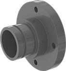
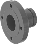
| Pipe Size | Flange OD | For Bolt Dia. | Bolt Hole Dia. | Number of Bolt Holes | Bolt Circle Dia. | Material | Color | Max. Pressure | Each | |
| 2 | 6" | 5/8" | 3/4" | 4 | 4 3/4" | CPVC Plastic | Light Gray | 150 psi @ 72° F | 0000000 | 0000000 |
| 3 | 7 1/2" | 5/8" | 3/4" | 4 | 6" | CPVC Plastic | Light Gray | 150 psi @ 72° F | 0000000 | 000000 |
| 4 | 9" | 5/8" | 3/4" | 8 | 7 1/2" | CPVC Plastic | Light Gray | 150 psi @ 72° F | 0000000 | 000000 |
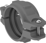
Clamp connectors let you connect CPVC grooved-end pipe fittings and pipe.
| For Pipe Size | For Pipe OD | Material | Color | Gasket Material | Max. Pressure | Specifications Met | Each | |
| 2 | 2 3/8" | Enamel-Coated Iron | Orange | EPDM Rubber | 300 psi @ 72° F | ASTM D1784, ASTM F441 | 0000000 | 000000 |
| 3 | 3 1/2" | Enamel-Coated Iron | Orange | EPDM Rubber | 300 psi @ 72° F | ASTM D1784, ASTM F441 | 0000000 | 00000 |
| 4 | 4 1/2" | Enamel-Coated Iron | Orange | EPDM Rubber | 300 psi @ 72° F | ASTM D1784, ASTM F441 | 0000000 | 000000 |
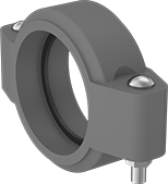
Clamp adapters let you connect CPVC grooved-end pipe fittings and pipe to metal grooved-end pipe fittings and pipe.
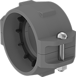
Clamp reducers allow you to connect CPVC grooved-end pipe fittings and pipe and transition from a larger pipe size to a smaller pipe size.
| For Pipe Size | For Pipe OD | Material | Color | Gasket Material | Max. Pressure | Specifications Met | Each | |
| 3 × 2 | 3 1/2" × 2 3/8" | Enamel-Coated Iron | Orange | EPDM Rubber | 300 psi @ 72° F | ASTM D1784, ASTM F441 | 0000000 | 000000 |
| 4 × 2 | 4 1/2" × 2 3/8" | Enamel-Coated Iron | Orange | EPDM Rubber | 300 psi @ 72° F | ASTM D1784, ASTM F441 | 0000000 | 000000 |
| 4 × 3 | 4 1/2" × 3 1/2" | Enamel-Coated Iron | Orange | EPDM Rubber | 300 psi @ 72° F | ASTM D1784, ASTM F441 | 0000000 | 000000 |


