


About Moment Loads
More
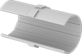
Sleeve Bearing Carriages and Guide Rails

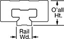
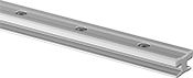
With fewer moving parts and no need for lubrication, sleeve bearing carriages perform better in dusty and wet environments than ball and roller bearing carriages. They're also better at handling impact and vibration.
Carriages with PTFE bearing operate with less friction than carriages with a polyethylene bearing.
Note: Each carriage can only be used with its corresponding guide rail. Load capacity is diminished when carriages are mounted upside down or on a vertical surface.
Zinc Carriages and PTFE Plastic Bearings | |||||||||||||||
|---|---|---|---|---|---|---|---|---|---|---|---|---|---|---|---|
Mounting | Anodized Aluminum Guide Rails | ||||||||||||||
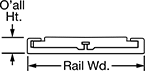
| For Rail Wd., mm | Static Load Cap., lbs. | O'all Ht., mm | Carriage Wd., mm | Carriage Lg., mm | Max. Temp., °F | No. of Holes | Hole Thread Size | Hole Thread Pitch, mm | Hole Dp., mm | Fasteners Included | Each | Rail Lengths, mm | Per mm | ||
| 7 | 45 | 8 | 17 | 23 | 190° | 4 | M2 | 0.4 | 6.5 | No | 9867K5 | 000000 | 9867K15 | 00000 | |
| 9 | 100 | 10 | 20 | 29 | 190° | 4 | M2 | 0.4 | 7.2 | No | 9867K6 | 00000 | 9867K16 | 000 | |
| 12 | 210 | 13 | 27 | 34 | 190° | 4 | M3 | 0.5 | 9.5 | No | 9867K7 | 00000 | 9867K17 | 000 | |
| 15 | 310 | 16 | 32 | 42 | 190° | 4 | M3 | 0.5 | 11 | No | 9867K1 | 00000 | 9867K11 | 000 | |
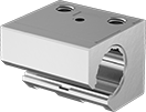
Low-Profile Sleeve Bearing Carriages and Guide Rails
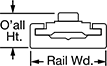
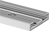
For applications with low clearance, these carriages protrude less than 5 mm above their rails. Use them for light to moderate loads, as well as frequent starting and stopping applications where tight tolerances are not required. Sleeve bearings allow them to outperform ball bearings in wet, dirty, and high-vibration environments. Mount in any orientation without affecting load capacity.
Brass Carriages and PTFE Plastic Bearings | ||||||||||||||||
|---|---|---|---|---|---|---|---|---|---|---|---|---|---|---|---|---|
Mounting | Anodized Aluminum Guide Rails | |||||||||||||||
| For Rail Wd., mm | Static Load Cap., lbs. | O'all Ht., mm | Carriage Wd., mm | Carriage Lg., mm | Max. Temp., °F | No. of Holes | Hole Thread Size | Hole Thread Pitch, mm | Hole Dp., mm | Fasteners Included | Each | Rail Lengths, mm | Per mm | |||
| A | 17 | 10 | 6 | 15 | 20 | 190° | 2 | M3 | 0.5 | 5 | No | 6723K9 | 00000 | 6723K5 | 00000 | |
Zinc Carriages and PTFE Plastic Bearings | |||||||||||||||||
|---|---|---|---|---|---|---|---|---|---|---|---|---|---|---|---|---|---|
Mounting | Anodized Aluminum Guide Rails | ||||||||||||||||
| For Rail Wd., mm | Static Load Cap., lbs. | O'all Ht., mm | Carriage Wd., mm | Carriage Lg., mm | Max. Temp., °F | No. of Holes | Hole Dia., mm | Hole Thread Size | Hole Thread Pitch, mm | Hole Dp., mm | Fasteners Included | Each | Rail Lengths, mm | Per mm | |||
| A | 40 | 150 | 9.5 | 34 | 50 | 190° | 2 | __ | M4 | 0.7 | 8 | No | 6723K12 | 000000 | 6723K3 | 00000 | |
| B | 27 | 110 | 9.5 | 24 | 40 | 190° | 2 | 4.5 | __ | __ | 5 | No | 6723K11 | 0000 | 6723K2 | 000 | |
| C | 80 | 220 | 12 | 72 | 80 | 190° | 4 | __ | M4 | 0.7 | 7 | No | 6723K13 | 00000 | 6723K4 | 000 | |
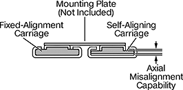
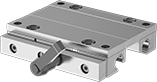
Self-Aligning Low-Profile Sleeve Bearing Carriages and Guide Rails
Compensate for rail misalignment in low-clearance applications with these carriages and guide rails. These carriages stick out less than 5 mm above their rails, giving them a low profile. They have a floating bearing that adjusts to correct misalignment between rails, so your carriages still move in tandem. Use them for light to moderate loads and applications with frequent starting and stopping where tight tolerances aren’t needed.
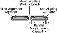
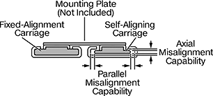
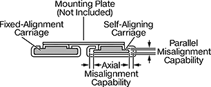
For a complete system, you’ll need a self-aligning carriage and rail on one side and a fixed-alignment carriage and rail on the other (all sold separately).
Carriages for axial rail misalignment compensate when the rails aren’t installed at the same exact height.
Carriages for parallel rail misalignment compensate when one rail is straight and the other is installed at a slight angle.
Carriages for axial/parallel rail misalignment compensate when the rails aren’t installed at the same exact height and also when one rail is straight while the other is installed at a slight angle.
Note: Each carriage can only be used with its corresponding guide rail. Load capacity is diminished when carriages are mounted upside down or on a vertical surface.
Zinc Carriages and PTFE Plastic Bearings | ||||||||||||||||||
|---|---|---|---|---|---|---|---|---|---|---|---|---|---|---|---|---|---|---|
Mounting | Anodized Aluminum Guide Rails | |||||||||||||||||
| For Rail Wd., mm | Static Load Cap., lbs. | Axial Misalignment Capability, mm | O'all Ht., mm | Carriage Wd., mm | Carriage Lg., mm | Max. Temp., °F | No. of Holes | Hole Dia, mm | Hole Thread Size | Hole Thread Pitch, mm | Hole Dp., mm | Fasteners Included | Each | Rail Lengths, mm | Per mm | |||
| A | 17 | 10 | 0.6 | 6 | 14 | 20 | 120° | 2 | __ | M3 | 0.5 | 4 | No | 4534N11 | 00000 | 6723K5 | 00000 | |
| A | 40 | 150 | 0.4 | 9.5 | 34 | 50 | 120° | 2 | __ | M4 | 0.7 | 6.1 | No | 4534N14 | 00000 | 6723K3 | 000 | |
| B | 27 | 110 | 0.5 | 9.5 | 24 | 40 | 120° | 2 | 4.5 | __ | __ | 3.8 | No | 4534N17 | 00000 | 6723K2 | 000 | |
| C | 80 | 220 | 0.6 | 12 | 72 | 80 | 120° | 4 | __ | M4 | 0.7 | 3.6 | No | 4534N21 | 00000 | 6723K4 | 000 | |
Zinc Carriages and PTFE Plastic Bearings | ||||||||||||||||||
|---|---|---|---|---|---|---|---|---|---|---|---|---|---|---|---|---|---|---|
Mounting | Anodized Aluminum Guide Rails | |||||||||||||||||
| For Rail Wd., mm | Static Load Cap., lbs. | Parallel Misalignment Capability, mm | O'all Ht., mm | Carriage Wd., mm | Carriage Lg., mm | Max. Temp., °F | No. of Holes | Hole Dia, mm | Hole Thread Size | Hole Thread Pitch, mm | Hole Dp., mm | Fasteners Included | Each | Rail Lengths, mm | Per mm | |||
| A | 17 | 10 | 0.5 | 6 | 14 | 20 | 120° | 2 | __ | M3 | 0.5 | 4 | No | 4534N12 | 00000 | 6723K5 | 00000 | |
| A | 40 | 150 | 0.8 | 9.5 | 34 | 50 | 120° | 2 | __ | M4 | 0.7 | 6.1 | No | 4534N15 | 00000 | 6723K3 | 000 | |
| B | 27 | 110 | 0.8 | 9.5 | 24 | 40 | 120° | 2 | 4.5 | __ | __ | 3.8 | No | 4534N18 | 00000 | 6723K2 | 000 | |
| C | 80 | 220 | 0.8 | 12 | 72 | 80 | 120° | 4 | __ | M4 | 0.7 | 3.6 | No | 4534N22 | 00000 | 6723K4 | 000 | |
Zinc Carriages and PTFE Plastic Bearings | |||||||||||||||||||
|---|---|---|---|---|---|---|---|---|---|---|---|---|---|---|---|---|---|---|---|
Misalignment Capability, mm | Mounting | Anodized Aluminum Guide Rails | |||||||||||||||||
| For Rail Wd., mm | Static Load Cap., lbs. | Axial | Parallel | O'all Ht., mm | Carriage Wd., mm | Carriage Lg., mm | Max. Temp., °F | No. of Holes | Hole Dia, mm | Hole Thread Size | Hole Thread Pitch, mm | Hole Dp., mm | Fasteners Included | Each | Rail Lengths, mm | Per mm | |||
| A | 17 | 10 | 0.6 | 0.5 | 6 | 14 | 20 | 120° | 2 | __ | M3 | 0.5 | 4 | No | 4534N13 | 00000 | 6723K5 | 00000 | |
| A | 40 | 150 | 0.4 | 0.8 | 9.5 | 34 | 50 | 120° | 2 | __ | M4 | 0.7 | 6.1 | No | 4534N16 | 00000 | 6723K3 | 000 | |
| B | 27 | 110 | 0.3 | 0.4 | 9.5 | 24 | 40 | 120° | 2 | 4.5 | __ | __ | 3.8 | No | 4534N19 | 00000 | 6723K2 | 000 | |
| C | 80 | 220 | 0.6 | 0.8 | 12 | 72 | 80 | 120° | 4 | __ | M4 | 0.7 | 3.6 | No | 4534N23 | 00000 | 6723K4 | 000 | |
Carriages and PTFE Plastic Bearings | |||||||||||||||||
|---|---|---|---|---|---|---|---|---|---|---|---|---|---|---|---|---|---|
Mounting | Anodized Aluminum Guide Rails | ||||||||||||||||
| For Rail Wd., mm | Static Load Cap., lbs. | O'all Ht., mm | Carriage Wd., mm | Carriage Lg., mm | Max. Temp., °F | No. of Holes | Hole Dia., mm | Hole Thread Size | Hole Thread Pitch, mm | Hole Dp., mm | Fasteners Included | Each | Rail Lengths, mm | Per mm | |||
Brass Carriages | |||||||||||||||||
| A | 17 | 10 | 8 | 15 | 20 | 190° | 2 | __ | M3 | 0.5 | 5 | No | 6723K9 | 00000 | 6723K5 | 00000 | |
Zinc Carriages | |||||||||||||||||
| A | 40 | 150 | 14.5 | 34 | 50 | 190° | 2 | __ | M4 | 0.7 | 8 | No | 6723K12 | 00000 | 6723K3 | 000 | |
| B | 27 | 110 | 10 | 24 | 40 | 190° | 2 | 4.5 | __ | __ | 5 | No | 6723K11 | 0000 | 6723K2 | 000 | |
| C | 80 | 220 | 12 | 72 | 80 | 190° | 4 | __ | M4 | 0.7 | 7 | No | 6723K13 | 00000 | 6723K4 | 000 | |
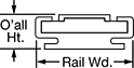
Extra-Wide Sleeve Bearing Carriages and Guide Rails
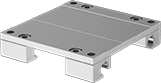
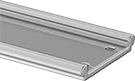
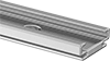
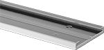
With a wide base and low-profile design, these carriages and guide rails stabilize moment (twisting) and off-center loads better than standard carriages and rails. Use in areas where multiple carriages or rails won't fit. Sleeve bearings allow them to outperform ball bearings in wet, dirty, and high-vibration environments. Mount in any orientation without affecting load capacity.
Zinc carriages are mildly corrosion resistant.
Zinc Carriages and PTFE Plastic Bearings | |||||||||||||||
|---|---|---|---|---|---|---|---|---|---|---|---|---|---|---|---|
Mounting | Anodized Aluminum Guide Rails | ||||||||||||||
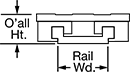
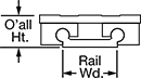
| For Rail Wd., mm | Static Load Cap., lbs. | O'all Ht., mm | Carriage Wd., mm | Carriage Lg., mm | Max. Temp., °F | No. of Holes | Hole Thread Size | Hole Thread Pitch, mm | Hole Dp., mm | Fasteners Included | Each | Rail Lengths, mm | Per mm | ||
Square | |||||||||||||||
| 27 | 370 | 18 | 54 | 60 | 190° | 4 | M4 | 0.7 | 15 | No | 6109K71 | 000000 | 6109K72 | 00000 | |
| 27 | 370 | 18 | 54 | 80 | 190° | 4 | M4 | 0.7 | 15 | No | 6109K201 | 00000 | 6109K72 | 000 | |
| 27 | 370 | 18 | 54 | 100 | 190° | 4 | M4 | 0.7 | 15 | No | 6109K202 | 00000 | 6109K72 | 000 | |
Round | |||||||||||||||
| 40 | 1,050 | 24 | 73 | 100 | 190° | 4 | M6 | 1 | 19 | No | 6109K41 | 00000 | 6109K42 | 000 | |
| 40 | 1,050 | 24 | 73 | 150 | 190° | 4 | M6 | 1 | 19 | No | 6109K203 | 00000 | 6109K42 | 000 | |
| 40 | 1,050 | 24 | 73 | 200 | 190° | 4 | M6 | 1 | 19 | No | 6109K204 | 00000 | 6109K42 | 000 | |
| 54 | 1,880 | 35 | 104 | 100 | 190° | 4 | M8 | 1.25 | 30 | No | 6109K209 | 000000 | 6109K82 | 000 | |
| 54 | 1,880 | 35 | 104 | 150 | 190° | 4 | M8 | 1.25 | 30 | No | 6109K211 | 000000 | 6109K82 | 000 | |
| 54 | 1,880 | 35 | 104 | 200 | 190° | 4 | M8 | 1.25 | 30 | No | 6109K212 | 000000 | 6109K82 | 000 | |
| 74 | 1,050 | 24 | 107 | 100 | 190° | 4 | M6 | 1 | 19 | No | 6109K51 | 00000 | 6109K52 | 000 | |
| 74 | 2,850 | 44 | 134 | 150 | 190° | 4 | M8 | 1.25 | 38 | No | 6109K61 | 000000 | 6109K62 | 000 | |
| 74 | 2,870 | 44 | 134 | 200 | 190° | 4 | M8 | 1.25 | 38 | No | 6109K216 | 000000 | 6109K62 | 000 | |
| 74 | 2,870 | 44 | 134 | 250 | 190° | 4 | M8 | 1.25 | 38 | No | 6109K217 | 000000 | 6109K62 | 000 | |
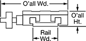
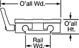
Locking Extra-Wide Sleeve Bearing Carriages and Guide Rails
A handle on the side of the carriage locks the carriage in place. Carriages have a wide base for stabilizing moment (twisting) and off-center loads better than standard sleeve bearing carriages. Use them in areas where multiple carriages or rails won't fit. The sleeve bearings allow them to outperform ball bearings in wet, dirty, and high-vibration environments. Mount in any orientation without affecting load capacity.
Zinc carriages are mildly corrosion resistant.
Zinc Carriages and PTFE Plastic Bearings | |||||||||||||||||||
|---|---|---|---|---|---|---|---|---|---|---|---|---|---|---|---|---|---|---|---|
Mounting | Anodized Aluminum Guide Rails | ||||||||||||||||||
| For Rail Wd., mm | Static Load Cap., lbs. | O'all Wd., mm | O'all Ht., mm | Carriage Wd., mm | Carriage Lg., mm | Handle Lg., mm | Max. Temp., °F | No. of Holes | Hole Thread Size | Hole Thread Pitch, mm | Hole Dp., mm | Fasteners Included | Rail Shape | Rail Shape | Each | Rail Lengths, mm | Per mm | ||
Square | |||||||||||||||||||
| 27 | 370 | 82 | 18 | 54 | 60 | 28 | 190° | 4 | M4 | 0.7 | 15 | No | __ | __ | 6109K111 | 0000000 | 6109K72 | 00000 | |
| 27 | 370 | 82 | 18 | 54 | 80 | 28 | 190° | 4 | M4 | 0.7 | 15 | No | __ | __ | 6109K257 | 00000 | 6109K72 | 000 | |
Round | |||||||||||||||||||
| 40 | 1,050 | 101 | 24 | 73 | 100 | 40 | 190° | 4 | M6 | 1 | 19 | No | Straight | Straight | 6109K121 | 000000 | 6109K42 | 000 | |
| 40 | 1,050 | 101 | 24 | 73 | 150 | 40 | 190° | 4 | M6 | 1 | 19 | No | Straight | Straight | 6109K258 | 000000 | 6109K42 | 000 | |
| 40 | 1,050 | 101 | 24 | 73 | 200 | 40 | 190° | 4 | M6 | 1 | 19 | No | Straight | Straight | 6109K259 | 000000 | 6109K42 | 000 | |
| 54 | 1,880 | 132 | 35 | 104 | 150 | 40 | 190° | 4 | M8 | 1.25 | 30 | No | __ | __ | 6109K263 | 000000 | 6109K82 | 000 | |
| 54 | 1,880 | 132 | 35 | 104 | 200 | 40 | 190° | 4 | M8 | 1.25 | 30 | No | __ | __ | 6109K264 | 000000 | 6109K82 | 000 | |
| 74 | 1,050 | 147 | 24 | 107 | 100 | 40 | 190° | 4 | M6 | 1 | 19 | No | __ | __ | 6109K131 | 000000 | 6109K52 | 000 | |
| 74 | 2,850 | 174 | 44 | 134 | 150 | 40 | 190° | 4 | M8 | 1.25 | 38 | No | __ | __ | 6109K141 | 000000 | 6109K62 | 000 | |
| 74 | 2,870 | 174 | 44 | 134 | 250 | 40 | 190° | 4 | M8 | 1.25 | 38 | No | __ | __ | 6109K265 | 000000 | 6109K62 | 000 | |