


About Moment Loads
More
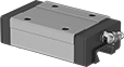
Ball Bearing Carriages and Guide Rails
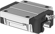


Operating with less friction than sleeve and roller bearing carriages, ball bearing carriages provide accurate movement and positioning in high-speed, high-load applications. However, they don’t hold up to dusty and wet environments as well as sleeve bearing carriages. Mount in any orientation without affecting load capacity. End seals keep lubricant in and dirt out. Add optional guide rail bellows to protect the rails from contaminants as carriages move across them.
Standard carriages are narrower than flanged carriages, making them better for confined spaces.
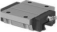
Flanged carriages have threaded mounting holes on the flanges rather than the carriage body, so you can fasten loads from both the top and bottom. When fastening from the bottom, use the mounting hole as a through-hole.
Add a hand brake to lock carriages in position. To install, fasten the brake to the same mounting surface as your carriage.
Mounting hole plugs protect mounting fasteners from corrosion. Carriage and guide rail systems for 5 mm-12 mm wide rails include mounting hole plugs with the guide rails.
Note: Each carriage can only be used with its corresponding guide rail.

For made-to-order guide rails, please specify the length of the rail (in 1 mm increments). The mounting holes will be centered along the rail.
Carriages | Guide Rails | Made-to-Order Guide Rails | Hand Brakes | Mounting Hole Plugs | |||||||||||||
|---|---|---|---|---|---|---|---|---|---|---|---|---|---|---|---|---|---|
| For Rail Wd., mm | Dynamic Load Cap., lbs. | O'all Ht., mm | Carriage Wd., mm | Carriage Lg., mm | Carriage Material | Each | Rail Lengths, mm | Per mm | Rail Lengths, mm | Per mm | Each | Each | |||||
Load Fastening From Top | |||||||||||||||||
| 45 | 18,450 | 70 | 86 | 139 | Steel | 0000000 | 0000000 | 0000000 | 00000 | 570-2,500 | 0000000 | 00000 | 0000000 | 0000000 | 000000 | 00000 | |
For made-to-order guide rails, please specify the length of the rail (in 1 mm increments). The mounting holes will be centered along the rail.
Carriages | Guide Rails | Made-to-Order Guide Rails | Hand Brakes | Mounting Hole Plugs | |||||||||||||
|---|---|---|---|---|---|---|---|---|---|---|---|---|---|---|---|---|---|
| For Rail Wd., mm | Dynamic Load Cap., lbs. | O'all Ht., mm | Carriage Wd., mm | Carriage Lg., mm | Carriage Material | Each | Rail Lengths, mm | Per mm | Rail Lengths, mm | Per mm | Each | Each | |||||
Load Fastening From Top and From Bottom | |||||||||||||||||
| 45 | 18,430 | 60 | 120 | 139 | Steel | 0000000 | 0000000 | 0000000 | 00000 | 570-2,500 | 0000000 | 00000 | 0000000 | 0000000 | 000000 | 00000 | |
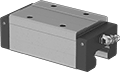
Horizontal-Mount Ball Bearing Carriages and Guide Rails
Designed for use on horizontal surfaces, the contact angle of the ball bearings on the rail allows these carriages to last longer than other carriages. The ball bearings provide accurate movement and positioning at high speeds under heavy loads. End seals keep lubricant in and dirt out. Add guide rail bellows to protect rails from contaminants as carriages move across them.
Standard carriages are narrower than flanged carriages, making them better for confined spaces.
Flanged carriages have through-holes for access when fastening loads.
Add a hand brake to lock carriages in position. To install, fasten the brake to the same mounting surface as your carriage.
Mounting hole plugs protect mounting fasteners from corrosion.
For made-to-order guide rails, please specify the length (in 1 mm increments). The mounting holes will be centered along the rail.
Steel Carriages | Steel Guide Rails | Made-to-Order Steel Guide Rails | Hand Brakes | Mounting Hole Plugs | ||||||||||||
|---|---|---|---|---|---|---|---|---|---|---|---|---|---|---|---|---|
| For Rail Wd., mm | Dynamic Load Cap., lbs. | O'all Ht., mm | Carriage Wd., mm | Carriage Lg., mm | Each | Rail Lengths, mm | Per mm | Rail Lengths, mm | Per mm | Each | Each | |||||
Load Fastening From Top | ||||||||||||||||
| 45 | 18,050 | 60 | 86 | 126 | 0000000 | 0000000 | 000000 | 00000 | 570-2,500 | 0000000 | 00000 | 0000000 | 0000000 | 000000 | 00000 | |
For made-to-order guide rails, please specify the length (in 1 mm increments). The mounting holes will be centered along the rail.
Steel Carriages | Steel Guide Rails | Made-to-Order Steel Guide Rails | Hand Brakes | Mounting Hole Plugs | ||||||||||||
|---|---|---|---|---|---|---|---|---|---|---|---|---|---|---|---|---|
| For Rail Wd., mm | Dynamic Load Cap., lbs. | O'all Ht., mm | Carriage Wd., mm | Carriage Lg., mm | Each | Rail Lengths, mm | Per mm | Rail Lengths, mm | Per mm | Each | Each | |||||
Load Fastening From Bottom | ||||||||||||||||
| 45 | 18,050 | 60 | 120 | 126 | 0000000 | 0000000 | 000000 | 00000 | 570-2,500 | 0000000 | 00000 | 0000000 | 0000000 | 000000 | 00000 | |
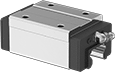
High-Cycle Ball Bearing Carriages and Guide Rails
A plastic cage surrounds the ball bearings and keeps them from colliding, so these carriages run for many cycles without needing maintenance. They also run quietly, since the bearings aren’t colliding. End seals keep dust from entering, and the cage traps lubricant around the bearings, reducing friction and heat buildup. Ball bearings provide accurate movement and positioning at high speeds under heavy loads. Mount in any orientation without affecting load capacity.
Standard carriages are narrower than flanged carriages, making them better for confined spaces.
Flanged carriages have threaded mounting holes on the flanges rather than the carriage body, so you can fasten loads from both the top and bottom. When fastening from the bottom, use the mounting hole as a through-hole.
Add a hand brake to lock carriages in position. To install, fasten the brake to the same mounting surface as your carriage.
Mounting hole plugs protect mounting fasteners from corrosion.
For made-to-order guide rails, please specify the length of the rail (in 1 mm increments). The mounting holes will be centered along the rail.
Carriages | Steel Guide Rails | Made-to-Order Steel Guide Rails | Hand Brakes | Mounting Hole Plugs | ||||||||||||
|---|---|---|---|---|---|---|---|---|---|---|---|---|---|---|---|---|
| For Rail Wd., mm | Dynamic Load Cap., lbs. | O'all Ht., mm | Carriage Wd., mm | Carriage Lg., mm | Each | Rail Lengths, mm | Per mm | Rail Lengths, mm | Per mm | Each | Each | |||||
Load Fastening From Top | ||||||||||||||||
| 45 | 18,600 | 70 | 86 | 140 | 0000000 | 0000000 | 0000000 | 00000 | 570-2,500 | 0000000 | 00000 | 0000000 | 0000000 | 000000 | 00000 | |
For made-to-order guide rails, please specify the length of the rail (in 1 mm increments). The mounting holes will be centered along the rail.
Carriages | Steel Guide Rails | Made-to-Order Steel Guide Rails | Hand Brakes | Mounting Hole Plugs | ||||||||||||
|---|---|---|---|---|---|---|---|---|---|---|---|---|---|---|---|---|
| For Rail Wd., mm | Dynamic Load Cap., lbs. | O'all Ht., mm | Carriage Wd., mm | Carriage Lg., mm | Each | Rail Lengths, mm | Per mm | Rail Lengths, mm | Per mm | Each | Each | |||||
Load Fastening From Top and From Bottom | ||||||||||||||||
| 45 | 18,600 | 60 | 120 | 140 | 0000000 | 0000000 | 0000000 | 00000 | 570-2,500 | 0000000 | 00000 | 0000000 | 0000000 | 000000 | 00000 | |
| 45 | 22,400 | 60 | 120 | 174 | 00000000 | 000000 | 0000000 | 000 | 570-2,500 | 0000000 | 000 | 0000000 | 000000 | 000000 | 0000 | |
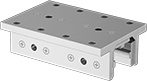
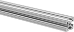
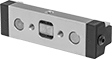
Sleeve Bearing Carriages for T-Slotted Framing
Mate with a T-slotted rail to add linear motion to your assembly. Carriages are suitable for washdown environments. Note: Carriages cannot be used upside down, vertically, or on their side.
T-slotted rails can be easily cut to length and drilled for mounting.
View additional T-slot hardware and accessories.
Hand brakes mount on the carriages to hold them in place on the rail. Carriages have mounting holes for the brakes.
End caps mount on the rails to prevent overtravel.
T-slot fasteners (sold separately) let you mount components to the carriages.
Carriages | Hand Brakes | T-Slot Fasteners | |||||||||||
|---|---|---|---|---|---|---|---|---|---|---|---|---|---|
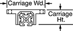
| For Rail Wd. | Static Load Cap., lbs. | Carriage Wd. | Carriage Lg. | Carriage Ht. | Bearing Material | Max. Temp., °F | Each | Each | Pkg. Qty. | Pkg. | |||
For Single Rail | |||||||||||||
| 45mm | 270 | 109mm | 80mm | 54mm | Acetal Plastic | 180° | 00000000 | 0000000 | 00000000 | 000000 | 4 | 00000000 | 00000 |
| 45mm | 540 | 109mm | 160mm | 54mm | Acetal Plastic | 180° | 00000000 | 000000 | 00000000 | 00000 | 4 | 00000000 | 0000 |
Side-Mount Track Roller Carriages and Guide Rails

Mount along a wall or other vertical surface.
Carriages with adjustable rollers can be adjusted for a snug or loose fit on the rail (also known as preload).
Carriages with wipers sweep away dust and other contaminants.
Carriages with Adjustable Rollers | Guide Rails | ||||||||||
|---|---|---|---|---|---|---|---|---|---|---|---|
| For Rail Wd., mm | Dynamic Load Cap., lbs. | O'all Ht., mm | Carriage Wd., mm | Carriage Lg., mm | Roller Dia., mm | Max. Temp., °F | Each | Rail Lengths, mm | Per mm | ||
Aluminum Carriages with Plastic Wipers and Steel Rollers | |||||||||||
| 45 | 590 | 33 | 38 | 117 | 24 | 175° | 00000000 | 0000000 | 0000000 | 00000 | |
| 45 | 590 | 33 | 38 | 152 | 24 | 175° | 00000000 | 000000 | 0000000 | 000 | |
| 45 | 890 | 33 | 38 | 190 | 24 | 175° | 00000000 | 000000 | 0000000 | 000 | |
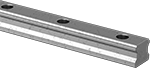
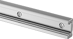
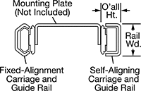
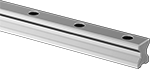
Self-Aligning Side-Mount Track Roller Carriages and Guide Rails
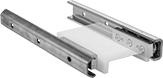
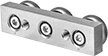
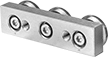
Create a self-aligning carriage and guide rail system to compensate for mounting surfaces that aren't parallel. The floating bearing in these carriages adjusts to correct misalignment between rails, so your carriages still move in tandem. A complete system includes a fixed-alignment carriage and rail on one side and a self-aligning carriage and rail on the other. All components are sold separately.
Carriages can be adjusted for a snug or loose fit on the rail (also known as preload). They have permanently lubricated rollers to save maintenance time and effort.
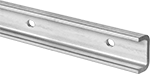
Fixed-alignment rails have a C-shaped profile that ensures the system travels in a straight line.
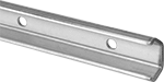
Self-aligning rails have a rectangular profile that allows the carriage to move freely from side to side to compensate for misalignment.
Zinc-Plated Steel Carriages with Adjustable Steel Rollers | |||||||||||
|---|---|---|---|---|---|---|---|---|---|---|---|
Misalignment Capability | Zinc-Plated Steel Guide Rails | ||||||||||
| For Rail Wd., mm | Dynamic Load Cap., lbs. | O'all Ht., mm | Roller Dia., mm | Axial, mm | Parallel, mm | Max. Temp., °F | Each | Rail Lengths, mm | Per mm | ||
Fixed Alignment | |||||||||||
| 45 | 390 | 38 | 35.6 | __ | 3.5 | 245° | 00000000 | 0000000 | 0000000 | 00000 | |
Self Aligning | |||||||||||
| 45 | 390 | 37.25 | 35 | 1.75 | 3.5 | 245° | 00000000 | 000000 | 0000000 | 000 | |
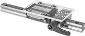
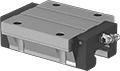
Locking High-Load Track Roller Carriages and Guide Rails
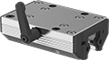
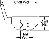
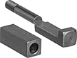
A handle on the side of the carriage locks the carriage in place. Made with needle-roller bearings, these track roller carriages have higher load capacities than other track roller carriages. Carriages can be adjusted for a snug or loose fit on the rail (also known as preload). Rollers are permanently lubricated to save maintenance time and effort.
Aluminum Carriages with Adjustable Steel Rollers | Anodized Aluminum Guide Rails | Replacement Clamp Jaw Kits | |||||||||||||
|---|---|---|---|---|---|---|---|---|---|---|---|---|---|---|---|
| For Rail Wd., mm | Dynamic Load Cap., lbs. | O'all Wd., mm | O'all Ht., mm | Carriage Wd., mm | Carriage Lg., mm | Handle Lg., mm | Max. Temp., °F | Max. Clamping Force, lbs. | Each | Rail Lengths, mm | Per mm | Each | |||
| 45 | 4,700 | 120 | 60 | 120 | 175 | 78 | 175° | 165 | 0000000 | 0000000 | 0000000 | 00000 | 0000000 | 0000000 | |
Guide Rail Bellows
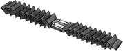
Also known as linear way covers, these bellows install on guide rails to protect the rails as carriages move across them. They have sealed seams to keep contaminants out. Air venting may be necessary in fast-cycling applications.
Mounting kits include hook-and-loop fasteners, mounting clips, mounting flanges, screws, and tape with adhesive on both sides to support different mounting options.
Bellows | |||||||||
|---|---|---|---|---|---|---|---|---|---|
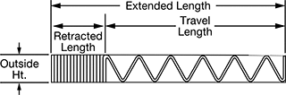
Length | Mounting Kits | ||||||||
| Extended | Retracted | Travel | Material | Material Thick. | Temp. Range, °F | Each | Each | ||
Protects Against Abrasive Grit, Coolant, Cutting Fluid, Dust, Metal Chips, Salt Water, Synthetic Oil, Water, Wood Chips | |||||||||
For 45 mm Rail Wd. (50 mm Outside Ht. × 88 mm Outside Wd.) | |||||||||
| 1 ft. | 15/16" | 11 1/16" | PVC-Coated Polyester Fabric | 0.01" | -40° to 160° | 000000000 | 0000000 | 00000000 | 000000 |
| 2 ft. | 1 7/8" | 22 1/8" | PVC-Coated Polyester Fabric | 0.01" | -40° to 160° | 000000000 | 000000 | 00000000 | 00000 |
| 3 ft. | 2 13/16" | 33 3/16" | PVC-Coated Polyester Fabric | 0.01" | -40° to 160° | 000000000 | 000000 | 00000000 | 00000 |
| 4 ft. | 3 3/4" | 44 1/4" | PVC-Coated Polyester Fabric | 0.01" | -40° to 160° | 000000000 | 000000 | 00000000 | 00000 |
| 6 ft. | 5 5/8" | 66 3/8" | PVC-Coated Polyester Fabric | 0.01" | -40° to 160° | 000000000 | 000000 | 00000000 | 00000 |
| 8 ft. | 7 1/2" | 88 1/2" | PVC-Coated Polyester Fabric | 0.01" | -40° to 160° | 000000000 | 000000 | 00000000 | 00000 |
| 12 ft. | 11 1/4" | 132 3/4" | PVC-Coated Polyester Fabric | 0.01" | -40° to 160° | 000000000 | 00000000 | 00000000 | 00000 |