


Filter by
Environment
System of Measurement
Pressure Set Point
For Use With
Measurement Unit
Fitting Connection
Maximum Switching Current @ Voltage
Connects To
Approximate Difference Between Set Point and Reset Point
Maximum Pressure
Connection Material
Thread Type
Maximum Pressure Differential
U.S.–Mexico–Canada Agreement (USMCA) Qualifying
DFARS Specialty Metals
Export Control Classification Number (ECCN)
Differential Pressure Switches with Dial Indicator for Liquids
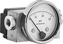 |
To check the difference in pressure between two points, these switches have a dial indicator that shows differential pressure in real time. The dial indicator operates independently of the switch. You’ll sometimes see these switches used to indicate a filter is clogged in a pump or cooling system. When the differential pressure reaches your setpoint, they turn equipment on and off, activate automated controls, or signal alarms. They are single pole, double throw (SPDT) and can be installed to turn one circuit from off to on or from on to off.
Rated NEMA 4X, these switches protect against dirt, washdown, and corrosion. They are also rated IP65 for protection from dust and rinsing. All are CSA certified, so they meet Canadian safety standards.
Pressure Set Point | Approx. Difference Between Set Point and Reset Point | Max. Input Pressure, psi | Accuracy | Max. Switching Current @ Voltage | Process Temp. Range, ° F | Connection Material | For Use With | Certification | Enclosure Rating | Hazardous Location Rating | Each | ||||||||||||||||||||||||||||||||||||||||||||||||||||||||||||||||||||||||||||||||||||||||
|---|---|---|---|---|---|---|---|---|---|---|---|---|---|---|---|---|---|---|---|---|---|---|---|---|---|---|---|---|---|---|---|---|---|---|---|---|---|---|---|---|---|---|---|---|---|---|---|---|---|---|---|---|---|---|---|---|---|---|---|---|---|---|---|---|---|---|---|---|---|---|---|---|---|---|---|---|---|---|---|---|---|---|---|---|---|---|---|---|---|---|---|---|---|---|---|---|---|---|---|
Screw-Terminal Wire Connection | |||||||||||||||||||||||||||||||||||||||||||||||||||||||||||||||||||||||||||||||||||||||||||||||||||
1/4 NPT Female Pipe Connection | |||||||||||||||||||||||||||||||||||||||||||||||||||||||||||||||||||||||||||||||||||||||||||||||||||
| 0 in. H₂O to 25 in. H₂O | 5 in. H₂O | 1,500 | ±2% | 250 mA @ 120V AC | -20 to 175 | Brass | Cleaning Solutions, Diesel Fuel, Gasoline, Hydraulic Fluid, Oil, Water | CSA Certified | IP65, NEMA 4X | NEC Class I Division 2 Groups A, B, C, D; NEC Class II Division 2 Groups F, G | 4587N11 | 0000000 | |||||||||||||||||||||||||||||||||||||||||||||||||||||||||||||||||||||||||||||||||||||||
| 0 psi to 1 psi | 0.2 psi | 1,500 | ±2% | 250 mA @ 120V AC | -20 to 175 | Brass | Cleaning Solutions, Diesel Fuel, Gasoline, Hydraulic Fluid, Oil, Water | CSA Certified | IP65, NEMA 4X | NEC Class I Division 2 Groups A, B, C, D; NEC Class II Division 2 Groups F, G | 4587N12 | 000000 | |||||||||||||||||||||||||||||||||||||||||||||||||||||||||||||||||||||||||||||||||||||||
| 0 psi to 5 psi | 1 psi | 1,500 | ±2% | 250 mA @ 120V AC | -20 to 175 | Brass | Cleaning Solutions, Diesel Fuel, Gasoline, Hydraulic Fluid, Oil, Water | CSA Certified | IP65, NEMA 4X | NEC Class I Division 2 Groups A, B, C, D; NEC Class II Division 2 Groups F, G | 4587N13 | 000000 | |||||||||||||||||||||||||||||||||||||||||||||||||||||||||||||||||||||||||||||||||||||||
| 3 psi to 15 psi | 3 psi | 5,000 | ±2% | 250 mA @ 120V AC | -40 to 175 | Brass | Cleaning Solutions, Diesel Fuel, Gasoline, Hydraulic Fluid, Oil, Water | CSA Certified | IP65, NEMA 4X | NEC Class I Division 2 Groups A, B, C, D; NEC Class II Division 2 Groups F, G | 40945K81 | 000000 | |||||||||||||||||||||||||||||||||||||||||||||||||||||||||||||||||||||||||||||||||||||||
| 6 psi to 30 psi | 6 psi | 5,000 | ±2% | 250 mA @ 120V AC | -40 to 175 | Brass | Cleaning Solutions, Diesel Fuel, Gasoline, Hydraulic Fluid, Oil, Water | CSA Certified | IP65, NEMA 4X | NEC Class I Division 2 Groups A, B, C, D; NEC Class II Division 2 Groups F, G | 40945K82 | 000000 | |||||||||||||||||||||||||||||||||||||||||||||||||||||||||||||||||||||||||||||||||||||||
| 10 psi to 50 psi | 10 psi | 5,000 | ±2% | 250 mA @ 120V AC | -40 to 175 | Brass | Cleaning Solutions, Diesel Fuel, Gasoline, Hydraulic Fluid, Oil, Water | CSA Certified | IP65, NEMA 4X | NEC Class I Division 2 Groups A, B, C, D; NEC Class II Division 2 Groups F, G | 40945K83 | 000000 | |||||||||||||||||||||||||||||||||||||||||||||||||||||||||||||||||||||||||||||||||||||||
Hazardous Location Differential Pressure Switches for Air
 |
With an explosion-proof enclosure that meets NEMA 7 and 9 standards for hazardous locations, these switches were tested and verified by UL for use where explosive gas or dust may be present. Often used with ovens, dryers, and HVAC systems, they can indicate a filter is clogged or help maintain a certain air pressure. These switches turn equipment on and off, activate automated controls, or signal alarms when the differential pressure reaches your setpoint. They are single pole, double throw (SPDT) and can be installed to turn one circuit from off to on or from on to off.
In addition to being UL listed, these switches are CE marked and FM approved, so they also meet European safety standards. They also are IP and NEMA rated for use outdoors and protect against dust and splashing water.
When measuring pressure in ductwork, pair them with a static pressure probe.
Pressure Set Point Range | Approx. Difference Between Set Point and Reset Point | Max. Input Pressure | Accuracy | Max. Switching Current @ Voltage | Process Temp. Range, ° F | Connection Material | For Use With | Enclosure Rating | Hazardous Location Rating | Each | |||||||||||||||||||||||||||||||||||||||||||||||||||||||||||||||||||||||||||||||||||||||||
|---|---|---|---|---|---|---|---|---|---|---|---|---|---|---|---|---|---|---|---|---|---|---|---|---|---|---|---|---|---|---|---|---|---|---|---|---|---|---|---|---|---|---|---|---|---|---|---|---|---|---|---|---|---|---|---|---|---|---|---|---|---|---|---|---|---|---|---|---|---|---|---|---|---|---|---|---|---|---|---|---|---|---|---|---|---|---|---|---|---|---|---|---|---|---|---|---|---|---|---|
Screw-Terminal Wire Connection | |||||||||||||||||||||||||||||||||||||||||||||||||||||||||||||||||||||||||||||||||||||||||||||||||||
1/8 NPT Female Pipe Connection | |||||||||||||||||||||||||||||||||||||||||||||||||||||||||||||||||||||||||||||||||||||||||||||||||||
| 0.07 in. H₂O to 0.15 in. H₂O | 0.13 in. H₂O | 45 in. H₂O | ±2% | 15 amp @ 125V AC 15 amp @ 250V AC 15 amp @ 480V AC | -40 to 140 | Aluminum | Air | IP54, NEMA 3, NEMA 7, NEMA 9 | NEC Class I Divisions 1, 2 Groups C, D; NEC Class II Divisions 1, 2 Groups E, F, G | 5114N11 | 0000000 | ||||||||||||||||||||||||||||||||||||||||||||||||||||||||||||||||||||||||||||||||||||||||
| 0.15 in. H₂O to 0.5 in. H₂O | 0.05 in. H₂O | 45 in. H₂O | ±2% | 15 amp @ 125V AC 15 amp @ 250V AC 15 amp @ 480V AC | -40 to 140 | Aluminum | Air | IP54, NEMA 3, NEMA 7, NEMA 9 | NEC Class I Divisions 1, 2 Groups C, D; NEC Class II Divisions 1, 2 Groups E, F, G | 5114N12 | 000000 | ||||||||||||||||||||||||||||||||||||||||||||||||||||||||||||||||||||||||||||||||||||||||
| 0.4 in. H₂O to 1.6 in. H₂O | 0.18 in. H₂O | 45 in. H₂O | ±2% | 15 amp @ 125V AC 15 amp @ 250V AC 15 amp @ 480V AC | -40 to 140 | Aluminum | Air | IP54, NEMA 3, NEMA 7, NEMA 9 | NEC Class I Divisions 1, 2 Groups C, D; NEC Class II Divisions 1, 2 Groups E, F, G | 5114N13 | 000000 | ||||||||||||||||||||||||||||||||||||||||||||||||||||||||||||||||||||||||||||||||||||||||
| 1.4 in. H₂O to 5.5 in. H₂O | 0.35 in. H₂O | 45 in. H₂O | ±2% | 15 amp @ 125V AC 15 amp @ 250V AC 15 amp @ 480V AC | -40 to 140 | Aluminum | Air | IP54, NEMA 3, NEMA 7, NEMA 9 | NEC Class I Divisions 1, 2 Groups C, D; NEC Class II Divisions 1, 2 Groups E, F, G | 5114N14 | 000000 | ||||||||||||||||||||||||||||||||||||||||||||||||||||||||||||||||||||||||||||||||||||||||
| 3 in. H₂O to 11 in. H₂O | 0.45 in. H₂O | 45 in. H₂O | ±2% | 15 amp @ 125V AC 15 amp @ 250V AC 15 amp @ 480V AC | -40 to 140 | Aluminum | Air | IP54, NEMA 3, NEMA 7, NEMA 9 | NEC Class I Divisions 1, 2 Groups C, D; NEC Class II Divisions 1, 2 Groups E, F, G | 5114N15 | 000000 | ||||||||||||||||||||||||||||||||||||||||||||||||||||||||||||||||||||||||||||||||||||||||
| 4 in. H₂O to 20 in. H₂O | 0.5 in. H₂O | 45 in. H₂O | ±2% | 15 amp @ 125V AC 15 amp @ 250V AC 15 amp @ 480V AC | -40 to 140 | Aluminum | Air | IP54, NEMA 3, NEMA 7, NEMA 9 | NEC Class I Divisions 1, 2 Groups C, D; NEC Class II Divisions 1, 2 Groups E, F, G | 5114N16 | 000000 | ||||||||||||||||||||||||||||||||||||||||||||||||||||||||||||||||||||||||||||||||||||||||
| 0.5 psi to 2 psi | 0.3 psi | 35 psi | ±2% | 15 amp @ 125V AC 15 amp @ 250V AC 15 amp @ 480V AC | -40 to 140 | Aluminum | Air | IP54, NEMA 3, NEMA 7, NEMA 9 | NEC Class I Divisions 1, 2 Groups C, D; NEC Class II Divisions 1, 2 Groups E, F, G | 5114N17 | 000000 | ||||||||||||||||||||||||||||||||||||||||||||||||||||||||||||||||||||||||||||||||||||||||
| 1.5 psi to 8 psi | 1 psi | 35 psi | ±2% | 15 amp @ 125V AC 15 amp @ 250V AC 15 amp @ 480V AC | 0 to 140 | Aluminum | Air | IP54, NEMA 3, NEMA 7, NEMA 9 | NEC Class I Divisions 1, 2 Groups C, D; NEC Class II Divisions 1, 2 Groups E, F, G | 5114N18 | 000000 | ||||||||||||||||||||||||||||||||||||||||||||||||||||||||||||||||||||||||||||||||||||||||
| 3 psi to 15 psi | 0.9 psi | 35 psi | ±2% | 15 amp @ 125V AC 15 amp @ 250V AC 15 amp @ 480V AC | 0 to 140 | Aluminum | Air | IP54, NEMA 3, NEMA 7, NEMA 9 | NEC Class I Divisions 1, 2 Groups C, D; NEC Class II Divisions 1, 2 Groups E, F, G | 5114N19 | 000000 | ||||||||||||||||||||||||||||||||||||||||||||||||||||||||||||||||||||||||||||||||||||||||
| 4 psi to 25 psi | 0.7 psi | 35 psi | ±2% | 15 amp @ 125V AC 15 amp @ 250V AC 15 amp @ 480V AC | 0 to 140 | Aluminum | Air | IP54, NEMA 3, NEMA 7, NEMA 9 | NEC Class I Divisions 1, 2 Groups C, D; NEC Class II Divisions 1, 2 Groups E, F, G | 5114N21 | 000000 | ||||||||||||||||||||||||||||||||||||||||||||||||||||||||||||||||||||||||||||||||||||||||
| 15 psi to 50 psi | 1.25 psi | 70 psi | ±2% | 15 amp @ 125V AC 15 amp @ 250V AC 15 amp @ 480V AC | 0 to 140 | Aluminum | Air | IP54, NEMA 3, NEMA 7, NEMA 9 | NEC Class I Divisions 1, 2 Groups C, D; NEC Class II Divisions 1, 2 Groups E, F, G | 5114N22 | 000000 | ||||||||||||||||||||||||||||||||||||||||||||||||||||||||||||||||||||||||||||||||||||||||
Hazardous Location Differential Pressure Switches for Liquids
 |
Tested and verified by UL and C-UL for use where explosive dust or gas are present, these switches have an explosion-proof enclosure that meets NEMA 7 and 9 standards for hazardous locations. They are often used to indicate a filter is clogged in a pump or cooling system. When the differential pressure reaches your setpoint, these switches can turn equipment on and off, activate automated controls, or signal alarms. They are single pole, double throw (SPDT) and can be installed to turn one circuit from off to on or from on to off.
In addition to being UL and C-UL listed, these switches are CE marked, so they also meet European safety standards. All switches are IP and NEMA rated for use outdoors and to protect against some corrosion, dust, and washdowns.
Pressure Set Point Range | Approx. Difference Between Set Point and Reset Point | Max. Input Pressure, psi | Accuracy | Max. Switching Current @ Voltage | Process Temp. Range, ° F | Connection Material | For Use With | Enclosure Rating | Hazardous Location Rating | Each | |||||||||||||||||||||||||||||||||||||||||||||||||||||||||||||||||||||||||||||||||||||||||
|---|---|---|---|---|---|---|---|---|---|---|---|---|---|---|---|---|---|---|---|---|---|---|---|---|---|---|---|---|---|---|---|---|---|---|---|---|---|---|---|---|---|---|---|---|---|---|---|---|---|---|---|---|---|---|---|---|---|---|---|---|---|---|---|---|---|---|---|---|---|---|---|---|---|---|---|---|---|---|---|---|---|---|---|---|---|---|---|---|---|---|---|---|---|---|---|---|---|---|---|
Screw-Terminal Wire Connection | |||||||||||||||||||||||||||||||||||||||||||||||||||||||||||||||||||||||||||||||||||||||||||||||||||
1/4 NPT Female Pipe Connection | |||||||||||||||||||||||||||||||||||||||||||||||||||||||||||||||||||||||||||||||||||||||||||||||||||
| 5 in. H₂O to 80 in. H₂O | 2.5 in. H₂O | 225 | ±0.5% | 15 amp @ 125V AC 15 amp @ 250V AC 15 amp @ 480V AC 2 amp @ 30V DC 1 amp @ 48V DC 500 mA @ 125V DC | -10 to 200 | Aluminum | Diesel Fuel, Gasoline, Petroleum-Based Hydraulic Oil, Water | NEMA 4X, NEMA 7, NEMA 9, IP66 | NEC Class I Divisions 1, 2 Groups B, C, D; NEC Class II Divisions 1, 2 Groups E, F, G | 5214N11 | 0000000 | ||||||||||||||||||||||||||||||||||||||||||||||||||||||||||||||||||||||||||||||||||||||||
| 2 psi to 20 psi | 0.2 psi | 225 | ±0.5% | 15 amp @ 125V AC 15 amp @ 250V AC 15 amp @ 480V AC 2 amp @ 30V DC 1 amp @ 48V DC 500 mA @ 125V DC | -10 to 200 | Aluminum | Diesel Fuel, Gasoline, Petroleum-Based Hydraulic Oil, Water | NEMA 4X, NEMA 7, NEMA 9, IP66 | NEC Class I Divisions 1, 2 Groups B, C, D; NEC Class II Divisions 1, 2 Groups E, F, G | 5214N12 | 000000 | ||||||||||||||||||||||||||||||||||||||||||||||||||||||||||||||||||||||||||||||||||||||||
| 3 psi to 30 psi | 0.25 psi | 225 | ±0.5% | 15 amp @ 125V AC 15 amp @ 250V AC 15 amp @ 480V AC 2 amp @ 30V DC 1 amp @ 48V DC 500 mA @ 125V DC | -10 to 200 | Aluminum | Diesel Fuel, Gasoline, Petroleum-Based Hydraulic Oil, Water | NEMA 4X, NEMA 7, NEMA 9, IP66 | NEC Class I Divisions 1, 2 Groups B, C, D; NEC Class II Divisions 1, 2 Groups E, F, G | 5214N13 | 000000 | ||||||||||||||||||||||||||||||||||||||||||||||||||||||||||||||||||||||||||||||||||||||||
| 10 psi to 100 psi | 0.6 psi | 225 | ±0.5% | 15 amp @ 125V AC 15 amp @ 250V AC 15 amp @ 480V AC 2 amp @ 30V DC 1 amp @ 48V DC 500 mA @ 125V DC | -10 to 200 | Aluminum | Diesel Fuel, Gasoline, Petroleum-Based Hydraulic Oil, Water | NEMA 4X, NEMA 7, NEMA 9, IP66 | NEC Class I Divisions 1, 2 Groups B, C, D; NEC Class II Divisions 1, 2 Groups E, F, G | 5214N14 | 000000 | ||||||||||||||||||||||||||||||||||||||||||||||||||||||||||||||||||||||||||||||||||||||||
Differential Pressure Transmitters with Dial Indicator for Liquids
 |
Mounting Holes | |||||||||||||||||||||||||||||||||||||||||||||||||||||||||||||||||||||||||||||||||||||||||||||||||||
|---|---|---|---|---|---|---|---|---|---|---|---|---|---|---|---|---|---|---|---|---|---|---|---|---|---|---|---|---|---|---|---|---|---|---|---|---|---|---|---|---|---|---|---|---|---|---|---|---|---|---|---|---|---|---|---|---|---|---|---|---|---|---|---|---|---|---|---|---|---|---|---|---|---|---|---|---|---|---|---|---|---|---|---|---|---|---|---|---|---|---|---|---|---|---|---|---|---|---|---|
Pressure Differential | Max. Input Pressure, psi | Input Voltage, V DC | Pipe Size | Mounting Hardware Included | Dia. | No. of | Ht. | Wd. | Enclosure Rating | Hazardous Location Rating | For Use With | Accuracy | Pipe Connection | Housing Material | Temp. Range, ° F | Each | |||||||||||||||||||||||||||||||||||||||||||||||||||||||||||||||||||||||||||||||||||
4 to 20 mA, 0 to 5V DC Output Signal—Screw Terminals | |||||||||||||||||||||||||||||||||||||||||||||||||||||||||||||||||||||||||||||||||||||||||||||||||||
| 0 in. H₂O to 25 in. H₂O | 1,500 | 9 to 35 | 1/4 | No | 3/16" | 2 | 2" | 4 7/16" | IP65, NEMA 4X | NEC Class I Division 2 Groups A, B, C, D NEC Class II Divisions 1, 2 Groups F, G | Diesel Fuel, Gasoline, Hydraulic Fluid, Water | ±2% | NPT Female | Brass | -20 to 200 | 6060N11 | 0000000 | ||||||||||||||||||||||||||||||||||||||||||||||||||||||||||||||||||||||||||||||||||
| 0 psi to 1 psi | 1,500 | 9 to 35 | 1/4 | No | 3/16" | 2 | 2" | 4 7/16" | IP65, NEMA 4X | NEC Class I Division 2 Groups A, B, C, D NEC Class II Divisions 1, 2 Groups F, G | Diesel Fuel, Gasoline, Hydraulic Fluid, Water | ±2% | NPT Female | Brass | -20 to 200 | 6060N12 | 000000 | ||||||||||||||||||||||||||||||||||||||||||||||||||||||||||||||||||||||||||||||||||
| 0 psi to 5 psi | 1,500 | 9 to 35 | 1/4 | No | 3/16" | 2 | 2" | 4 7/16" | IP65, NEMA 4X | NEC Class I Division 2 Groups A, B, C, D NEC Class II Divisions 1, 2 Groups F, G | Diesel Fuel, Gasoline, Hydraulic Fluid, Water | ±2% | NPT Female | Brass | -20 to 200 | 6060N13 | 000000 | ||||||||||||||||||||||||||||||||||||||||||||||||||||||||||||||||||||||||||||||||||
| 0 psi to 15 psi | 5,000 | 9 to 35 | 1/4 | No | 3/16" | 2 | 2 5/8" | 2 15/16" | IP65, NEMA 4X | NEC Class I Division 2 Groups A, B, C, D NEC Class II Divisions 1, 2 Groups F, G | Diesel Fuel, Gasoline, Hydraulic Fluid, Water | ±2% | NPT Female | Brass | -20 to 200 | 6060N14 | 000000 | ||||||||||||||||||||||||||||||||||||||||||||||||||||||||||||||||||||||||||||||||||
| 0 psi to 30 psi | 5,000 | 9 to 35 | 1/4 | No | 3/16" | 2 | 2 5/8" | 2 15/16" | IP65, NEMA 4X | NEC Class I Division 2 Groups A, B, C, D NEC Class II Divisions 1, 2 Groups F, G | Diesel Fuel, Gasoline, Hydraulic Fluid, Water | ±2% | NPT Female | Brass | -20 to 200 | 6060N15 | 000000 | ||||||||||||||||||||||||||||||||||||||||||||||||||||||||||||||||||||||||||||||||||
| 0 psi to 50 psi | 5,000 | 9 to 35 | 1/4 | No | 3/16" | 2 | 2 5/8" | 2 15/16" | IP65, NEMA 4X | NEC Class I Division 2 Groups A, B, C, D NEC Class II Divisions 1, 2 Groups F, G | Diesel Fuel, Gasoline, Hydraulic Fluid, Water | ±2% | NPT Female | Brass | -20 to 200 | 6060N16 | 000000 | ||||||||||||||||||||||||||||||||||||||||||||||||||||||||||||||||||||||||||||||||||
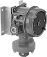
Hazardous Location Easy-Setup Differential Pressure Transmitters
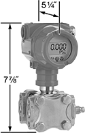 |
Safe for use in environments where flammable gases and vapors are present, these transmitters measure the difference in pressure between two process lines without needing to program your receiving device to correct for errors. They meet NEC safety standards for protection against an explosion. These transmitters automatically compensate for errors caused by vibration and temperature changes. Set the pressure range with the keypad, select the unit of measure, and zero the transmitter. They convert differential pressure into an electrical signal that can be interpreted by receiving devices, such as remote displays, programmable logic controllers (PLCs), and motor speed controls, to monitor pressure or control equipment. You’ll often see them used to indicate a clogged filter or help maintain a certain pressure in heat exchangers, chillers, HVAC systems, and pumps. Rated IP66 and NEMA 4X, they protect against dirt, dust, corrosion, weather, and washdowns, and the hastelloy nickel connection protects against harsh chemicals.
Transmitters will only provide accurate readings within the rated pressure range. Most often, these transmitters connect using two wires. The same wire that sends a signal to the receiver also powers the transmitter. Current doesn’t lose signal over long distances and isn’t affected by electrical interference from other devices. Three- and four-wire configurations are also possible.
Mounting Holes | Connection | ||||||||||||||||||||||||||||||||||||||||||||||||||||||||||||||||||||||||||||||||||||||||||||||||||
|---|---|---|---|---|---|---|---|---|---|---|---|---|---|---|---|---|---|---|---|---|---|---|---|---|---|---|---|---|---|---|---|---|---|---|---|---|---|---|---|---|---|---|---|---|---|---|---|---|---|---|---|---|---|---|---|---|---|---|---|---|---|---|---|---|---|---|---|---|---|---|---|---|---|---|---|---|---|---|---|---|---|---|---|---|---|---|---|---|---|---|---|---|---|---|---|---|---|---|---|
Pressure Differential | Max. Input Pressure, psi | Input Voltage, V DC | Pipe Size | Mounting Hardware Included | Dia. | No. of | Ht. | Wd. | Communication Protocol | Enclosure Rating | For Use With | Accuracy | Pipe | Fitting | Material | Temp. Range, ° F | Each | ||||||||||||||||||||||||||||||||||||||||||||||||||||||||||||||||||||||||||||||||||
4 to 20 mA Output Signal—Screw Terminals | |||||||||||||||||||||||||||||||||||||||||||||||||||||||||||||||||||||||||||||||||||||||||||||||||||
NEC Class I Divisions 1, 2 Groups A, B, C, D | |||||||||||||||||||||||||||||||||||||||||||||||||||||||||||||||||||||||||||||||||||||||||||||||||||
| 0 in. H₂O to 25 in. H₂O | 3,625 | 11 to 55 | 1/4 | No | 7/16" | 8 | 7 7/8" | 5 1/4" | HART | IP66, NEMA 4X | Air, Diesel Fuel, Gasoline, Hydraulic Fluid, Water | ±0.075% | NPT Female | Threaded | Hastelloy Nickel | -40 to 185 | 8876N11 | 000000000 | |||||||||||||||||||||||||||||||||||||||||||||||||||||||||||||||||||||||||||||||||
| 0 in. H₂O to 200 in. H₂O | 5,800 | 11 to 55 | 1/4 | No | 7/16" | 8 | 7 7/8" | 5 1/4" | HART | IP66, NEMA 4X | Air, Diesel Fuel, Gasoline, Hydraulic Fluid, Water | ±0.075% | NPT Female | Threaded | Hastelloy Nickel | -40 to 185 | 8876N22 | 00000000 | |||||||||||||||||||||||||||||||||||||||||||||||||||||||||||||||||||||||||||||||||
| 0 in. H₂O to 1,000 in. H₂O | 5,800 | 11 to 55 | 1/4 | No | 7/16" | 8 | 7 7/8" | 5 1/4" | HART | IP66, NEMA 4X | Air, Diesel Fuel, Gasoline, Hydraulic Fluid, Water | ±0.075% | NPT Female | Threaded | Hastelloy Nickel | -40 to 185 | 8876N13 | 00000000 | |||||||||||||||||||||||||||||||||||||||||||||||||||||||||||||||||||||||||||||||||
| 0 psi to 150 psi | 5,800 | 11 to 55 | 1/4 | No | 7/16" | 8 | 7 7/8" | 5 1/4" | HART | IP66, NEMA 4X | Air, Diesel Fuel, Gasoline, Hydraulic Fluid, Water | ±0.075% | NPT Female | Threaded | Hastelloy Nickel | -40 to 185 | 8876N14 | 00000000 | |||||||||||||||||||||||||||||||||||||||||||||||||||||||||||||||||||||||||||||||||
| 0 psi to 450 psi | 5,800 | 11 to 55 | 1/4 | No | 7/16" | 8 | 7 7/8" | 5 1/4" | HART | IP66, NEMA 4X | Air, Diesel Fuel, Gasoline, Hydraulic Fluid, Water | ±0.075% | NPT Female | Threaded | Hastelloy Nickel | -40 to 185 | 8876N15 | 00000000 | |||||||||||||||||||||||||||||||||||||||||||||||||||||||||||||||||||||||||||||||||
| 0 psi to 1,500 psi | 5,800 | 11 to 55 | 1/4 | No | 7/16" | 8 | 7 7/8" | 5 1/4" | HART | IP66, NEMA 4X | Air, Diesel Fuel, Gasoline, Hydraulic Fluid, Water | ±0.075% | NPT Female | Threaded | Hastelloy Nickel | -40 to 185 | 8876N16 | 00000000 | |||||||||||||||||||||||||||||||||||||||||||||||||||||||||||||||||||||||||||||||||
