


Filter by
Environment
System of Measurement
Pressure Set Point
For Use With
Operates On
Fitting Connection

Housing Material
Thread Type
Approximate Difference Between Set Point and Reset Point
Connection Material
Maximum Switching Current @ Voltage
Conduit Connection Thread Type
Connects To
Measurement Unit
Gasket Material
Hazardous Location Rating
Set Point Adjustability
Export Control Classification Number (ECCN)
DFARS Specialty Metals
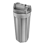
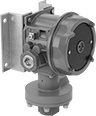
Hazardous Location Pressure Switches
Style A | Style B |
Built with an explosion-proof enclosure to meet NEMA 7 and 9 standards for hazardous locations, these switches were tested and verified by UL and CSA for use where explosive liquids, dust, and gas are present. When they reach the set pressure, they power equipment, signal controls, or trigger alarms. They’re single pole, double throw (SPDT) and can be installed to turn one circuit from off to on (normally open) or from on to off (normally closed). In addition to being UL listed and CSA certified, these switches are CE marked, so they also meet European safety standards.
All switches are IP and NEMA rated for use outdoors and protection from some corrosion, dust, and spraying water.
Wire Lead Connection
Style A | Style B |
IP67 Enclosure Rating and NEMA 4X Enclosure Rating—IP67 and NEMA 4X rated switches seal out water from temporary submersion and have increased protection against corrosion, similar to 304 stainless steel.
Style | Pressure Set Point Range, psi | Approx. Difference Between Set Point and Reset Point, psi | Max. Continuous Pressure, psi | Max. Short-Term Pressure, psi | Accuracy | Max. Switching Current @ Voltage | Process Temp. Range, ° F | Connection Material | For Use With | Enclosure Rating | Hazardous Location Rating | Certification | Each | ||||||||||||||||||||||||||||||||||||||||||||||||||||||||||||||||||||||||||||||||||||||
|---|---|---|---|---|---|---|---|---|---|---|---|---|---|---|---|---|---|---|---|---|---|---|---|---|---|---|---|---|---|---|---|---|---|---|---|---|---|---|---|---|---|---|---|---|---|---|---|---|---|---|---|---|---|---|---|---|---|---|---|---|---|---|---|---|---|---|---|---|---|---|---|---|---|---|---|---|---|---|---|---|---|---|---|---|---|---|---|---|---|---|---|---|---|---|---|---|---|---|---|
1/4 Threaded NPT Male Pipe | |||||||||||||||||||||||||||||||||||||||||||||||||||||||||||||||||||||||||||||||||||||||||||||||||||
Internal Adjustment | |||||||||||||||||||||||||||||||||||||||||||||||||||||||||||||||||||||||||||||||||||||||||||||||||||
| A | 8 to 60 | 5 | 60 | 1,000 | ±5% | 5 amp @ 125V AC 5 amp @ 250V AC | -40 to 190 | 316 Stainless Steel | Air, Diesel Fuel, Gasoline, Hydraulic Fluid, Natural Gas, Water | IP67, NEMA 4X, NEMA 7, NEMA 9 | NEC Class I Divisions 1, 2 Groups A, B, C, D NEC Class II Divisions 1, 2 Groups E, F, G | CE Marked, CSA Certified, UL Listed | 46985K71 | 0000000 | |||||||||||||||||||||||||||||||||||||||||||||||||||||||||||||||||||||||||||||||||||||
| A | 10 to 100 | 9 | 100 | 1,000 | ±5% | 5 amp @ 125V AC 5 amp @ 250V AC | -40 to 190 | 316 Stainless Steel | Air, Diesel Fuel, Gasoline, Hydraulic Fluid, Natural Gas, Water | IP67, NEMA 4X, NEMA 7, NEMA 9 | NEC Class I Divisions 1, 2 Groups A, B, C, D NEC Class II Divisions 1, 2 Groups E, F, G | CE Marked, CSA Certified, UL Listed | 46985K72 | 000000 | |||||||||||||||||||||||||||||||||||||||||||||||||||||||||||||||||||||||||||||||||||||
| A | 20 to 200 | 16 | 200 | 1,000 | ±2% | 5 amp @ 125V AC 5 amp @ 250V AC | -40 to 190 | 316 Stainless Steel | Air, Diesel Fuel, Gasoline, Hydraulic Fluid, Natural Gas, Water | IP67, NEMA 4X, NEMA 7, NEMA 9 | NEC Class I Divisions 1, 2 Groups A, B, C, D NEC Class II Divisions 1, 2 Groups E, F, G | CE Marked, CSA Certified, UL Listed | 46985K73 | 000000 | |||||||||||||||||||||||||||||||||||||||||||||||||||||||||||||||||||||||||||||||||||||
| A | 50 to 500 | 60 | 500 | 5,000 | ±2% | 5 amp @ 125V AC 5 amp @ 250V AC | -40 to 190 | 316 Stainless Steel | Air, Diesel Fuel, Gasoline, Hydraulic Fluid, Natural Gas, Water | IP67, NEMA 4X, NEMA 7, NEMA 9 | NEC Class I Divisions 1, 2 Groups A, B, C, D NEC Class II Divisions 1, 2 Groups E, F, G | CE Marked, CSA Certified, UL Listed | 46985K74 | 000000 | |||||||||||||||||||||||||||||||||||||||||||||||||||||||||||||||||||||||||||||||||||||
| A | 100 to 1,000 | 87 | 1,000 | 5,000 | ±2% | 5 amp @ 125V AC 5 amp @ 250V AC | -40 to 190 | 316 Stainless Steel | Air, Diesel Fuel, Gasoline, Hydraulic Fluid, Natural Gas, Water | IP67, NEMA 4X, NEMA 7, NEMA 9 | NEC Class I Divisions 1, 2 Groups A, B, C, D NEC Class II Divisions 1, 2 Groups E, F, G | CE Marked, CSA Certified, UL Listed | 46985K75 | 000000 | |||||||||||||||||||||||||||||||||||||||||||||||||||||||||||||||||||||||||||||||||||||
| A | 200 to 2,000 | 165 | 2,000 | 5,000 | ±2% | 5 amp @ 125V AC 5 amp @ 250V AC | -40 to 190 | 316 Stainless Steel | Air, Diesel Fuel, Gasoline, Hydraulic Fluid, Natural Gas, Water | IP67, NEMA 4X, NEMA 7, NEMA 9 | NEC Class I Divisions 1, 2 Groups A, B, C, D NEC Class II Divisions 1, 2 Groups E, F, G | CE Marked, CSA Certified, UL Listed | 46985K76 | 000000 | |||||||||||||||||||||||||||||||||||||||||||||||||||||||||||||||||||||||||||||||||||||
1/2 Threaded NPT Female Pipe | |||||||||||||||||||||||||||||||||||||||||||||||||||||||||||||||||||||||||||||||||||||||||||||||||||
Internal Adjustment | |||||||||||||||||||||||||||||||||||||||||||||||||||||||||||||||||||||||||||||||||||||||||||||||||||
| B | 6 to 30 | 2 | 30 | 1,000 | ±1% | 5 amp @ 125V AC 5 amp @ 250V AC | 0 to 200 | 316 Stainless Steel | Air, Diesel Fuel, Gasoline, Hydraulic Fluid, Natural Gas, Water | IP66, NEMA 4, NEMA 7, NEMA 9 | NEC Class I Divisions 1, 2 Groups A, B, C, D NEC Class II Divisions 1, 2 Groups E, F, G | CE Marked, CSA Certified, UL Listed | 46985K61 | 000000 | |||||||||||||||||||||||||||||||||||||||||||||||||||||||||||||||||||||||||||||||||||||
| B | 12 to 60 | 2 | 60 | 1,000 | ±1% | 5 amp @ 125V AC 5 amp @ 250V AC | 0 to 200 | 316 Stainless Steel | Air, Diesel Fuel, Gasoline, Hydraulic Fluid, Natural Gas, Water | IP66, NEMA 4, NEMA 7, NEMA 9 | NEC Class I Divisions 1, 2 Groups A, B, C, D NEC Class II Divisions 1, 2 Groups E, F, G | CE Marked, CSA Certified, UL Listed | 46985K62 | 000000 | |||||||||||||||||||||||||||||||||||||||||||||||||||||||||||||||||||||||||||||||||||||
| B | 20 to 100 | 3.5 | 100 | 1,000 | ±1% | 5 amp @ 125V AC 5 amp @ 250V AC | 0 to 200 | 316 Stainless Steel | Air, Diesel Fuel, Gasoline, Hydraulic Fluid, Natural Gas, Water | IP66, NEMA 4, NEMA 7, NEMA 9 | NEC Class I Divisions 1, 2 Groups A, B, C, D NEC Class II Divisions 1, 2 Groups E, F, G | CE Marked, CSA Certified, UL Listed | 46985K63 | 000000 | |||||||||||||||||||||||||||||||||||||||||||||||||||||||||||||||||||||||||||||||||||||
| B | 40 to 200 | 6.5 | 200 | 1,000 | ±1% | 5 amp @ 125V AC 5 amp @ 250V AC | 0 to 200 | 316 Stainless Steel | Air, Diesel Fuel, Gasoline, Hydraulic Fluid, Natural Gas, Water | IP66, NEMA 4, NEMA 7, NEMA 9 | NEC Class I Divisions 1, 2 Groups A, B, C, D NEC Class II Divisions 1, 2 Groups E, F, G | CE Marked, CSA Certified, UL Listed | 46985K64 | 000000 | |||||||||||||||||||||||||||||||||||||||||||||||||||||||||||||||||||||||||||||||||||||
| B | 80 to 400 | 11 | 400 | 1,600 | ±1% | 5 amp @ 125V AC 5 amp @ 250V AC | 0 to 200 | 316 Stainless Steel | Air, Diesel Fuel, Gasoline, Hydraulic Fluid, Natural Gas, Water | IP66, NEMA 4, NEMA 7, NEMA 9 | NEC Class I Divisions 1, 2 Groups A, B, C, D NEC Class II Divisions 1, 2 Groups E, F, G | CE Marked, CSA Certified, UL Listed | 46985K65 | 000000 | |||||||||||||||||||||||||||||||||||||||||||||||||||||||||||||||||||||||||||||||||||||
Differential Pressure Switches with Dial Indicator for Liquids
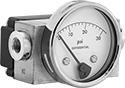 |
To check the difference in pressure between two points, these switches have a dial indicator that shows differential pressure in real time. The dial indicator operates independently of the switch. You’ll sometimes see these switches used to indicate a filter is clogged in a pump or cooling system. When the differential pressure reaches your setpoint, they turn equipment on and off, activate automated controls, or signal alarms. They are single pole, double throw (SPDT) and can be installed to turn one circuit from off to on or from on to off.
Rated NEMA 4X, these switches protect against dirt, washdown, and corrosion. They are also rated IP65 for protection from dust and rinsing. All are CSA certified, so they meet Canadian safety standards.
Pressure Set Point | Approx. Difference Between Set Point and Reset Point | Max. Input Pressure, psi | Accuracy | Max. Switching Current @ Voltage | Process Temp. Range, ° F | Connection Material | For Use With | Certification | Enclosure Rating | Hazardous Location Rating | Each | ||||||||||||||||||||||||||||||||||||||||||||||||||||||||||||||||||||||||||||||||||||||||
|---|---|---|---|---|---|---|---|---|---|---|---|---|---|---|---|---|---|---|---|---|---|---|---|---|---|---|---|---|---|---|---|---|---|---|---|---|---|---|---|---|---|---|---|---|---|---|---|---|---|---|---|---|---|---|---|---|---|---|---|---|---|---|---|---|---|---|---|---|---|---|---|---|---|---|---|---|---|---|---|---|---|---|---|---|---|---|---|---|---|---|---|---|---|---|---|---|---|---|---|
Screw-Terminal Wire Connection | |||||||||||||||||||||||||||||||||||||||||||||||||||||||||||||||||||||||||||||||||||||||||||||||||||
1/4 NPT Female Pipe Connection | |||||||||||||||||||||||||||||||||||||||||||||||||||||||||||||||||||||||||||||||||||||||||||||||||||
| 0 in. H₂O to 25 in. H₂O | 5 in. H₂O | 1,500 | ±2% | 250 mA @ 120V AC | -20 to 175 | Brass | Cleaning Solutions, Diesel Fuel, Gasoline, Hydraulic Fluid, Oil, Water | CSA Certified | IP65, NEMA 4X | NEC Class I Division 2 Groups A, B, C, D; NEC Class II Division 2 Groups F, G | 4587N11 | 0000000 | |||||||||||||||||||||||||||||||||||||||||||||||||||||||||||||||||||||||||||||||||||||||
| 0 psi to 1 psi | 0.2 psi | 1,500 | ±2% | 250 mA @ 120V AC | -20 to 175 | Brass | Cleaning Solutions, Diesel Fuel, Gasoline, Hydraulic Fluid, Oil, Water | CSA Certified | IP65, NEMA 4X | NEC Class I Division 2 Groups A, B, C, D; NEC Class II Division 2 Groups F, G | 4587N12 | 000000 | |||||||||||||||||||||||||||||||||||||||||||||||||||||||||||||||||||||||||||||||||||||||
| 0 psi to 5 psi | 1 psi | 1,500 | ±2% | 250 mA @ 120V AC | -20 to 175 | Brass | Cleaning Solutions, Diesel Fuel, Gasoline, Hydraulic Fluid, Oil, Water | CSA Certified | IP65, NEMA 4X | NEC Class I Division 2 Groups A, B, C, D; NEC Class II Division 2 Groups F, G | 4587N13 | 000000 | |||||||||||||||||||||||||||||||||||||||||||||||||||||||||||||||||||||||||||||||||||||||
| 3 psi to 15 psi | 3 psi | 5,000 | ±2% | 250 mA @ 120V AC | -40 to 175 | Brass | Cleaning Solutions, Diesel Fuel, Gasoline, Hydraulic Fluid, Oil, Water | CSA Certified | IP65, NEMA 4X | NEC Class I Division 2 Groups A, B, C, D; NEC Class II Division 2 Groups F, G | 40945K81 | 000000 | |||||||||||||||||||||||||||||||||||||||||||||||||||||||||||||||||||||||||||||||||||||||
| 6 psi to 30 psi | 6 psi | 5,000 | ±2% | 250 mA @ 120V AC | -40 to 175 | Brass | Cleaning Solutions, Diesel Fuel, Gasoline, Hydraulic Fluid, Oil, Water | CSA Certified | IP65, NEMA 4X | NEC Class I Division 2 Groups A, B, C, D; NEC Class II Division 2 Groups F, G | 40945K82 | 000000 | |||||||||||||||||||||||||||||||||||||||||||||||||||||||||||||||||||||||||||||||||||||||
| 10 psi to 50 psi | 10 psi | 5,000 | ±2% | 250 mA @ 120V AC | -40 to 175 | Brass | Cleaning Solutions, Diesel Fuel, Gasoline, Hydraulic Fluid, Oil, Water | CSA Certified | IP65, NEMA 4X | NEC Class I Division 2 Groups A, B, C, D; NEC Class II Division 2 Groups F, G | 40945K83 | 000000 | |||||||||||||||||||||||||||||||||||||||||||||||||||||||||||||||||||||||||||||||||||||||
Hazardous Location Differential Pressure Switches for Air
 |
With an explosion-proof enclosure that meets NEMA 7 and 9 standards for hazardous locations, these switches were tested and verified by UL for use where explosive gas or dust may be present. Often used with ovens, dryers, and HVAC systems, they can indicate a filter is clogged or help maintain a certain air pressure. These switches turn equipment on and off, activate automated controls, or signal alarms when the differential pressure reaches your setpoint. They are single pole, double throw (SPDT) and can be installed to turn one circuit from off to on or from on to off.
In addition to being UL listed, these switches are CE marked and FM approved, so they also meet European safety standards. They also are IP and NEMA rated for use outdoors and protect against dust and splashing water.
When measuring pressure in ductwork, pair them with a static pressure probe.
Pressure Set Point Range | Approx. Difference Between Set Point and Reset Point | Max. Input Pressure | Accuracy | Max. Switching Current @ Voltage | Process Temp. Range, ° F | Connection Material | For Use With | Enclosure Rating | Hazardous Location Rating | Each | |||||||||||||||||||||||||||||||||||||||||||||||||||||||||||||||||||||||||||||||||||||||||
|---|---|---|---|---|---|---|---|---|---|---|---|---|---|---|---|---|---|---|---|---|---|---|---|---|---|---|---|---|---|---|---|---|---|---|---|---|---|---|---|---|---|---|---|---|---|---|---|---|---|---|---|---|---|---|---|---|---|---|---|---|---|---|---|---|---|---|---|---|---|---|---|---|---|---|---|---|---|---|---|---|---|---|---|---|---|---|---|---|---|---|---|---|---|---|---|---|---|---|---|
Screw-Terminal Wire Connection | |||||||||||||||||||||||||||||||||||||||||||||||||||||||||||||||||||||||||||||||||||||||||||||||||||
1/8 NPT Female Pipe Connection | |||||||||||||||||||||||||||||||||||||||||||||||||||||||||||||||||||||||||||||||||||||||||||||||||||
| 0.07 in. H₂O to 0.15 in. H₂O | 0.13 in. H₂O | 45 in. H₂O | ±2% | 15 amp @ 125V AC 15 amp @ 250V AC 15 amp @ 480V AC | -40 to 140 | Aluminum | Air | IP54, NEMA 3, NEMA 7, NEMA 9 | NEC Class I Divisions 1, 2 Groups C, D; NEC Class II Divisions 1, 2 Groups E, F, G | 5114N11 | 0000000 | ||||||||||||||||||||||||||||||||||||||||||||||||||||||||||||||||||||||||||||||||||||||||
| 0.15 in. H₂O to 0.5 in. H₂O | 0.05 in. H₂O | 45 in. H₂O | ±2% | 15 amp @ 125V AC 15 amp @ 250V AC 15 amp @ 480V AC | -40 to 140 | Aluminum | Air | IP54, NEMA 3, NEMA 7, NEMA 9 | NEC Class I Divisions 1, 2 Groups C, D; NEC Class II Divisions 1, 2 Groups E, F, G | 5114N12 | 000000 | ||||||||||||||||||||||||||||||||||||||||||||||||||||||||||||||||||||||||||||||||||||||||
| 0.4 in. H₂O to 1.6 in. H₂O | 0.18 in. H₂O | 45 in. H₂O | ±2% | 15 amp @ 125V AC 15 amp @ 250V AC 15 amp @ 480V AC | -40 to 140 | Aluminum | Air | IP54, NEMA 3, NEMA 7, NEMA 9 | NEC Class I Divisions 1, 2 Groups C, D; NEC Class II Divisions 1, 2 Groups E, F, G | 5114N13 | 000000 | ||||||||||||||||||||||||||||||||||||||||||||||||||||||||||||||||||||||||||||||||||||||||
| 1.4 in. H₂O to 5.5 in. H₂O | 0.35 in. H₂O | 45 in. H₂O | ±2% | 15 amp @ 125V AC 15 amp @ 250V AC 15 amp @ 480V AC | -40 to 140 | Aluminum | Air | IP54, NEMA 3, NEMA 7, NEMA 9 | NEC Class I Divisions 1, 2 Groups C, D; NEC Class II Divisions 1, 2 Groups E, F, G | 5114N14 | 000000 | ||||||||||||||||||||||||||||||||||||||||||||||||||||||||||||||||||||||||||||||||||||||||
| 3 in. H₂O to 11 in. H₂O | 0.45 in. H₂O | 45 in. H₂O | ±2% | 15 amp @ 125V AC 15 amp @ 250V AC 15 amp @ 480V AC | -40 to 140 | Aluminum | Air | IP54, NEMA 3, NEMA 7, NEMA 9 | NEC Class I Divisions 1, 2 Groups C, D; NEC Class II Divisions 1, 2 Groups E, F, G | 5114N15 | 000000 | ||||||||||||||||||||||||||||||||||||||||||||||||||||||||||||||||||||||||||||||||||||||||
| 4 in. H₂O to 20 in. H₂O | 0.5 in. H₂O | 45 in. H₂O | ±2% | 15 amp @ 125V AC 15 amp @ 250V AC 15 amp @ 480V AC | -40 to 140 | Aluminum | Air | IP54, NEMA 3, NEMA 7, NEMA 9 | NEC Class I Divisions 1, 2 Groups C, D; NEC Class II Divisions 1, 2 Groups E, F, G | 5114N16 | 000000 | ||||||||||||||||||||||||||||||||||||||||||||||||||||||||||||||||||||||||||||||||||||||||
| 0.5 psi to 2 psi | 0.3 psi | 35 psi | ±2% | 15 amp @ 125V AC 15 amp @ 250V AC 15 amp @ 480V AC | -40 to 140 | Aluminum | Air | IP54, NEMA 3, NEMA 7, NEMA 9 | NEC Class I Divisions 1, 2 Groups C, D; NEC Class II Divisions 1, 2 Groups E, F, G | 5114N17 | 000000 | ||||||||||||||||||||||||||||||||||||||||||||||||||||||||||||||||||||||||||||||||||||||||
| 1.5 psi to 8 psi | 1 psi | 35 psi | ±2% | 15 amp @ 125V AC 15 amp @ 250V AC 15 amp @ 480V AC | 0 to 140 | Aluminum | Air | IP54, NEMA 3, NEMA 7, NEMA 9 | NEC Class I Divisions 1, 2 Groups C, D; NEC Class II Divisions 1, 2 Groups E, F, G | 5114N18 | 000000 | ||||||||||||||||||||||||||||||||||||||||||||||||||||||||||||||||||||||||||||||||||||||||
| 3 psi to 15 psi | 0.9 psi | 35 psi | ±2% | 15 amp @ 125V AC 15 amp @ 250V AC 15 amp @ 480V AC | 0 to 140 | Aluminum | Air | IP54, NEMA 3, NEMA 7, NEMA 9 | NEC Class I Divisions 1, 2 Groups C, D; NEC Class II Divisions 1, 2 Groups E, F, G | 5114N19 | 000000 | ||||||||||||||||||||||||||||||||||||||||||||||||||||||||||||||||||||||||||||||||||||||||
| 4 psi to 25 psi | 0.7 psi | 35 psi | ±2% | 15 amp @ 125V AC 15 amp @ 250V AC 15 amp @ 480V AC | 0 to 140 | Aluminum | Air | IP54, NEMA 3, NEMA 7, NEMA 9 | NEC Class I Divisions 1, 2 Groups C, D; NEC Class II Divisions 1, 2 Groups E, F, G | 5114N21 | 000000 | ||||||||||||||||||||||||||||||||||||||||||||||||||||||||||||||||||||||||||||||||||||||||
| 15 psi to 50 psi | 1.25 psi | 70 psi | ±2% | 15 amp @ 125V AC 15 amp @ 250V AC 15 amp @ 480V AC | 0 to 140 | Aluminum | Air | IP54, NEMA 3, NEMA 7, NEMA 9 | NEC Class I Divisions 1, 2 Groups C, D; NEC Class II Divisions 1, 2 Groups E, F, G | 5114N22 | 000000 | ||||||||||||||||||||||||||||||||||||||||||||||||||||||||||||||||||||||||||||||||||||||||
Hazardous Location Differential Pressure Switches for Liquids
 |
Tested and verified by UL and C-UL for use where explosive dust or gas are present, these switches have an explosion-proof enclosure that meets NEMA 7 and 9 standards for hazardous locations. They are often used to indicate a filter is clogged in a pump or cooling system. When the differential pressure reaches your setpoint, these switches can turn equipment on and off, activate automated controls, or signal alarms. They are single pole, double throw (SPDT) and can be installed to turn one circuit from off to on or from on to off.
In addition to being UL and C-UL listed, these switches are CE marked, so they also meet European safety standards. All switches are IP and NEMA rated for use outdoors and to protect against some corrosion, dust, and washdowns.
Pressure Set Point Range | Approx. Difference Between Set Point and Reset Point | Max. Input Pressure, psi | Accuracy | Max. Switching Current @ Voltage | Process Temp. Range, ° F | Connection Material | For Use With | Enclosure Rating | Hazardous Location Rating | Each | |||||||||||||||||||||||||||||||||||||||||||||||||||||||||||||||||||||||||||||||||||||||||
|---|---|---|---|---|---|---|---|---|---|---|---|---|---|---|---|---|---|---|---|---|---|---|---|---|---|---|---|---|---|---|---|---|---|---|---|---|---|---|---|---|---|---|---|---|---|---|---|---|---|---|---|---|---|---|---|---|---|---|---|---|---|---|---|---|---|---|---|---|---|---|---|---|---|---|---|---|---|---|---|---|---|---|---|---|---|---|---|---|---|---|---|---|---|---|---|---|---|---|---|
Screw-Terminal Wire Connection | |||||||||||||||||||||||||||||||||||||||||||||||||||||||||||||||||||||||||||||||||||||||||||||||||||
1/4 NPT Female Pipe Connection | |||||||||||||||||||||||||||||||||||||||||||||||||||||||||||||||||||||||||||||||||||||||||||||||||||
| 5 in. H₂O to 80 in. H₂O | 2.5 in. H₂O | 225 | ±0.5% | 15 amp @ 125V AC 15 amp @ 250V AC 15 amp @ 480V AC 2 amp @ 30V DC 1 amp @ 48V DC 500 mA @ 125V DC | -10 to 200 | Aluminum | Diesel Fuel, Gasoline, Petroleum-Based Hydraulic Oil, Water | NEMA 4X, NEMA 7, NEMA 9, IP66 | NEC Class I Divisions 1, 2 Groups B, C, D; NEC Class II Divisions 1, 2 Groups E, F, G | 5214N11 | 0000000 | ||||||||||||||||||||||||||||||||||||||||||||||||||||||||||||||||||||||||||||||||||||||||
| 2 psi to 20 psi | 0.2 psi | 225 | ±0.5% | 15 amp @ 125V AC 15 amp @ 250V AC 15 amp @ 480V AC 2 amp @ 30V DC 1 amp @ 48V DC 500 mA @ 125V DC | -10 to 200 | Aluminum | Diesel Fuel, Gasoline, Petroleum-Based Hydraulic Oil, Water | NEMA 4X, NEMA 7, NEMA 9, IP66 | NEC Class I Divisions 1, 2 Groups B, C, D; NEC Class II Divisions 1, 2 Groups E, F, G | 5214N12 | 000000 | ||||||||||||||||||||||||||||||||||||||||||||||||||||||||||||||||||||||||||||||||||||||||
| 3 psi to 30 psi | 0.25 psi | 225 | ±0.5% | 15 amp @ 125V AC 15 amp @ 250V AC 15 amp @ 480V AC 2 amp @ 30V DC 1 amp @ 48V DC 500 mA @ 125V DC | -10 to 200 | Aluminum | Diesel Fuel, Gasoline, Petroleum-Based Hydraulic Oil, Water | NEMA 4X, NEMA 7, NEMA 9, IP66 | NEC Class I Divisions 1, 2 Groups B, C, D; NEC Class II Divisions 1, 2 Groups E, F, G | 5214N13 | 000000 | ||||||||||||||||||||||||||||||||||||||||||||||||||||||||||||||||||||||||||||||||||||||||
| 10 psi to 100 psi | 0.6 psi | 225 | ±0.5% | 15 amp @ 125V AC 15 amp @ 250V AC 15 amp @ 480V AC 2 amp @ 30V DC 1 amp @ 48V DC 500 mA @ 125V DC | -10 to 200 | Aluminum | Diesel Fuel, Gasoline, Petroleum-Based Hydraulic Oil, Water | NEMA 4X, NEMA 7, NEMA 9, IP66 | NEC Class I Divisions 1, 2 Groups B, C, D; NEC Class II Divisions 1, 2 Groups E, F, G | 5214N14 | 000000 | ||||||||||||||||||||||||||||||||||||||||||||||||||||||||||||||||||||||||||||||||||||||||
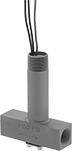
Fixed-Set-Point Hazardous-Location Flow Switches
 |
Safe to use where flammable gases and combustible dust may be present, these switches activate or deactivate when your flow reaches a factory-set level. All are UL listed for hazardous environments. Because their set point is fixed, they’re ready to go, making them easy to install. They actuate when your flowing liquid or gas pushes their paddle into a set position. These switches are single pole, double throw (SPDT) and can turn one device from off to on (normally open) or from on to off (normally closed). They must be mounted horizontally to function accurately.
These switches are calibrated with water and air. They can also be used with other liquids and gases but may not measure accurately if their viscosity is significantly different.
Set Point | Conduit | ||||||||||||||||||||||||||||||||||||||||||||||||||||||||||||||||||||||||||||||||||||||||||||||||||
|---|---|---|---|---|---|---|---|---|---|---|---|---|---|---|---|---|---|---|---|---|---|---|---|---|---|---|---|---|---|---|---|---|---|---|---|---|---|---|---|---|---|---|---|---|---|---|---|---|---|---|---|---|---|---|---|---|---|---|---|---|---|---|---|---|---|---|---|---|---|---|---|---|---|---|---|---|---|---|---|---|---|---|---|---|---|---|---|---|---|---|---|---|---|---|---|---|---|---|---|
Pipe Connections | For Liquids, gpm | For Gas, scfm | Max. Pressure @ Temp. | Temp. Range, ° F | Voltage, V AC | Max. Switching Current @ Voltage | Trade Size | Thread Type | Gender | End-to-End Lg. | Enclosure Rating | Certification | Each | ||||||||||||||||||||||||||||||||||||||||||||||||||||||||||||||||||||||||||||||||||||||
304 Stainless Steel Body with Threaded 304 Stainless Steel Fittings | |||||||||||||||||||||||||||||||||||||||||||||||||||||||||||||||||||||||||||||||||||||||||||||||||||
| 1/2 NPT Female | 1.5 | 6.5 | 2,000 psi @ 70° F | -4 to 220 | 120/240 | 5 amp @ 120V AC | 3/4 | NPT | Male | 2 1/4" | NEMA 4 | UL Listed CE Marked | 47565K61 | 0000000 | |||||||||||||||||||||||||||||||||||||||||||||||||||||||||||||||||||||||||||||||||||||
| 3/4 NPT Female | 2 | 10 | 2,000 psi @ 70° F | -4 to 220 | 120/240 | 5 amp @ 120V AC | 3/4 | NPT | Male | 2 5/8" | NEMA 4 | UL Listed CE Marked | 47565K62 | 000000 | |||||||||||||||||||||||||||||||||||||||||||||||||||||||||||||||||||||||||||||||||||||
| 1 NPT Female | 3 | 14 | 2,000 psi @ 70° F | -4 to 220 | 120/240 | 5 amp @ 120V AC | 3/4 | NPT | Male | 3" | NEMA 4 | UL Listed CE Marked | 47565K63 | 000000 | |||||||||||||||||||||||||||||||||||||||||||||||||||||||||||||||||||||||||||||||||||||
| 2 NPT Female | 10 | 43 | 2,000 psi @ 70° F | -4 to 220 | 120/240 | 5 amp @ 120V AC | 3/4 | NPT | Male | 4 3/4" | NEMA 4 | UL Listed CE Marked | 47565K66 | 00000000 | |||||||||||||||||||||||||||||||||||||||||||||||||||||||||||||||||||||||||||||||||||||
Brass Body with Threaded Brass Fittings | |||||||||||||||||||||||||||||||||||||||||||||||||||||||||||||||||||||||||||||||||||||||||||||||||||
| 1/2 NPT Female | 1.5 | 6.5 | 250 psi @ 70° F | -4 to 220 | 120/240 | 5 amp @ 120V AC | 3/4 | NPT | Male | 2 1/4" | NEMA 4 | UL Listed CE Marked | 47565K31 | 000000 | |||||||||||||||||||||||||||||||||||||||||||||||||||||||||||||||||||||||||||||||||||||
| 3/4 NPT Female | 2 | 10 | 250 psi @ 70° F | -4 to 220 | 120/240 | 5 amp @ 120V AC | 3/4 | NPT | Male | 2 3/8" | NEMA 4 | UL Listed CE Marked | 47565K32 | 000000 | |||||||||||||||||||||||||||||||||||||||||||||||||||||||||||||||||||||||||||||||||||||
| 1 NPT Female | 3 | 14 | 250 psi @ 70° F | -4 to 220 | 120/240 | 5 amp @ 120V AC | 3/4 | NPT | Male | 2 1/2" | NEMA 4 | UL Listed CE Marked | 47565K33 | 000000 | |||||||||||||||||||||||||||||||||||||||||||||||||||||||||||||||||||||||||||||||||||||
| 1 1/4 NPT Female | 4 | 21 | 250 psi @ 70° F | -4 to 220 | 120/240 | 5 amp @ 120V AC | 3/4 | NPT | Male | 2 5/8" | NEMA 4 | UL Listed CE Marked | 47565K34 | 000000 | |||||||||||||||||||||||||||||||||||||||||||||||||||||||||||||||||||||||||||||||||||||
| 1 1/2 NPT Female | 6 | 33 | 250 psi @ 70° F | -4 to 220 | 120/240 | 5 amp @ 120V AC | 3/4 | NPT | Male | 2 7/8" | NEMA 4 | UL Listed CE Marked | 47565K35 | 000000 | |||||||||||||||||||||||||||||||||||||||||||||||||||||||||||||||||||||||||||||||||||||
| 2 NPT Female | 10 | 43 | 250 psi @ 70° F | -4 to 220 | 120/240 | 5 amp @ 120V AC | 3/4 | NPT | Male | 3" | NEMA 4 | UL Listed CE Marked | 47565K36 | 000000 | |||||||||||||||||||||||||||||||||||||||||||||||||||||||||||||||||||||||||||||||||||||
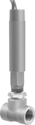
Hazardous-Location Insertion-Mount Flow Switches
 |
Safely activate and deactivate equipment in environments with flammable gases and combustible dust when your flow rate reaches a set point. They are UL listed and CSA certified for use in hazardous locations. These switches save you from disassembling your pipeline because you insert them into pipe tees or pipe outlets instead of mounting them inline. They actuate when your system’s liquid pushes the paddle into a set position. To change your set point, the paddle has multiple layers that you can remove. For the lowest set point, use the largest paddle that will fit your pipe. To increase your set point, loosen the locking washers and remove paddles. You can trim the paddles to fine-tune your set point. The smaller the paddle, the higher the setpoint.
They should be mounted vertically into a horizontal pipeline, so liquid pushes the paddle.
These switches are calibrated with water and air. They can also be used with other liquids and gases but may not measure accurately if their viscosity is significantly different.
SPDT—SPDT (singe pole, double throw) switches can turn one device from off to on (normally open) or from on to off (normally closed).
DPDT—DPDT (double pole, double throw) switches can either turn two devices from off to on (normally open) or on to off (normally closed).
Flow Set Point Range | Max. Flow Rate | Conduit | |||||||||||||||||||||||||||||||||||||||||||||||||||||||||||||||||||||||||||||||||||||||||||||||||
|---|---|---|---|---|---|---|---|---|---|---|---|---|---|---|---|---|---|---|---|---|---|---|---|---|---|---|---|---|---|---|---|---|---|---|---|---|---|---|---|---|---|---|---|---|---|---|---|---|---|---|---|---|---|---|---|---|---|---|---|---|---|---|---|---|---|---|---|---|---|---|---|---|---|---|---|---|---|---|---|---|---|---|---|---|---|---|---|---|---|---|---|---|---|---|---|---|---|---|---|
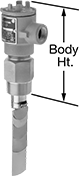
Pipe Size | Thread Type | Gender | For Pipe Size | For Water and Oil | For Air and Inert Gas | For Water and Oil | For Air and Inert Gas | Max. Pressure @ Temp. | Temp. Range, ° F | Max. Switching Current @ Voltage | Trade Size | Thread Type | Gender | Body Ht. | Each | ||||||||||||||||||||||||||||||||||||||||||||||||||||||||||||||||||||||||||||||||||||
SPDT | |||||||||||||||||||||||||||||||||||||||||||||||||||||||||||||||||||||||||||||||||||||||||||||||||||
Brass Body | |||||||||||||||||||||||||||||||||||||||||||||||||||||||||||||||||||||||||||||||||||||||||||||||||||
| 1 1/2 | NPT | Male | 1 1/2 2 4 12 20 | 3 gpm to 7 gpm 4 gpm to 15 gpm 12 gpm to 95 gpm 140 gpm to 900 gpm 400 gpm to 2,400 gpm | 17 scfm to 32 scfm 13 scfm to 65 scfm 50 scfm to 400 scfm 800 scfm to 3,450 scfm 2,850 scfm to 10,000 scfm | 55 gpm 97 gpm 391 gpm 3,525 gpm 9,792 gpm | Not Rated | 1,000 psi @ 70° F | -4 to 275 | 5 amp @ 125V AC 5 amp @ 250V AC | 3/4 | NPT | Female | 8" | 48005K53 | 0000000 | |||||||||||||||||||||||||||||||||||||||||||||||||||||||||||||||||||||||||||||||||||
316 Stainless Steel Body | |||||||||||||||||||||||||||||||||||||||||||||||||||||||||||||||||||||||||||||||||||||||||||||||||||
| 1 1/2 | NPT | Male | 1 1/2 2 4 12 20 | 3 gpm to 7 gpm 4 gpm to 15 gpm 12 gpm to 95 gpm 140 gpm to 900 gpm 400 gpm to 2,400 gpm | 17 scfm to 32 scfm 13 scfm to 65 scfm 50 scfm to 400 scfm 800 scfm to 3,450 scfm 2,850 scfm to 10,000 scfm | 55 gpm 97 gpm 391 gpm 3,525 gpm 9,792 gpm | Not Rated | 2,000 psi @ 70° F | -4 to 275 | 5 amp @ 125V AC 5 amp @ 250V AC | 3/4 | NPT | Female | 8" | 48005K55 | 00000000 | |||||||||||||||||||||||||||||||||||||||||||||||||||||||||||||||||||||||||||||||||||
DPDT | |||||||||||||||||||||||||||||||||||||||||||||||||||||||||||||||||||||||||||||||||||||||||||||||||||
Brass Body | |||||||||||||||||||||||||||||||||||||||||||||||||||||||||||||||||||||||||||||||||||||||||||||||||||
| 1 1/2 | NPT | Male | 1 1/2 2 4 12 20 | 3 gpm to 7 gpm 4 gpm to 15 gpm 12 gpm to 95 gpm 140 gpm to 900 gpm 400 gpm to 2,400 gpm | 17 scfm to 32 scfm 13 scfm to 65 scfm 50 scfm to 400 scfm 800 scfm to 3,450 scfm 2,850 scfm to 10,000 scfm | 55 gpm 97 gpm 391 gpm 3,525 gpm 9,792 gpm | Not Rated | 1,000 psi @ 70° F | -4 to 275 | 5 amp @ 125V AC 5 amp @ 250V AC | 3/4 | NPT | Female | 8" | 48005K54 | 000000 | |||||||||||||||||||||||||||||||||||||||||||||||||||||||||||||||||||||||||||||||||||
316 Stainless Steel Body | |||||||||||||||||||||||||||||||||||||||||||||||||||||||||||||||||||||||||||||||||||||||||||||||||||
| 1 1/2 | NPT | Male | 1 1/2 2 4 12 20 | 3 gpm to 7 gpm 4 gpm to 15 gpm 12 gpm to 95 gpm 140 gpm to 900 gpm 400 gpm to 2,400 gpm | 17 scfm to 32 scfm 13 scfm to 65 scfm 50 scfm to 400 scfm 800 scfm to 3,450 scfm 2,850 scfm to 10,000 scfm | 55 gpm 97 gpm 391 gpm 3,525 gpm 9,792 gpm | Not Rated | 2,000 psi @ 70° F | -4 to 275 | 5 amp @ 125V AC 5 amp @ 250V AC | 3/4 | NPT | Female | 8" | 48005K56 | 00000000 | |||||||||||||||||||||||||||||||||||||||||||||||||||||||||||||||||||||||||||||||||||
Hazardous-Location Flow Switches
 |
UL listed for use where flammable gases or combustible dusts may be present, these flow switches activate or deactivate equipment when your flow rate reaches a set point. Use the adjustment screw to select their set point. They actuate when your flowing liquid or gas pushes their paddle into a certain position determined by the set point. All are single pole, double throw (SPDT) and can either turn one device from off to on (normally open) or on to off (normally closed). Mount them horizontally. Rated NEMA 4, they also protect against weather and washdowns.
These flow switches are calibrated with water and air. You can use them with other liquids and gases, but they may not measure accurately if the viscosity is different from water or air.
Flow Set Point | Conduit | ||||||||||||||||||||||||||||||||||||||||||||||||||||||||||||||||||||||||||||||||||||||||||||||||||
|---|---|---|---|---|---|---|---|---|---|---|---|---|---|---|---|---|---|---|---|---|---|---|---|---|---|---|---|---|---|---|---|---|---|---|---|---|---|---|---|---|---|---|---|---|---|---|---|---|---|---|---|---|---|---|---|---|---|---|---|---|---|---|---|---|---|---|---|---|---|---|---|---|---|---|---|---|---|---|---|---|---|---|---|---|---|---|---|---|---|---|---|---|---|---|---|---|---|---|---|
Pipe Connections | For Liquids, gpm | For Gas, scfm | Max. Pressure @ Temp. | Temp. Range, ° F | Voltage, V AC | Max. Switching Current @ Voltage | Trade Size | Thread Type | Gender | End-to-End Lg. | Enclosure Rating | Certification | Each | ||||||||||||||||||||||||||||||||||||||||||||||||||||||||||||||||||||||||||||||||||||||
304 Stainless Steel Body with Threaded 304 Stainless Steel Fittings | |||||||||||||||||||||||||||||||||||||||||||||||||||||||||||||||||||||||||||||||||||||||||||||||||||
| 1/2 NPT Female | 0.04 to 0.75 | 0.18 to 2.7 | 1,450 psi @ 70° F | -4 to 220 | 120/240 | 5 amp @ 120V AC | 3/4 | NPT | Male | 3 5/8" | NEMA 4 | UL Listed CE Marked | 91445K24 | 0000000 | |||||||||||||||||||||||||||||||||||||||||||||||||||||||||||||||||||||||||||||||||||||
Brass Body with Threaded Brass Fittings | |||||||||||||||||||||||||||||||||||||||||||||||||||||||||||||||||||||||||||||||||||||||||||||||||||
| 1/2 NPT Female | 0.04 to 0.75 | 0.18 to 2.7 | 1,450 psi @ 70° F | -4 to 220 | 120/240 | 5 amp @ 120V AC | 3/4 | NPT | Male | 3 5/8" | NEMA 4 | UL Listed CE Marked | 91445K23 | 000000 | |||||||||||||||||||||||||||||||||||||||||||||||||||||||||||||||||||||||||||||||||||||
