


Installation Tips for Heat-Set Inserts
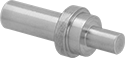
Attach these installation tips to a soldering iron. The tips transfer heat from the soldering iron to the insert, softening the surrounding plastic. When the plastic cools, it solidifies around the knurls and ridges on the insert to keep it secure and resistant to torque.
| For Thread Size | Tip Shank Dia. | Tip Connection Type | Each | |
| 1/4"-20, 1/4"-28, M6 | 1/4" | Plug | 000000000 | 000000 |
Extraction Tips for Heat-Set Inserts
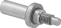
Extract heat-set inserts by attaching these tips to a soldering iron. The tips transfer heat from the soldering iron to the insert, softening the surrounding plastic to loosen the insert so it can be removed.
For Thread | ||||
|---|---|---|---|---|
| Size | Pitch, mm | Tip Shank Dia. | Each | |
| M6 | 1 | 1/4" | 000000000 | 000000 |
Heat-Set Insert Assortments for Plastic with Installation Tools
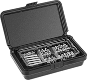
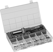
Keep a variety of heat-set insert sizes and installation tools on hand. The inserts install into a straight hole that has been drilled, printed, or molded into your plastic part. Heat inserts with a soldering iron (included in some assortments) to melt the plastic when installed. As the plastic cools, it solidifies around the knurls and ridges on the insert for excellent resistance to both torque and pull-out. Made from brass, they’re corrosion resistant, electrically conductive, and nonmagnetic.
Tapered inserts are easy to guide into a hole during installation. Use a drill bit to create a straight hole, then taper the top half.
| Includes | No. of Inserts Included | Material | Drill Bit Size | For Max. Hole Dia. | For Hole Taper Angle | Each | |
Metric—Tapered Body | |||||||
|---|---|---|---|---|---|---|---|
Standard | |||||||
| M2.5×0.45 mm Thread × 3.43 mm Installed Lg. (50 Each) M3×0.5 mm Thread × 3.81 mm Installed Lg. (50 Each) M4×0.7 mm Thread × 4.7 mm Installed Lg. (50 Each) M5×0.8 mm Thread × 6.73 mm Installed Lg. (25 Each) M6×1 mm Thread × 7.62 mm Installed Lg. (25 Each) Installation Tips | 200 | Brass | No. 24, No. 8, No. 2, N, S | 0.153", 0.199", 0.226", 0.303", 0.349" | 8° | 000000000 | 000000 |
| M2.5×0.45 mm Thread × 5.56 mm Installed Lg. (50 Each) M3×0.5 mm Thread × 6.35 mm Installed Lg. (50 Each) M4×0.7 mm Thread × 7.92 mm Installed Lg. (50 Each) M5×0.8 mm Thread × 11.13 mm Installed Lg. (25 Each) M6×1 mm Thread × 12.7 mm Installed Lg. (25 Each) Installation Tips | 200 | Brass | 9/64", No. 13, No. 5, J, O | 0.141", 0.185", 0.208", 0.278", 0.321" | 8° | 000000000 | 00000 |
| M2.5×0.45 mm Thread × 3.43 mm Installed Lg. (10 Each) M2.5×0.45 mm Thread × 5.56 mm Installed Lg. (10 Each) M3×0.5 mm Thread × 3.8 mm Installed Lg. (25 Each) M3×0.5 mm Thread × 6.35 mm Installed Lg. (25 each) M3.5×0.6 mm Thread × 3.81 mm Installed Lg. (25 Each) M3.5×0.6 mm Thread × 6.35 mm Installed Lg. (25 Each) M4×0.7 mm Thread × 4.7 mm Installed Lg. (25 Each) M4×0.7 mm Thread × 7.92 mm Installed Lg. (25 Each) M5×0.8 mm Thread × 6.73 mm Installed Lg. (25 Each) M5×0.8 mm Thread × 11.13 mm Installed Lg. (10 Each) M6×1 mm Thread × 7.62 mm Installed Lg. (10 Each) M6×1 mm Thread × 12.7 mm Installed Lg. (10 Each) Ceramic Insulation Tube Installation Tips Soldering Iron | 225 | Brass | 9/64", No. 24, No. 13, No. 8, No. 2, J, N, O, S | 0.141", 0.152", 0.185", 0.199", 0.221", 0.277", 0.302", 0.316", 0.348" | 8° | 000000000 | 000000 |