


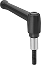
Heavy Duty Positioning Arms
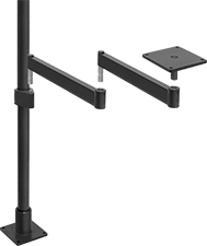 | 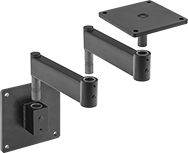 |
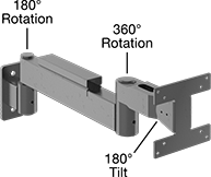
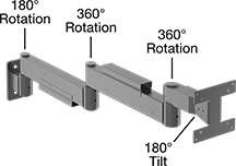
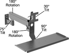
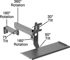
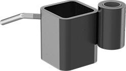
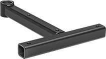
Arm Built with Floor- and Bench-Mount Pole Base, Pole, Pole-to-Pin Adapter, Two Rigid Connectors, and Pivoting Mounting Plate | Arm Built with Wall-Mount Pin Base, Two Rigid Connectors, and Pivoting Mounting Plate |
 |  |
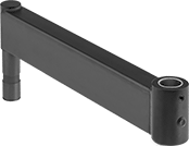
Complete Arms Screw On Style A | Complete Arms Screw On Style B |
 |  |
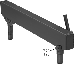
Complete Arms Screw On Style C | Complete Arms Screw On Style D |
 |  |
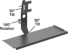
Complete Arms Screw On Style E | Complete Arms Screw On Style F |
 |  |
Complete Arms Screw On Style G | Complete Arms Screw On Style H |
| |
Screw On Style A | Screw On Style B |
| |
Screw On Style C | Screw On Style D |
| |
Screw On Style E | Screw On Style F |
| |
Screw On Style G | Screw On Style H |
Load Capacity, lb. | Base | Attaching End | ||||||||||||||||||
|---|---|---|---|---|---|---|---|---|---|---|---|---|---|---|---|---|---|---|---|---|
Style | Mounting Location | Max. Projection | Min. | Max. | Material | Color | Mounting Fasteners Included | Lg. | Wd. | No. of Mounting Holes | Mounting Hole Dia. | Plate Lg. | Plate Wd. | No. of Mounting Holes | Mounting Hole Dia. | Includes | Each | |||
Screw On | ||||||||||||||||||||
| A | Wall | 27" | — | 100 | Powder-Coated Steel | Black | No | 6" | 6" | 4 | 13/32" | 6" | 6" | 4 | 13/32" | Pivoting Mounting Plate, (2) Rigid Connectors, Pin Base | 5164T1 | 0000000 | ||
| A | Wall | 39" | — | 100 | Powder-Coated Steel | Black | No | 6" | 6" | 4 | 13/32" | 6" | 6" | 4 | 13/32" | Pivoting Mounting Plate, (2) Rigid Connectors, Pin Base | 5164T2 | 000000 | ||
| B | Wall | 7" | — | 25 | Powder-Coated Steel | Black | No | 4 1/2" | 2" | 2 | 13/32" | 4 1/2" | 4 1/2" | 8 | 3/16" | Flat-Panel Monitor Mounting Plate, Pin Base | 5164T31 | 000000 | ||
| C | Wall | 19" | — | 25 | Powder-Coated Steel | Black | No | 4 1/2" | 2" | 2 | 13/32" | 4 1/2" | 4 1/2" | 8 | 3/16" | Flat-Panel Monitor Mounting Plate, Rigid Connector, Cable Protector, Pin Base | 5164T32 | 000000 | ||
| D | Wall | 31" | — | 25 | Powder-Coated Steel | Black | No | 4 1/2" | 2" | 2 | 13/32" | 4 1/2" | 4 1/2" | 8 | 3/16" | Flat-Panel Monitor Mounting Plate, (2) Rigid Connectors, (2) Cable Protectors, Pin Base | 5164T33 | 000000 | ||
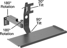
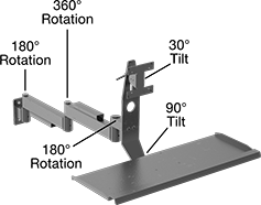
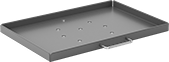
| E | Wall | 29" | — | 25 | Powder-Coated Steel | Black | No | 4 1/2" | 2" | 2 | 13/32" | 4 1/2" | 4 1/2" | 8 | 3/16" | Flat-Panel Monitor Mounting Plate, Keyboard Tray, Rigid Connector, Cable Protector, Pin Base | 5164T34 | 000000 | ||
| F | Wall | 41" | — | 25 | Powder-Coated Steel | Black | No | 4 1/2" | 2" | 2 | 13/32" | 4 1/2" | 4 1/2" | 8 | 3/16" | Flat-Panel Monitor Mounting Plate, Keyboard Tray, (2) Rigid Connectors, (2) Cable Protectors, Pin Base | 5164T35 | 000000 | ||
| G | Wall | 36" | 4 | 21 | Powder-Coated Steel | Black | No | 6" | 2 1/2" | 3 | 13/32" | 4 1/2" | 4 1/2" | 8 | 3/16" | Flat-Panel Monitor Mounting Plate, Keyboard Tray, Counterbalancing Connector, Cable Protector, Pin Base | 5164T38 | 000000 | ||
| H | Wall | 43" | 18 | 43 | Powder-Coated Steel | Black | No | 4 1/2" | 2" | 2 | 13/32" | 4 1/2" | 4 1/2" | 8 | 3/16" | Flat-Panel Monitor Mounting Plate, Keyboard Tray, Rigid Connector, Counterbalancing Connector, (2) Cable Protectors, Pin Base | 5164T37 | 000000 | ||
 |  |  |
Screw On Bench Mount | Wall- and T-Slot Rail-Mount Pin Base | Wall-Mount Pin Base |
For T-Slot Rail Ht. | Mounting | |||||||||||||||
|---|---|---|---|---|---|---|---|---|---|---|---|---|---|---|---|---|
Mounting Location | Single | Double, Quad | Lg. | Wd. | Ht. | For Pin Dia. | Max. Load Cap., lb. | Material | Color | Fasteners Included | No. of Holes | Hole Dia. | Each | |||
Screw On | ||||||||||||||||
| Bench | — | — | 6" | 6" | 3 1/8" | 7/8" | 100 | Powder-Coated Steel | Black | No | 4 | 13/32" | 5164T51 | 0000000 | ||
| T-Slotted Rail, Wall | 1 1/2", 30 mm, 40 mm, 45 mm | 3", 60 mm, 80 mm, 90 mm | 3" | 2" | 4 1/2" | 7/8" | 50 | Powder-Coated Steel | Black | No | 2 | 13/32" | 5164T942 | 00000 | ||
| T-Slotted Rail, Wall | 1 1/2", 30 mm, 40 mm, 45 mm | 3", 60 mm, 80 mm, 90 mm | 7 1/8" | 2 1/2" | 6" | 7/8" | 75 | Powder-Coated Steel | Black | No | 3 | 13/32" | 5164T943 | 000000 | ||
| Wall | — | — | 1 7/8" | 6" | 6" | 7/8" | 100 | Powder-Coated Steel | Black | No | 4 | 13/32" | 5164T52 | 000000 | ||
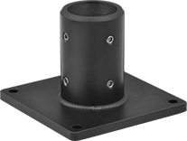 |  |
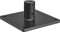
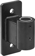
Floor- and Bench-Mount Pole Base | Screw On Wall Mount |
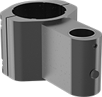 | 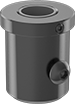 |  |
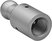
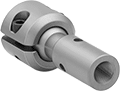
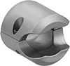
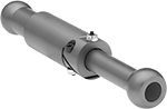
Clamp-On Adapter | Push-In Adapter | Clamp-On Adapter with Quick-Adjust Lever |
Lg. | Wd. | Ht. | For Pin Dia. | For Pole Dia. | Max. Load Cap., lb. | Material | Color | Each | |||
|---|---|---|---|---|---|---|---|---|---|---|---|
Clamp-On Adapter | |||||||||||
| 4 5/8" | 2 15/16" | 2 3/8" | 7/8" | 2" | 100 | Anodized Aluminum | Black | 5164T941 | 000000 | ||
| 4 5/8" | 2 15/16" | 2 5/8" | 7/8" | 1 1/2" | 100 | Anodized Aluminum | Black | 5164T41 | 000000 | ||
Push-In Adapter | |||||||||||
| 2 3/8" | 2" | 2 1/4" | 7/8" | 2" | 100 | Anodized Aluminum | Black | 5164T43 | 00000 | ||
Clamp-On Adapter with Quick-Adjust Lever | |||||||||||
| 7 13/16" | 3 1/8" | 3 7/16" | 7/8" | 2" | 100 | Powder-Coated Steel | Black | 5164T42 | 00000 | ||
 |
 |
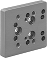
Mounting | ||||||||||||
|---|---|---|---|---|---|---|---|---|---|---|---|---|
Lg. | Wd. | Pin Dia. | Max. Load Cap., lb. | Material | Color | Fasteners Included | No. of Holes | Hole Dia. | Each | |||
| 6" | 6" | 7/8" | 100 | Powder-Coated Steel | Black | No | 4 | 13/32" | 5164T83 | 000000 | ||
 |
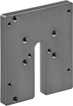
Mounting | |||||||||||||
|---|---|---|---|---|---|---|---|---|---|---|---|---|---|
Lg. | Wd. | Ht. | For Pin Dia. | Max. Load Cap., lb. | Material | Color | Fasteners Included | No. of Holes | Hole Dia. | Each | |||
| 3 7/8" | 3" | 3" | 7/8" | 100 | Powder-Coated Steel | Black | No | 4 | 9/32" | 5164T944 | 000000 | ||
 |
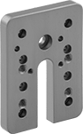
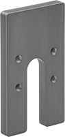
Mounting | Attaching End | |||||||||||||||
|---|---|---|---|---|---|---|---|---|---|---|---|---|---|---|---|---|
Lg. | Wd. | Ht. | For Pin Dia. | Max. Load Cap., lb. | Material | Color | Fasteners Included | No. of Holes | Hole Dia. | Pattern Compatibility | Plate Lg. | Plate Wd. | Each | |||
| 6 1/8" | 4 1/2" | 4 1/2" | 7/8" | 30 | Anodized Aluminum | Black | Yes | 8 | 7/32" | VESA 100 × 100 VESA 75 × 75 | 4 1/2" | 4 1/2" | 5164T955 | 0000000 | ||
 |
Mounting | Attaching End | |||||||||||||||
|---|---|---|---|---|---|---|---|---|---|---|---|---|---|---|---|---|
Lg. | Wd. | Ht. | For Pin Dia. | Max. Load Cap., lb. | Material | Color | Fasteners Included | No. of Holes | Hole Dia. | Pattern Compatibility | Plate Lg. | Plate Wd. | Each | |||
| 17 1/4" | 25 1/4" | 16 1/2" | 7/8" | 25 | Powder-Coated Steel | Black | Yes | 8 | 7/32" | VESA 100 × 100 VESA 75 × 75 | 4 1/2" | 4 1/2" | 5164T58 | 0000000 | ||
 |
Mounting | |||||||||||||
|---|---|---|---|---|---|---|---|---|---|---|---|---|---|
Lg. | Wd. | Ht. | For Pin Dia. | Max. Load Cap., lb. | Material | Color | Fasteners Included | No. of Holes | Hole Dia. | Each | |||
| 8" | 1 1/4" | 1 1/4" | 7/8" | 100 | Powder-Coated Steel | Black | No | 2 | 9/32" | 5164T81 | 000000 | ||
 |
Mounting | |||||||||||||
|---|---|---|---|---|---|---|---|---|---|---|---|---|---|
Lg. | Wd. | Ht. | For Pin Dia. | Max. Load Cap., lb. | Material | Color | Fasteners Included | No. of Holes | Hole Dia. | Each | |||
| 9 5/8" | 7 1/2" | 1 1/4" | 7/8" | 100 | Powder-Coated Steel | Black | No | 4 | 9/32" | 5164T82 | 000000 | ||
 |
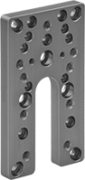
Mounting | |||||||||||||
|---|---|---|---|---|---|---|---|---|---|---|---|---|---|
Lg. | Wd. | Ht. | For Pin Dia. | Max. Load Cap., lb. | Material | Color | Fasteners Included | No. of Holes | Hole Dia. | Each | |||
| 12 1/4" | 18 1/4" | 1 1/8" | 7/8" | 100 | Powder-Coated Aluminum | Black | Yes | 8 | 13/32" | 5164T94 | 0000000 | ||
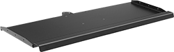 |
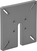
Mounting | |||||||||||||
|---|---|---|---|---|---|---|---|---|---|---|---|---|---|
Lg. | Wd. | Ht. | For Pin Dia. | Max. Load Cap., lb. | Material | Color | Fasteners Included | No. of Holes | Hole Dia. | Each | |||
| 8" | 25" | 3/4" | 7/8" | 25 | Powder-Coated Aluminum | Black | Yes | 1 | 7/8" | 5164T956 | 0000000 | ||
 |
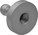
Mounting Stud | |||||||||
|---|---|---|---|---|---|---|---|---|---|
Lg. | Max. Load Cap. | Material | Color | Thread Size | Lg. | Each | |||
| 2" | Not Rated | Plastic-Coated Steel | Black | 1/4"-20 | 0.39" | 5164T945 | 00000 | ||
Lg. | Pole Dia. | Max. Load Cap., lb. | Material | Color | Each | |||
|---|---|---|---|---|---|---|---|---|
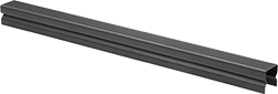
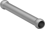
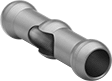
Positioning Arms | ||||||||
| 12" | 2" | 100 | Powder-Coated Steel | Black | 5164T54 | 000000 | ||
| 24" | 2" | 100 | Powder-Coated Steel | Black | 5164T946 | 00000 | ||
| 36" | 2" | 100 | Powder-Coated Steel | Black | 5164T55 | 000000 | ||
| 48" | 2" | 100 | Powder-Coated Steel | Black | 5164T947 | 000000 | ||
| 60" | 2" | 100 | Powder-Coated Steel | Black | 5164T56 | 000000 | ||
| 72" | 2" | 100 | Powder-Coated Steel | Black | 5164T948 | 000000 | ||
Pole with Cable Routing Holes | ||||||||
| 48" | 2" | 100 | Powder-Coated Steel | Black | 5164T49 | 000000 | ||
 |
Heavy Duty Ball-Grip Positioning Arms
 |
Arm Built with Base, Two Straight Connectors, Straight Link, Locking Handle, and Sensor Mount |
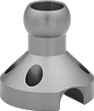
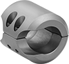
 |  |  |
Machine Vision Camera Mounting Plates, Style A | Machine Vision Camera Mounting Plates, Style B | Machine Vision Camera Mounting Plates, Style C |
 |  |  |
Machine Vision Camera Mounting Plates, Style D | Sensor Mounting Adapters, Style E | Sensor Mounting Adapters, Style F |
 |
For T-Slot Rail | Mounting | |||||||||||||
|---|---|---|---|---|---|---|---|---|---|---|---|---|---|---|
Ht. | Profile | Dia. | ID | Lg. | Max. Load Cap., lb. | Material | Color | Fasteners Included | No. of Holes | Hole Dia. | Each | |||
Rotate, Tilt, Side to Side, In/Out | ||||||||||||||
| 1", 1 1/2" | Single | 2 1/2" | 7/8" | 2 1/2" | 30 | Anodized Aluminum | Blue | Yes | 4 | 1/4" | 1530N11 | 000000 | ||
 |
Dia. | ID | Lg. | Max. Load Cap., lb. | Material | Color | Each | |||
|---|---|---|---|---|---|---|---|---|---|
Rotate, Tilt, Side to Side, In/Out | |||||||||
| 2" | 7/8" | 2" | 30 | Anodized Aluminum | Blue | 1530N12 | 000000 | ||
 |
Tilt Range of Motion | Dia. | ID | Lg. | Max. Load Cap., lb. | Material | Color | Each | |||
|---|---|---|---|---|---|---|---|---|---|---|
Rotate, Tilt, Side to Side, In/Out | ||||||||||
| 180° | 2" | 1" | 2 1/2" | 30 | Anodized Aluminum | Blue | 1530N13 | 000000 | ||
 |
Dia. | ID | Lg. | Max. Load Cap., lb. | Material | Color | Each | |||
|---|---|---|---|---|---|---|---|---|---|
Rotate, Tilt, Side to Side, In/Out | |||||||||
| 1 1/4" | 7/8" | 2 3/4" | 30 | Anodized Aluminum | Blue | 1530N15 | 000000 | ||
| 1 1/4" | 7/8" | 4 3/4" | 30 | Anodized Aluminum | Blue | 1530N16 | 00000 | ||
| 1 1/4" | 7/8" | 6 3/4" | 30 | Anodized Aluminum | Blue | 1530N17 | 00000 | ||
| 1 1/4" | 7/8" | 8 3/4" | 30 | Anodized Aluminum | Blue | 1530N18 | 00000 | ||
| 1 1/4" | 7/8" | 12 3/4" | 30 | Anodized Aluminum | Blue | 1530N19 | 00000 | ||
 |
Dia. | ID | Lg. | Max. Load Cap., lb. | Material | Color | Each | |||
|---|---|---|---|---|---|---|---|---|---|
Rotate, Tilt, Side to Side, In/Out | |||||||||
| 1 1/4" | 7/8" | 4 3/4" | 30 | Anodized Aluminum | Blue | 1530N21 | 000000 | ||
 |
Dia. | ID | Lg. | Max. Load Cap., lb. | Material | Color | Includes | Each | |||
|---|---|---|---|---|---|---|---|---|---|---|
Rotate, Tilt, Side to Side, In/Out | ||||||||||
| 1 3/8" | 5/8" | 6 3/4" to 10 3/4" | 30 | Anodized Aluminum | Blue | Adjustable Handle | 1530N34 | 0000000 | ||
 |
Mounting | ||||||||||
|---|---|---|---|---|---|---|---|---|---|---|
Lg. | Wd. | Max. Load Cap., lb. | Material | Color | Fasteners Included | No. of Holes | Each | |||
Rotate, Tilt, Side to Side, In/Out | ||||||||||
| 4 5/16" | 2 1/2" | 30 | Anodized Aluminum | Blue | Yes | 4 | 1530N24 | 000000 | ||
| | | |
Style A | Style B | Style C | Style D |
Mounting | ||||||||||||
|---|---|---|---|---|---|---|---|---|---|---|---|---|
Style | Lg. | Wd. | Max. Load Cap., lb. | Material | Color | Fasteners Included | Pattern Compatibility | No. of Holes | Each | |||
Rotate, Tilt, Side to Side, In/Out | ||||||||||||
| A | 2 3/4" | 2 1/2" | 30 | Anodized Aluminum | Blue | Yes | Cognex In-Sight 2000 Cognex In-Sight 8000 | 17 | 1530N32 | 000000 | ||
| B | 3" | 2 1/2" | 30 | Anodized Aluminum | Blue | Yes | Cognex Dataman 300 Cognex Dataman 302 Cognex Dataman 360 Cognex Dataman 470 Cognex Dataman 474 Cognex Dataman 70 Cognex In-Sight 7000 Cognex In-Sight 7800 | 17 | 1530N31 | 00000 | ||
| C | 4" | 3 1/2" | 30 | Anodized Aluminum | Blue | Yes | Smart Vision ODS75 Smart Vision ODSW75 Smart Vision S75 Smart Vision SC75 Smart Vision SW75 | 12 | 1530N33 | 00000 | ||
| D | 4 5/16" | 2 1/2" | 30 | Anodized Aluminum | Blue | Yes | DALSA BOA Cognex Checker 100 Cognex In-Sight 5000 DALSA DVT Legend 500 Cognex Dataman 100 Cognex Dataman 200 Keyence IV-500/150/2000 | 29 | 1530N23 | 00000 | ||
 |
Mounting | |||||||||||
|---|---|---|---|---|---|---|---|---|---|---|---|
Lg. | Wd. | Max. Load Cap., lb. | Material | Color | Fasteners Included | Pattern Compatibility | No. of Holes | Each | |||
Rotate, Tilt, Side to Side, In/Out | |||||||||||
| 4 1/2" | 4 1/2" | 30 | Anodized Aluminum | Blue | Yes | VESA 100 × 100 VESA 75 × 75 | 4 | 1530N27 | 000000 | ||
| |
Style E | Style F |
Style | For Sensor/Switch OD, mm | Dia. | Lg. | Max. Load Cap., lb. | Material | Color | Each | |||
|---|---|---|---|---|---|---|---|---|---|---|
Rotate, Tilt, Side to Side, In/Out | ||||||||||
| E | 18 | 1 11/32" | 3 3/4" | 30 | Anodized Aluminum | Blue | 1530N26 | 000000 | ||
| E | 30 | 1 3/4" | 3 3/4" | 30 | Anodized Aluminum | Blue | 1530N25 | 00000 | ||
| F | 8 | 3/4" | 2 1/4" | 30 | Anodized Aluminum | Blue | 1530N29 | 00000 | ||
| F | 12 | 3/4" | 2 1/4" | 30 | Anodized Aluminum | Blue | 1530N28 | 00000 | ||
 |
For Sensor/Switch OD, mm | Dia. | Lg. | Max. Load Cap., lb. | Material | Color | Each | |||
|---|---|---|---|---|---|---|---|---|---|
Rotate, Tilt, Side to Side, In/Out | |||||||||
| 30 | 3 1/2" | 3 3/4" | 30 | Anodized Aluminum | Blue | 1530N22 | 000000 | ||
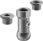 |
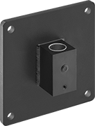
Air Connection | |||||||||||||
|---|---|---|---|---|---|---|---|---|---|---|---|---|---|
Dia. | Lg. | Max. Load Cap., lb. | Material | Color | Pipe Size | Thread Type | Gender | Mounting Hole Pipe Size (Mounting Hole Thread Type) | Mounting Hole Screw Size | Each | |||
Rotate, Tilt, Side to Side, In/Out | |||||||||||||
| 1 1/4" | 3 1/16" | 30 | Anodized Aluminum | Blue | 1/2 | BSPP | Female | 1/4 (BSPP); 3/8 (BSPP); 1/2 (BSPP) | M8 | 1530N222 | 0000000 | ||
 |
Mounting Stud | ||||||||
|---|---|---|---|---|---|---|---|---|
Lg. | Material | Color | Thread Size | Lg. | Each | |||
Rotate, Tilt, Side to Side, In/Out | ||||||||
| 2" | Steel | Black | 10-24 | 1" | 1530N14 | 000000 | ||
Articulating Desktop Cranes
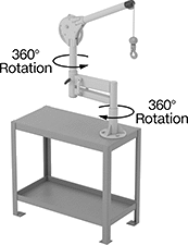 |
Cranes | Crane Bases | ||||||||||||||||||
|---|---|---|---|---|---|---|---|---|---|---|---|---|---|---|---|---|---|---|---|
Wt. Cap. | Arm Lg. | Lift Lg., ft. | Overall Ht. | Rotation | Fasteners Included | Mounting Hole Dia. | Wire Rope Material | Hook Type | Hook Material | Hook Movement | Hook Opening Wd. | No. of Mounting Holes | Specs. Met | Each | Each | ||||
Powder-Coated Steel | |||||||||||||||||||
| 1/4 ton, 500 lb. | 36" | 8 | 42" | 360° | No | 9/16" | Steel | Latching | Steel | 360° Swivel | 5/8" | 3 | ASME B30.16, ASME HST-3, OSHA Compliant 29 CFR 1926.1501 | 7465N101 | 000000000 | 3276T93 | 0000000 | ||
