


Filter by
For Use With
Outlet Pressure
Maximum Inlet Pressure
Body Material
Maximum Outlet Pressure Gauge Measurement
Maximum Pressure
Valve Function
Outlet Thread Type
Connects To
Set Pressure
Maximum Temperature
DFARS Specialty Metals
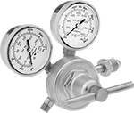
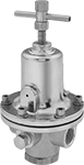
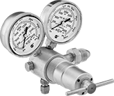
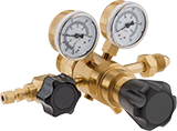
Panel-Mount High-Pressure-Regulating Valves for Air and Inert Gas
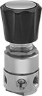 |
Withstand inlet pressures up to 3,500 psi. These valves automatically reduce a high, variable inlet pressure to a lower, stable outlet pressure. Adjust the outlet pressure within the range. Valves have threads below the adjustment knob and come with a panel-mount nut. All have two gauge ports. An internal strainer traps debris.
Inlet | Outlet | Gauge Port | |||||||||||||||||||||||||||||||||||||||||||||||||||||||||||||||||||||||||||||||||||||||||||||||||
|---|---|---|---|---|---|---|---|---|---|---|---|---|---|---|---|---|---|---|---|---|---|---|---|---|---|---|---|---|---|---|---|---|---|---|---|---|---|---|---|---|---|---|---|---|---|---|---|---|---|---|---|---|---|---|---|---|---|---|---|---|---|---|---|---|---|---|---|---|---|---|---|---|---|---|---|---|---|---|---|---|---|---|---|---|---|---|---|---|---|---|---|---|---|---|---|---|---|---|---|
Pipe Size | Location | Max. Pressure, psi | Pipe Size | Location | Pressure Adjustment Method | Pressure Gauge Included | Pipe Size | Location | Connection | End-to-End Lg. | Panel Cutout Dia. | For Use With | Temp. Range, ° F | Specs. Met | Choose an Outlet Pressure, psi | Each | |||||||||||||||||||||||||||||||||||||||||||||||||||||||||||||||||||||||||||||||||||
NPT Female | |||||||||||||||||||||||||||||||||||||||||||||||||||||||||||||||||||||||||||||||||||||||||||||||||||
Brass Body—316 Stainless Steel Diaphragm and PTFE Seal with Internal Strainer | |||||||||||||||||||||||||||||||||||||||||||||||||||||||||||||||||||||||||||||||||||||||||||||||||||
| 1/4 | Side | 3,500 | 1/4 | Side | Knob | No | 1/4 | Side | NPT Female | 2" | 1 3/8" | Air, Nitrogen, Argon, Helium | -40 to 165 | ASME B31.3 | 0 to 25 , 0 to 50 , 0 to 100 , 0 to 250 , 0 to 500 | 0000000 | 0000000 | ||||||||||||||||||||||||||||||||||||||||||||||||||||||||||||||||||||||||||||||||||
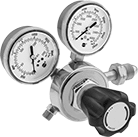
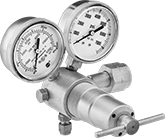
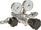
Panel-Mount Ultra-High-Pressure-Regulating Valves for Air and Inert Gas
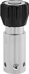 |
These valves are rated for inlet pressures up to 6,000 psi. They automatically reduce a high, variable inlet pressure to a lower, stable outlet pressure. Adjust the outlet pressure within the range. Threads below the adjustment knob and an included mounting bracket let you install these valves in instrument panels. They have two gauge ports. An internal strainer traps debris.
Inlet | Outlet | Gauge Port | |||||||||||||||||||||||||||||||||||||||||||||||||||||||||||||||||||||||||||||||||||||||||||||||||
|---|---|---|---|---|---|---|---|---|---|---|---|---|---|---|---|---|---|---|---|---|---|---|---|---|---|---|---|---|---|---|---|---|---|---|---|---|---|---|---|---|---|---|---|---|---|---|---|---|---|---|---|---|---|---|---|---|---|---|---|---|---|---|---|---|---|---|---|---|---|---|---|---|---|---|---|---|---|---|---|---|---|---|---|---|---|---|---|---|---|---|---|---|---|---|---|---|---|---|---|
Pipe Size | Location | Max. Pressure, psi | Pipe Size | Location | Pressure Adjustment Method | Pressure Gauge Included | Pipe Size | Location | Connection | End-to-End Lg. | Panel Cutout Dia. | For Use With | Temp. Range, ° F | Specs. Met | Choose an Outlet Pressure, psi | Each | |||||||||||||||||||||||||||||||||||||||||||||||||||||||||||||||||||||||||||||||||||
NPT Female | |||||||||||||||||||||||||||||||||||||||||||||||||||||||||||||||||||||||||||||||||||||||||||||||||||
Brass Body—Polyimide Seal with Internal Strainer | |||||||||||||||||||||||||||||||||||||||||||||||||||||||||||||||||||||||||||||||||||||||||||||||||||
| 1/4 | Side | 6,000 | 1/4 | Side | Knob | No | 1/4 | Side | NPT Female | 2 1/8" | 2 1/4" | Air, Nitrogen, Argon, Helium | -40 to 165 | ASME B31.3 | 0 to 500 , 0 to 800 , 10 to 1,500 , 15 to 2,500 , 25 to 4,000 , 50 to 6,000 | 0000000 | 000000000 | ||||||||||||||||||||||||||||||||||||||||||||||||||||||||||||||||||||||||||||||||||
Tank-Mount Pressure-Regulating Valves for Air and Inert Gas
Single Stage
 |  |  |  |
Female Outlet × Male Inlet Single-Stage Valves with T-Handle | Flared Outlet × Male Inlet Single-Stage Valves | UNF Male Outlet x Male Inlet Single-Stage Valves with T-Handle | UNF Male Outlet × Male Inlet Single-Stage Valves With Knob |
Inlet | Outlet | Material | |||||||||||||||||||||||||||||||||||||||||||||||||||||||||||||||||||||||||||||||||||||||||||||||||
|---|---|---|---|---|---|---|---|---|---|---|---|---|---|---|---|---|---|---|---|---|---|---|---|---|---|---|---|---|---|---|---|---|---|---|---|---|---|---|---|---|---|---|---|---|---|---|---|---|---|---|---|---|---|---|---|---|---|---|---|---|---|---|---|---|---|---|---|---|---|---|---|---|---|---|---|---|---|---|---|---|---|---|---|---|---|---|---|---|---|---|---|---|---|---|---|---|---|---|---|
CGA No. | Location | Thread Direction | Pressure Gauge Reading Range, psi | Location | Thread Direction | Pressure Range, psi | Pressure Adjustment Method | Body | Seal | Diaphragm | Temp. Range, ° F | Each | |||||||||||||||||||||||||||||||||||||||||||||||||||||||||||||||||||||||||||||||||||||||
For Argon, Helium, and Nitrogen | |||||||||||||||||||||||||||||||||||||||||||||||||||||||||||||||||||||||||||||||||||||||||||||||||||
37° Flared UNF Male Outlet × NGO Male Inlet | |||||||||||||||||||||||||||||||||||||||||||||||||||||||||||||||||||||||||||||||||||||||||||||||||||
| 580 | Side | Right Hand | 0 to 4,000 | Side | Right Hand | 10 to 200 | — | Brass | Polyurethane Rubber | Neoprene/Nylon | -20 to 120 | 00000000 | 0000000 | ||||||||||||||||||||||||||||||||||||||||||||||||||||||||||||||||||||||||||||||||||||||
45° Flared UN/UNF (SAE 45°) Male Outlet × NGO Male Inlet | |||||||||||||||||||||||||||||||||||||||||||||||||||||||||||||||||||||||||||||||||||||||||||||||||||
| 580 | Side | Right Hand | 0 to 4,000 | Side | Right Hand | 0 to 250 | T-Handle | Brass | PTFE | Neoprene | -20 to 120 | 00000000 | 000000 | ||||||||||||||||||||||||||||||||||||||||||||||||||||||||||||||||||||||||||||||||||||||
| 580 | Side | Right Hand | 0 to 4,000 | Side | Right Hand | 0 to 500 | T-Handle | Brass | PTFE | Neoprene | -20 to 120 | 00000000 | 000000 | ||||||||||||||||||||||||||||||||||||||||||||||||||||||||||||||||||||||||||||||||||||||
5/8"-18 UNF Female Outlet × NGO Male Inlet | |||||||||||||||||||||||||||||||||||||||||||||||||||||||||||||||||||||||||||||||||||||||||||||||||||
| 580 | Side | Right Hand | 0 to 4,000 | Side | Right Hand | 0 to 125 | T-Handle | Brass | PTFE | Stainless Steel | -20 to 120 | 00000000 | 000000 | ||||||||||||||||||||||||||||||||||||||||||||||||||||||||||||||||||||||||||||||||||||||
9/16"-18 UNF Male Outlet × NGO Male Inlet | |||||||||||||||||||||||||||||||||||||||||||||||||||||||||||||||||||||||||||||||||||||||||||||||||||
| 580 | Side | Right Hand | 0 to 4,000 | Side | Right Hand | 0 to 50 | T-Handle | Brass | PTFE | Neoprene | -20 to 120 | 00000000 | 000000 | ||||||||||||||||||||||||||||||||||||||||||||||||||||||||||||||||||||||||||||||||||||||
| 580 | Side | Right Hand | 0 to 4,000 | Side | Right Hand | 0 to 125 | T-Handle | Brass | PTFE | Rubber | -20 to 120 | 0000000 | 000000 | ||||||||||||||||||||||||||||||||||||||||||||||||||||||||||||||||||||||||||||||||||||||
| 580 | Side | Right Hand | 0 to 4,000 | Side | Right Hand | 0 to 145 | Knob | Brass/Steel | PTFE | Rubber | -20 to 120 | 0000000 | 000000 | ||||||||||||||||||||||||||||||||||||||||||||||||||||||||||||||||||||||||||||||||||||||
| 580 | Side | Right Hand | 0 to 4,000 | Side | Right Hand | 0 to 200 | T-Handle | Brass | PTFE | Rubber | -20 to 120 | 0000000 | 000000 | ||||||||||||||||||||||||||||||||||||||||||||||||||||||||||||||||||||||||||||||||||||||
Two Stage
 |  |
NPT Female Outlet × Male Inlet Two-Stage Valves with T-Handle | UNF Female Outlet x Male Inlet Two-Stage Valves with T-Handle |
Two-stage valves progressively reduce pressure over two steps for more consistent outlet pressure at all times. They’re often used in applications that require a constant outlet pressure regardless of the tank level.
Brass Body—Valves with a brass body have a longer service life than valves with a brass and steel body.
Stainless Steel Diaphragm—Valves with a stainless steel diaphragm can withstand harsh environments.
Inlet | Outlet | Material | |||||||||||||||||||||||||||||||||||||||||||||||||||||||||||||||||||||||||||||||||||||||||||||||||
|---|---|---|---|---|---|---|---|---|---|---|---|---|---|---|---|---|---|---|---|---|---|---|---|---|---|---|---|---|---|---|---|---|---|---|---|---|---|---|---|---|---|---|---|---|---|---|---|---|---|---|---|---|---|---|---|---|---|---|---|---|---|---|---|---|---|---|---|---|---|---|---|---|---|---|---|---|---|---|---|---|---|---|---|---|---|---|---|---|---|---|---|---|---|---|---|---|---|---|---|
CGA No. | Location | Thread Direction | Pressure Gauge Reading Range, psi | Location | Thread Direction | Pressure Range, psi | Pressure Adjustment Method | Body | Seal | Diaphragm | Temp. Range, ° F | Each | |||||||||||||||||||||||||||||||||||||||||||||||||||||||||||||||||||||||||||||||||||||||
For Argon, Helium, and Nitrogen | |||||||||||||||||||||||||||||||||||||||||||||||||||||||||||||||||||||||||||||||||||||||||||||||||||
1/4 NPT Female Outlet × NGO Male Inlet | |||||||||||||||||||||||||||||||||||||||||||||||||||||||||||||||||||||||||||||||||||||||||||||||||||
| 580 | Side | Right Hand | 0 to 4,000 | Side | Right Hand | 0 to 250 | T-Handle | Brass | PTFE | Neoprene | -20 to 120 | 00000000 | 0000000 | ||||||||||||||||||||||||||||||||||||||||||||||||||||||||||||||||||||||||||||||||||||||
| 580 | Side | Right Hand | 0 to 4,000 | Side | Right Hand | 0 to 250 | T-Handle | Brass | PTFE | Stainless Steel | -20 to 120 | 00000000 | 000000 | ||||||||||||||||||||||||||||||||||||||||||||||||||||||||||||||||||||||||||||||||||||||
5/8"-18 UNF Female Outlet × NGO Male Inlet | |||||||||||||||||||||||||||||||||||||||||||||||||||||||||||||||||||||||||||||||||||||||||||||||||||
| 580 | Side | Right Hand | 0 to 4,000 | Side | Right Hand | 0 to 50 | T-Handle | Brass | PTFE | Neoprene | -20 to 120 | 00000000 | 000000 | ||||||||||||||||||||||||||||||||||||||||||||||||||||||||||||||||||||||||||||||||||||||
| 580 | Side | Right Hand | 0 to 4,000 | Side | Right Hand | 0 to 50 | T-Handle | Brass | PTFE | Stainless Steel | -20 to 120 | 0000000 | 000000 | ||||||||||||||||||||||||||||||||||||||||||||||||||||||||||||||||||||||||||||||||||||||
| 580 | Side | Right Hand | 0 to 4,000 | Side | Right Hand | 0 to 125 | T-Handle | Brass/Steel | PTFE | Rubber | -20 to 120 | 0000000 | 000000 | ||||||||||||||||||||||||||||||||||||||||||||||||||||||||||||||||||||||||||||||||||||||
| 580 | Side | Right Hand | 0 to 4,000 | Side | Right Hand | 0 to 125 | T-Handle | Brass | PTFE | Stainless Steel | -20 to 120 | 0000000 | 000000 | ||||||||||||||||||||||||||||||||||||||||||||||||||||||||||||||||||||||||||||||||||||||
Cleaned and Bagged Pressure-Regulating Valves for Air and Inert Gas
 |
Often used for oxygen service and other high-purity applications, these valves are cleaned and bagged to meet CGA G-4.1 standards to prevent contamination. They automatically reduce a high, variable inlet pressure to a lower, stable outlet pressure. Adjust the outlet pressure within the range. Valves have two gauge ports. They are no-bleed style, so they keep process gases contained in the valve.
Inlet | Outlet | Gauge Port | |||||||||||||||||||||||||||||||||||||||||||||||||||||||||||||||||||||||||||||||||||||||||||||||||
|---|---|---|---|---|---|---|---|---|---|---|---|---|---|---|---|---|---|---|---|---|---|---|---|---|---|---|---|---|---|---|---|---|---|---|---|---|---|---|---|---|---|---|---|---|---|---|---|---|---|---|---|---|---|---|---|---|---|---|---|---|---|---|---|---|---|---|---|---|---|---|---|---|---|---|---|---|---|---|---|---|---|---|---|---|---|---|---|---|---|---|---|---|---|---|---|---|---|---|---|
Pipe Size | Location | Max. Pressure, psi | Pipe Size | Location | Pressure Adjustment Method | Pressure Gauge Included | Pipe Size | Location | Connection | End-to-End Lg. | For Use With | Temp. Range, ° F | Specs. Met | Choose an Outlet Pressure, psi | Each | ||||||||||||||||||||||||||||||||||||||||||||||||||||||||||||||||||||||||||||||||||||
NPT Female | |||||||||||||||||||||||||||||||||||||||||||||||||||||||||||||||||||||||||||||||||||||||||||||||||||
Brass Body—Buna-N Diaphragm and Fluoroelastomer Seal | |||||||||||||||||||||||||||||||||||||||||||||||||||||||||||||||||||||||||||||||||||||||||||||||||||
| 1/2 | Side | 500 | 1/2 | Side | T-Handle | No | 1/4 | Side | NPT Female | 2 13/16" | Nitrogen, Oxygen, Argon, Helium, Neon | -40 to 165 | CGA G-4.1 | 5 to 55 , 40 to 110 , 100 to 200 , 175 to 300 | 00000000 | 0000000 | |||||||||||||||||||||||||||||||||||||||||||||||||||||||||||||||||||||||||||||||||||
| 3/4 | Side | 500 | 3/4 | Side | T-Handle | No | 1/4 | Side | NPT Female | 3 5/16" | Nitrogen, Oxygen, Argon, Helium, Neon | -40 to 165 | CGA G-4.1 | 5 to 55 , 40 to 110 , 100 to 200 , 175 to 275 | 00000000 | 000000 | |||||||||||||||||||||||||||||||||||||||||||||||||||||||||||||||||||||||||||||||||||
| 1 | Side | 500 | 1 | Side | T-Handle | No | 1/4 | Side | NPT Female | 3 5/16" | Nitrogen, Oxygen, Argon, Helium, Neon | -40 to 165 | CGA G-4.1 | 5 to 55 , 40 to 110 , 100 to 200 , 175 to 275 | 00000000 | 000000 | |||||||||||||||||||||||||||||||||||||||||||||||||||||||||||||||||||||||||||||||||||
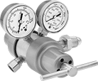
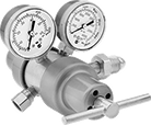
Cleaned and Bagged Panel-Mount Pressure-Regulating Valves for Air and Inert Gas
Commonly used for oxygen service and other high-purity applications, these valves come cleaned and bagged to prevent contamination. All automatically reduce a high, variable inlet pressure to a lower, stable outlet pressure. Adjust the outlet pressure within the range. Valves have threads below the adjustment knob and come with a panel-mount nut. They can also be surface mounted. All have two gauge ports. Body is 316 stainless steel for exceptional corrosion resistance. Valves are no-bleed style, so they keep process gases contained in the valve.
Inlet | Outlet | Gauge Port | |||||||||||||||||||||||||||||||||||||||||||||||||||||||||||||||||||||||||||||||||||||||||||||||||
|---|---|---|---|---|---|---|---|---|---|---|---|---|---|---|---|---|---|---|---|---|---|---|---|---|---|---|---|---|---|---|---|---|---|---|---|---|---|---|---|---|---|---|---|---|---|---|---|---|---|---|---|---|---|---|---|---|---|---|---|---|---|---|---|---|---|---|---|---|---|---|---|---|---|---|---|---|---|---|---|---|---|---|---|---|---|---|---|---|---|---|---|---|---|---|---|---|---|---|---|
Pipe Size | Location | Max. Pressure, psi | Pipe Size | Location | Pressure Range, psi | Pressure Adjustment Method | Pressure Gauge Included | Pipe Size | Location | Connection | End-to-End Lg. | Panel Cutout Dia. | For Use With | Temp. Range, ° F | Each | ||||||||||||||||||||||||||||||||||||||||||||||||||||||||||||||||||||||||||||||||||||
NPT Female | |||||||||||||||||||||||||||||||||||||||||||||||||||||||||||||||||||||||||||||||||||||||||||||||||||
316 Stainless Steel Body—316 Stainless Steel Diaphragm and PTFE Seal | |||||||||||||||||||||||||||||||||||||||||||||||||||||||||||||||||||||||||||||||||||||||||||||||||||
| 1/4 | Side | 3,500 | 1/4 | Side | 0 to 25 | Knob | No | 1/4 | Side | NPT Female | 5 3/8" | 1.37" | Air, Nitrogen, Argon, Helium | -40 to 165 | 0000000 | 0000000 | |||||||||||||||||||||||||||||||||||||||||||||||||||||||||||||||||||||||||||||||||||
| 1/4 | Side | 3,500 | 1/4 | Side | 0 to 100 | Knob | No | 1/4 | Side | NPT Female | 5 3/8" | 1.37" | Air, Nitrogen, Argon, Helium | -40 to 165 | 0000000 | 000000 | |||||||||||||||||||||||||||||||||||||||||||||||||||||||||||||||||||||||||||||||||||
| 1/4 | Side | 3,500 | 1/4 | Side | 0 to 250 | Knob | No | 1/4 | Side | NPT Female | 5 3/8" | 1.37" | Air, Nitrogen, Argon, Helium | -40 to 165 | 0000000 | 000000 | |||||||||||||||||||||||||||||||||||||||||||||||||||||||||||||||||||||||||||||||||||
| 1/4 | Side | 3,500 | 1/4 | Side | 0 to 500 | Knob | No | 1/4 | Side | NPT Female | 5 3/8" | 1.37" | Air, Nitrogen, Argon, Helium | -40 to 165 | 0000000 | 000000 | |||||||||||||||||||||||||||||||||||||||||||||||||||||||||||||||||||||||||||||||||||
| 1/2 | Side | 500 | 1/2 | Side | 0 to 25 | Knob | No | 1/4 | Side | NPT Female | 5 1/2" | 1.37" | Air, Nitrogen, Argon, Helium | -40 to 165 | 0000000 | 00000000 | |||||||||||||||||||||||||||||||||||||||||||||||||||||||||||||||||||||||||||||||||||
| 1/2 | Side | 500 | 1/2 | Side | 0 to 100 | Knob | No | 1/4 | Side | NPT Female | 5 1/2" | 1.37" | Air, Nitrogen, Argon, Helium | -40 to 165 | 0000000 | 00000000 | |||||||||||||||||||||||||||||||||||||||||||||||||||||||||||||||||||||||||||||||||||
| 1/2 | Side | 500 | 1/2 | Side | 0 to 150 | Knob | No | 1/4 | Side | NPT Female | 5 1/2" | 1.37" | Air, Nitrogen, Argon, Helium | -40 to 165 | 0000000 | 00000000 | |||||||||||||||||||||||||||||||||||||||||||||||||||||||||||||||||||||||||||||||||||
Tank-Mount High-Pressure-Regulating Valves for Air and Inert Gas
For Argon, Helium, and Nitrogen
 |  |
Female Outlet × Female Inlet Elbow With T-Handle | Female Outlet × Male Inlet Elbow With T-Handle |
Inlet | Outlet | Material | |||||||||||||||||||||||||||||||||||||||||||||||||||||||||||||||||||||||||||||||||||||||||||||||||
|---|---|---|---|---|---|---|---|---|---|---|---|---|---|---|---|---|---|---|---|---|---|---|---|---|---|---|---|---|---|---|---|---|---|---|---|---|---|---|---|---|---|---|---|---|---|---|---|---|---|---|---|---|---|---|---|---|---|---|---|---|---|---|---|---|---|---|---|---|---|---|---|---|---|---|---|---|---|---|---|---|---|---|---|---|---|---|---|---|---|---|---|---|---|---|---|---|---|---|---|
CGA No. | Location | Thread Direction | Pressure Gauge Reading Range, psi | No. of Stages | For Tube OD | Location | Pressure Range, psi | Pressure Adjustment Method | Shape | Body | Seal | Temp. Range, ° F | Each | ||||||||||||||||||||||||||||||||||||||||||||||||||||||||||||||||||||||||||||||||||||||
NGO Female Inlet × Swagelok® Female Outlet | |||||||||||||||||||||||||||||||||||||||||||||||||||||||||||||||||||||||||||||||||||||||||||||||||||
| 677 | Side | Left Hand | 0 to 7,500 | Single | 1/4" | Bottom | 300 to 4,500 | T-Handle | 90° Elbow | Brass | PCTFE | -20 to 120 | 0000000 | 000000000 | |||||||||||||||||||||||||||||||||||||||||||||||||||||||||||||||||||||||||||||||||||||
NGO Male Inlet × Swagelok® Female Outlet | |||||||||||||||||||||||||||||||||||||||||||||||||||||||||||||||||||||||||||||||||||||||||||||||||||
| 580 | Side | Right Hand | 0 to 4,000 | Single | 1/4" | Bottom | 200 to 3,000 | T-Handle | 90° Elbow | Brass | PCTFE | -20 to 120 | 0000000 | 000000 | |||||||||||||||||||||||||||||||||||||||||||||||||||||||||||||||||||||||||||||||||||||
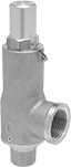
ASME-Code Fast-Acting Pressure-Relief Valves for Cryogenic Fluids
NPT Male Inlet and NPT Female Relief Port
 |
Inlet | Relief | ||||||||||||||||||||||||||||||||||||||||||||||||||||||||||||||||||||||||||||||||||||||||||||||||||
|---|---|---|---|---|---|---|---|---|---|---|---|---|---|---|---|---|---|---|---|---|---|---|---|---|---|---|---|---|---|---|---|---|---|---|---|---|---|---|---|---|---|---|---|---|---|---|---|---|---|---|---|---|---|---|---|---|---|---|---|---|---|---|---|---|---|---|---|---|---|---|---|---|---|---|---|---|---|---|---|---|---|---|---|---|---|---|---|---|---|---|---|---|---|---|---|---|---|---|---|
Pipe Size | Location | Max. Pressure, psi | Port Pipe Size | Port Location | Shape | Overall Ht. | For Use With | Temp. Range, ° F | Valve Type | Certification | Choose a Set Pressure, psi | Each | |||||||||||||||||||||||||||||||||||||||||||||||||||||||||||||||||||||||||||||||||||||||
Brass Body—Brass Seal | |||||||||||||||||||||||||||||||||||||||||||||||||||||||||||||||||||||||||||||||||||||||||||||||||||
| 1/2 | Bottom | 600 | 3/4 | Side | 90° Elbow | 6 9/16" | Argon, Carbon Dioxide, Helium, Hydrogen, Methane, Nitrogen, Oxygen | -320 to 150 | Pop Safety | ASME BPVC.VIII | 20 , 30 , 40 , 50 , 60 , 70 , 80 , 90 , 100 , 110 , 120 , 130 , 140 , 150 , 160 , 170 , 180 , 190 , 200 , 210 , 220 , 230 , 240 , 250 , 260 , 270 , 280 , 290 , 300 | 0000000 | 0000000 | ||||||||||||||||||||||||||||||||||||||||||||||||||||||||||||||||||||||||||||||||||||||
| 3/4 | Bottom | 600 | 1 | Side | 90° Elbow | 6 9/16" | Argon, Carbon Dioxide, Helium, Hydrogen, Methane, Nitrogen, Oxygen | -320 to 150 | Pop Safety | ASME BPVC.VIII | 20 , 30 , 40 , 50 , 60 , 70 , 80 , 90 , 100 , 110 , 120 , 130 , 140 , 150 , 160 , 170 , 180 , 190 , 200 , 210 , 220 , 230 , 240 , 250 , 260 , 270 , 280 , 290 , 300 | 0000000 | 000000 | ||||||||||||||||||||||||||||||||||||||||||||||||||||||||||||||||||||||||||||||||||||||
High-Purity Tank-Mount Pressure-Regulating Valves for Inert Gas
For Argon, Helium, and Nitrogen
 |  |
Swagelok® Female Outlet × NGO Male Inlet (Brass) | Swagelok® Female Outlet × NGO Male Inlet (Chrome-Plated Brass) |
Chrome-Plated Brass Body—Chrome-plated valves add a layer of corrosion resistance.
Single Stage—Single-stage valves reduce pressure in one step, which causes the outlet pressure to fluctuate slightly as you empty the tank. They’re best for applications where a constant outlet pressure isn’t critical.
Two Stage—Two-stage valves progressively reduce pressure over two steps for more consistent outlet pressure at all times. They’re often used in applications that require a constant outlet pressure regardless of the tank level.
Inlet | Outlet | ||||||||||||||||||||||||||||||||||||||||||||||||||||||||||||||||||||||||||||||||||||||||||||||||||
|---|---|---|---|---|---|---|---|---|---|---|---|---|---|---|---|---|---|---|---|---|---|---|---|---|---|---|---|---|---|---|---|---|---|---|---|---|---|---|---|---|---|---|---|---|---|---|---|---|---|---|---|---|---|---|---|---|---|---|---|---|---|---|---|---|---|---|---|---|---|---|---|---|---|---|---|---|---|---|---|---|---|---|---|---|---|---|---|---|---|---|---|---|---|---|---|---|---|---|---|
CGA No. | Location | Thread Direction | Pressure Gauge Reading Range, psi | No. of Stages | For Tube OD | Location | Pressure Range, psi | Pressure Adjustment Method | Temp. Range, ° F | Each | |||||||||||||||||||||||||||||||||||||||||||||||||||||||||||||||||||||||||||||||||||||||||
NGO Male Inlet × Swagelok® Female Outlet | |||||||||||||||||||||||||||||||||||||||||||||||||||||||||||||||||||||||||||||||||||||||||||||||||||
Brass Body—316 Stainless Steel Diaphragm and PTFE Seal | |||||||||||||||||||||||||||||||||||||||||||||||||||||||||||||||||||||||||||||||||||||||||||||||||||
| 580 | Side | Right Hand | 0 to 4,000 | Single | 1/4" | Side | 0 to 15 | Knob | -20 to 120 | 0000000 | 0000000 | ||||||||||||||||||||||||||||||||||||||||||||||||||||||||||||||||||||||||||||||||||||||||
| 580 | Side | Right Hand | 0 to 4,000 | Single | 1/4" | Side | 0 to 125 | Knob | -20 to 120 | 0000000 | 000000 | ||||||||||||||||||||||||||||||||||||||||||||||||||||||||||||||||||||||||||||||||||||||||
| 580 | Side | Right Hand | 0 to 4,000 | Single | 1/4" | Side | 0 to 500 | Knob | -20 to 120 | 0000000 | 000000 | ||||||||||||||||||||||||||||||||||||||||||||||||||||||||||||||||||||||||||||||||||||||||
| 580 | Side | Right Hand | 0 to 4,000 | Two | 1/4" | Side | 0 to 15 | Knob | -20 to 120 | 0000000 | 000000 | ||||||||||||||||||||||||||||||||||||||||||||||||||||||||||||||||||||||||||||||||||||||||
| 580 | Side | Right Hand | 0 to 4,000 | Two | 1/4" | Side | 0 to 50 | Knob | -20 to 120 | 0000000 | 000000 | ||||||||||||||||||||||||||||||||||||||||||||||||||||||||||||||||||||||||||||||||||||||||
| 580 | Side | Right Hand | 0 to 4,000 | Two | 1/4" | Side | 0 to 125 | Knob | -20 to 120 | 0000000 | 000000 | ||||||||||||||||||||||||||||||||||||||||||||||||||||||||||||||||||||||||||||||||||||||||
| 580 | Side | Right Hand | 0 to 4,000 | Two | 1/4" | Side | 0 to 250 | Knob | -20 to 120 | 0000000 | 000000 | ||||||||||||||||||||||||||||||||||||||||||||||||||||||||||||||||||||||||||||||||||||||||
Chrome-Plated Brass Body—316 Stainless Steel Diaphragm and PTFE Seal | |||||||||||||||||||||||||||||||||||||||||||||||||||||||||||||||||||||||||||||||||||||||||||||||||||
| 580 | Side | Right Hand | 0 to 4,000 | Two | 1/4" | Side | 0 to 50 | Knob | -20 to 120 | 0000000 | 000000 | ||||||||||||||||||||||||||||||||||||||||||||||||||||||||||||||||||||||||||||||||||||||||
Vacuum Breakers for Chemicals
Diaphragm Check Valve
 |
Material | CPVC Body | PVC Body | |||||||||||||||||||||||||||||||||||||||||||||||||||||||||||||||||||||||||||||||||||||||||||||||||
|---|---|---|---|---|---|---|---|---|---|---|---|---|---|---|---|---|---|---|---|---|---|---|---|---|---|---|---|---|---|---|---|---|---|---|---|---|---|---|---|---|---|---|---|---|---|---|---|---|---|---|---|---|---|---|---|---|---|---|---|---|---|---|---|---|---|---|---|---|---|---|---|---|---|---|---|---|---|---|---|---|---|---|---|---|---|---|---|---|---|---|---|---|---|---|---|---|---|---|---|
Inlet Pipe Size | Outlet Pipe SIze | For Pipe Schedule | Flow Coefficient (Cv) | Max. Pressure @ Temp. | Min. Opening Pressure, psi | End-to-End Lg. | Seal | DIaphragm | For Use With | Temp. Range, ° F | Color | Each | Temp. Range, ° F | Color | Each | ||||||||||||||||||||||||||||||||||||||||||||||||||||||||||||||||||||||||||||||||||||
NPT Female Inlet × NPT Female Outlet | |||||||||||||||||||||||||||||||||||||||||||||||||||||||||||||||||||||||||||||||||||||||||||||||||||
| 1/2 | 1/2 | 80 | Not Rated | 100 psi @ 75° F | 1 | 4 5/16" | Fluoroelastomer | Fluoroelastomer | Beverage, Food, Air, Ammonia, Argon, Carbon Dioxide, Chlorinated Water, Diesel Fuel, Drinking Water, Ethylene Glycol, Helium, Hydrochloric Acid, Kerosene, Krypton, Liquid Carbon Dioxide, Methanol (Methyl Alcohol), Methyl Ethyl Ketone (MEK), Mineral Spirits, Natural Gas, Neon, Nitric Acid, Nitrogen, Oil, Oxygen, Soap Solutions, Sodium Hydroxide (Caustic Soda), Sodium Hypochlorite (Bleach), Water, Xenon | 40 to 180 | Light Gray | 0000000 | 0000000 | 40 to 140 | Gray | 000000 | 0000000 | ||||||||||||||||||||||||||||||||||||||||||||||||||||||||||||||||||||||||||||||||||
| 3/4 | 3/4 | 80 | Not Rated | 100 psi @ 75° F | 1 | 4 5/8" | Fluoroelastomer | Fluoroelastomer | Beverage, Food, Air, Ammonia, Argon, Carbon Dioxide, Chlorinated Water, Diesel Fuel, Drinking Water, Ethylene Glycol, Helium, Hydrochloric Acid, Kerosene, Krypton, Liquid Carbon Dioxide, Methanol (Methyl Alcohol), Methyl Ethyl Ketone (MEK), Mineral Spirits, Natural Gas, Neon, Nitric Acid, Nitrogen, Oil, Oxygen, Soap Solutions, Sodium Hydroxide (Caustic Soda), Sodium Hypochlorite (Bleach), Water, Xenon | 40 to 180 | Light Gray | 0000000 | 000000 | 40 to 140 | Gray | 0000000 | 000000 | ||||||||||||||||||||||||||||||||||||||||||||||||||||||||||||||||||||||||||||||||||
| 1 | 1 | 80 | Not Rated | 100 psi @ 75° F | 1 | 5 1/8" | Fluoroelastomer | Fluoroelastomer | Beverage, Food, Air, Ammonia, Argon, Carbon Dioxide, Chlorinated Water, Diesel Fuel, Drinking Water, Ethylene Glycol, Helium, Hydrochloric Acid, Kerosene, Krypton, Liquid Carbon Dioxide, Methanol (Methyl Alcohol), Methyl Ethyl Ketone (MEK), Mineral Spirits, Natural Gas, Neon, Nitric Acid, Nitrogen, Oil, Oxygen, Soap Solutions, Sodium Hydroxide (Caustic Soda), Sodium Hypochlorite (Bleach), Water, Xenon | 40 to 180 | Light Gray | 0000000 | 000000 | 40 to 140 | Gray | 0000000 | 000000 | ||||||||||||||||||||||||||||||||||||||||||||||||||||||||||||||||||||||||||||||||||
Spring-Loaded Piston Check Valve
|
Material | CPVC Body | PVC Body | |||||||||||||||||||||||||||||||||||||||||||||||||||||||||||||||||||||||||||||||||||||||||||||||||
|---|---|---|---|---|---|---|---|---|---|---|---|---|---|---|---|---|---|---|---|---|---|---|---|---|---|---|---|---|---|---|---|---|---|---|---|---|---|---|---|---|---|---|---|---|---|---|---|---|---|---|---|---|---|---|---|---|---|---|---|---|---|---|---|---|---|---|---|---|---|---|---|---|---|---|---|---|---|---|---|---|---|---|---|---|---|---|---|---|---|---|---|---|---|---|---|---|---|---|---|
Inlet Pipe Size | Outlet Pipe SIze | For Pipe Schedule | Flow Coefficient (Cv) | Max. Pressure @ Temp. | Min. Opening Pressure, psi | End-to-End Lg. | Seal | Piston | Spring | For Use With | Temp. Range, ° F | Color | Each | Temp. Range, ° F | Color | Each | |||||||||||||||||||||||||||||||||||||||||||||||||||||||||||||||||||||||||||||||||||
NPT Female Inlet × NPT Female Outlet | |||||||||||||||||||||||||||||||||||||||||||||||||||||||||||||||||||||||||||||||||||||||||||||||||||
| 1 1/2 | 1 1/2 | 80 | Not Rated | 100 psi @ 75° F | 1 | 7 15/16" | Fluoroelastomer | CPVC | Polymer | Beverage, Food, Air, Ammonia, Argon, Carbon Dioxide, Chlorinated Water, Diesel Fuel, Drinking Water, Ethylene Glycol, Helium, Hydrochloric Acid, Kerosene, Krypton, Liquid Carbon Dioxide, Methanol (Methyl Alcohol), Methyl Ethyl Ketone (MEK), Mineral Spirits, Natural Gas, Neon, Nitric Acid, Nitrogen, Oil, Oxygen, Soap Solutions, Sodium Hydroxide (Caustic Soda), Sodium Hypochlorite (Bleach), Water, Xenon | 40 to 180 | Light Gray | 0000000 | 0000000 | — | — | ——— | 0 | |||||||||||||||||||||||||||||||||||||||||||||||||||||||||||||||||||||||||||||||||
| 2 | 2 | 80 | Not Rated | 100 psi @ 75° F | 1 | 8 1/2" | Fluoroelastomer | PVC | Polymer | Beverage, Food, Air, Ammonia, Argon, Carbon Dioxide, Chlorinated Water, Diesel Fuel, Drinking Water, Ethylene Glycol, Helium, Hydrochloric Acid, Kerosene, Krypton, Liquid Carbon Dioxide, Methanol (Methyl Alcohol), Methyl Ethyl Ketone (MEK), Mineral Spirits, Natural Gas, Neon, Nitric Acid, Nitrogen, Oil, Oxygen, Soap Solutions, Sodium Hydroxide (Caustic Soda), Sodium Hypochlorite (Bleach), Water, Xenon | — | — | ——— | 0 | 40 to 140 | Gray | 0000000 | 0000000 | |||||||||||||||||||||||||||||||||||||||||||||||||||||||||||||||||||||||||||||||||
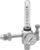
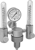
Easy-Read Tank-Mount Pressure-Regulating Valves with Flowmeter for Inert Gas
For Argon, Argon/Carbon Dioxide Blend, and Helium
Inlet | Outlet | Material | |||||||||||||||||||||||||||||||||||||||||||||||||||||||||||||||||||||||||||||||||||||||||||||||||
|---|---|---|---|---|---|---|---|---|---|---|---|---|---|---|---|---|---|---|---|---|---|---|---|---|---|---|---|---|---|---|---|---|---|---|---|---|---|---|---|---|---|---|---|---|---|---|---|---|---|---|---|---|---|---|---|---|---|---|---|---|---|---|---|---|---|---|---|---|---|---|---|---|---|---|---|---|---|---|---|---|---|---|---|---|---|---|---|---|---|---|---|---|---|---|---|---|---|---|---|
CGA No. | Location | Thread Direction | Pressure Gauge Reading Range, psi | No. of Stages | Thread Size | Location | Thread Direction | Flow Range | No. of Flowmeters | Body | Seal | Diaphragm | Each | ||||||||||||||||||||||||||||||||||||||||||||||||||||||||||||||||||||||||||||||||||||||
UNF Female Outlet × NGO Male Inlet | |||||||||||||||||||||||||||||||||||||||||||||||||||||||||||||||||||||||||||||||||||||||||||||||||||
| 580 | Side | Right Hand | 0 to 3,000 | Two | 5/8"-18 | Side | Right Hand | 0 to 40 scfh (Argon), 0 to 40 scfh (Argon/Carbon Dioxide Blend), 0 to 150 scfh (Helium) | 1 | Brass | PTFE | Neoprene | 000000000 | 0000000 | |||||||||||||||||||||||||||||||||||||||||||||||||||||||||||||||||||||||||||||||||||||
For Argon, Argon/Carbon Dioxide Blend, Carbon Dioxide, and Helium
 |
Male Inlet × Female Outlet With One Flowmeter |
Single Stage—Single-stage valves reduce pressure in one step, which causes the outlet pressure to fluctuate slightly as you empty the tank. They’re best for applications where a constant outlet pressure isn’t critical.
1 Flowmeter—Valves with one flowmeter are for one piece of equipment on a tank. The flowmeter has a single scale.
Inlet | Outlet | Material | |||||||||||||||||||||||||||||||||||||||||||||||||||||||||||||||||||||||||||||||||||||||||||||||||
|---|---|---|---|---|---|---|---|---|---|---|---|---|---|---|---|---|---|---|---|---|---|---|---|---|---|---|---|---|---|---|---|---|---|---|---|---|---|---|---|---|---|---|---|---|---|---|---|---|---|---|---|---|---|---|---|---|---|---|---|---|---|---|---|---|---|---|---|---|---|---|---|---|---|---|---|---|---|---|---|---|---|---|---|---|---|---|---|---|---|---|---|---|---|---|---|---|---|---|---|
CGA No. | Location | Thread Direction | Pressure Gauge Reading Range, psi | No. of Stages | Thread Size | Location | Thread Direction | Flow Range | No. of Flowmeters | Body | Seal | Diaphragm | Each | ||||||||||||||||||||||||||||||||||||||||||||||||||||||||||||||||||||||||||||||||||||||
UNF Female Outlet × NGO Male Inlet | |||||||||||||||||||||||||||||||||||||||||||||||||||||||||||||||||||||||||||||||||||||||||||||||||||
| 580 | Side | Right Hand | 0 to 4,000 | Single | 5/8"-18 | Side | Right Hand | 0 to 60 scfh (Argon) 0 to 60 scfh (Argon/Carbon Dioxide Blend) 0 to 50 scfh (Carbon Dioxide) 0 to 160 scfh (Helium) | 1 | Brass | Buna-N | Brass | 000000000 | 0000000 | |||||||||||||||||||||||||||||||||||||||||||||||||||||||||||||||||||||||||||||||||||||
For Argon and Helium
|  |
Male Inlet × Female Outlet With One Flowmeter | Male Inlet × Female Outlet With Two Flowmeters |
Single Stage—Single-stage valves reduce pressure in one step, which causes the outlet pressure to fluctuate slightly as you empty the tank. They’re best for applications where a constant outlet pressure isn’t critical.
Two Stage—Two-stage valves progressively reduce pressure over two steps for more consistent outlet pressure at all times. They’re often used in applications that require a constant outlet pressure regardless of the tank level.
1 Flowmeter—Valves with one flowmeter are for one piece of equipment on a tank. The flowmeter has a single scale.
2 Flowmeters—Valve with two flowmeters lets you simultaneously run two pieces of equipment from one tank. Both flowmeters have a dual scale.
Inlet | Outlet | Material | |||||||||||||||||||||||||||||||||||||||||||||||||||||||||||||||||||||||||||||||||||||||||||||||||
|---|---|---|---|---|---|---|---|---|---|---|---|---|---|---|---|---|---|---|---|---|---|---|---|---|---|---|---|---|---|---|---|---|---|---|---|---|---|---|---|---|---|---|---|---|---|---|---|---|---|---|---|---|---|---|---|---|---|---|---|---|---|---|---|---|---|---|---|---|---|---|---|---|---|---|---|---|---|---|---|---|---|---|---|---|---|---|---|---|---|---|---|---|---|---|---|---|---|---|---|
CGA No. | Location | Thread Direction | Pressure Gauge Reading Range, psi | No. of Stages | Thread Size | Location | Thread Direction | Flow Range | No. of Flowmeters | Body | Seal | Diaphragm | Each | ||||||||||||||||||||||||||||||||||||||||||||||||||||||||||||||||||||||||||||||||||||||
UNF Female Outlet × NGO Male Inlet | |||||||||||||||||||||||||||||||||||||||||||||||||||||||||||||||||||||||||||||||||||||||||||||||||||
| 580 | Side | Right Hand | 0 to 3,000 | Two | 5/8"-18 | Side | Right Hand | 0 to 18 scfh (Argon), 0 to 50 scfh (Helium) | 1 | Brass | PTFE | Neoprene | 000000000 | 0000000 | |||||||||||||||||||||||||||||||||||||||||||||||||||||||||||||||||||||||||||||||||||||
| 580 | Side | Right Hand | 0 to 3,000 | Two | 5/8"-18 | Side | Right Hand | 0 to 65 scfh (Argon), 0 to 200 scfh (Helium) | 1 | Brass | PTFE | Neoprene | 000000000 | 000000 | |||||||||||||||||||||||||||||||||||||||||||||||||||||||||||||||||||||||||||||||||||||
| 580 | Side | Right Hand | 0 to 4,000 | Single | 5/8"-18 | Side | Right Hand | 0 to 45 scfh (Argon), 0 to 140 scfh (Helium) | 1 | Brass | PTFE | Neoprene | 00000000 | 000000 | |||||||||||||||||||||||||||||||||||||||||||||||||||||||||||||||||||||||||||||||||||||
| 580 | Side | Right Hand | 0 to 4,000 | Single | 5/8"-18 | Side | Right Hand | 0 to 45 scfh (Argon), 0 to 140 scfh (Helium) | 2 | Brass | PTFE | Neoprene | 0000000 | 000000 | |||||||||||||||||||||||||||||||||||||||||||||||||||||||||||||||||||||||||||||||||||||
For Helium and Hydrogen
|
Male Inlet × Female Outlet With One Flowmeter |
Single Stage—Single-stage valves reduce pressure in one step, which causes the outlet pressure to fluctuate slightly as you empty the tank. They’re best for applications where a constant outlet pressure isn’t critical.
1 Flowmeter—Valves with one flowmeter are for one piece of equipment on a tank. The flowmeter has a single scale.
Inlet | Outlet | Material | |||||||||||||||||||||||||||||||||||||||||||||||||||||||||||||||||||||||||||||||||||||||||||||||||
|---|---|---|---|---|---|---|---|---|---|---|---|---|---|---|---|---|---|---|---|---|---|---|---|---|---|---|---|---|---|---|---|---|---|---|---|---|---|---|---|---|---|---|---|---|---|---|---|---|---|---|---|---|---|---|---|---|---|---|---|---|---|---|---|---|---|---|---|---|---|---|---|---|---|---|---|---|---|---|---|---|---|---|---|---|---|---|---|---|---|---|---|---|---|---|---|---|---|---|---|
CGA No. | Location | Thread Direction | Pressure Gauge Reading Range, psi | No. of Stages | Thread Size | Location | Thread Direction | Flow Range | No. of Flowmeters | Body | Seal | Diaphragm | Each | ||||||||||||||||||||||||||||||||||||||||||||||||||||||||||||||||||||||||||||||||||||||
UNF Female Outlet × NGO Male Inlet | |||||||||||||||||||||||||||||||||||||||||||||||||||||||||||||||||||||||||||||||||||||||||||||||||||
| 580 | Side | Right Hand | 0 to 4,000 | Single | 5/8"-18 | Side | Right Hand | 0 to 100 scfh (Helium), 0 to 140 scfh (Hydrogen) | 1 | Brass | PTFE | Neoprene | 000000000 | 0000000 | |||||||||||||||||||||||||||||||||||||||||||||||||||||||||||||||||||||||||||||||||||||
Vacuum Breakers
Straight
 |
Straights are often used with steam coils, heat exchangers, and space heaters.
303 Stainless Steel Body—303 stainless steel valves have the best corrosion resistance.
Brass Body | 303 Stainless Steel Body | ||||||||||||||||||||||||||||||||||||||||||||||||||||||||||||||||||||||||||||||||||||||||||||||||||
|---|---|---|---|---|---|---|---|---|---|---|---|---|---|---|---|---|---|---|---|---|---|---|---|---|---|---|---|---|---|---|---|---|---|---|---|---|---|---|---|---|---|---|---|---|---|---|---|---|---|---|---|---|---|---|---|---|---|---|---|---|---|---|---|---|---|---|---|---|---|---|---|---|---|---|---|---|---|---|---|---|---|---|---|---|---|---|---|---|---|---|---|---|---|---|---|---|---|---|---|
Inlet Pipe Size | Outlet Pipe SIze | Max. Pressure @ Temp. | Temp. Range, ° F | End-to-End Lg. | Seal Material | For Use With | Each | Each | |||||||||||||||||||||||||||||||||||||||||||||||||||||||||||||||||||||||||||||||||||||||||||
NPT Male Inlet × NPT Female Outlet | |||||||||||||||||||||||||||||||||||||||||||||||||||||||||||||||||||||||||||||||||||||||||||||||||||
| 1/2 | 3/8 | 300 psi @ 70° F | -20 to 365 | 1 3/4" | EPM Rubber | Air, Argon, Helium, Krypton, Neon, Steam, Water, Xenon | 0000000 | 0000000 | 0000000 | 0000000 | |||||||||||||||||||||||||||||||||||||||||||||||||||||||||||||||||||||||||||||||||||||||||
| 3/4 | 1/2 | 300 psi @ 70° F | -20 to 365 | 2 1/8" | EPM Rubber | Air, Argon, Helium, Krypton, Neon, Steam, Water, Xenon | 0000000 | 000000 | 0000000 | 000000 | |||||||||||||||||||||||||||||||||||||||||||||||||||||||||||||||||||||||||||||||||||||||||
| 1 | 3/4 | 300 psi @ 70° F | -20 to 365 | 2 3/8" | EPM Rubber | Air, Argon, Helium, Krypton, Neon, Steam, Water, Xenon | 0000000 | 000000 | 0000000 | 000000 | |||||||||||||||||||||||||||||||||||||||||||||||||||||||||||||||||||||||||||||||||||||||||
High-Pressure Vacuum Breakers
 |
Rated for 12 times the pressure of standard vacuum-breaking valves, these can handle up to 1,500 psi. Also known as vacuum-breaking valves, they have vents that open when pressure drops to relieve vacuum conditions and prevent backward suction from drawing liquid into upstream piping. Body is 316 stainless steel for excellent corrosion resistance.
Flow Coefficient (Cv)—Flow coefficient (Cv) is the amount of water (in gallons per minute) at 60° F that will flow through a fully open valve with a difference of 1 psi between the inlet and the outlet.
316 Stainless Steel Body | |||||||||||||||||||||||||||||||||||||||||||||||||||||||||||||||||||||||||||||||||||||||||||||||||||
|---|---|---|---|---|---|---|---|---|---|---|---|---|---|---|---|---|---|---|---|---|---|---|---|---|---|---|---|---|---|---|---|---|---|---|---|---|---|---|---|---|---|---|---|---|---|---|---|---|---|---|---|---|---|---|---|---|---|---|---|---|---|---|---|---|---|---|---|---|---|---|---|---|---|---|---|---|---|---|---|---|---|---|---|---|---|---|---|---|---|---|---|---|---|---|---|---|---|---|---|
Inlet Pipe Size | Outlet Pipe SIze | Flow Coefficient (Cv) | Max. Pressure @ Temp. | End-to-End Lg. | Specs. Met | Seal Material | For Use With | Temp. Range, ° F | Each | ||||||||||||||||||||||||||||||||||||||||||||||||||||||||||||||||||||||||||||||||||||||||||
NPT Female Inlet × NPT Male Outlet | |||||||||||||||||||||||||||||||||||||||||||||||||||||||||||||||||||||||||||||||||||||||||||||||||||
| 1/2 | 3/4 | 4.6 | 1,500 psi @ 70° F | 1 5/16" | ASME B1.20.1 | Fluoroelastomer | Air, Argon, Helium, Krypton, Neon, Oil, Water, Xenon | -10 to 400 | 0000000 | 0000000 | |||||||||||||||||||||||||||||||||||||||||||||||||||||||||||||||||||||||||||||||||||||||||
| 3/4 | 1 | 6.6 | 1,500 psi @ 70° F | 1 7/8" | ASME B1.20.1 | Fluoroelastomer | Air, Argon, Helium, Krypton, Neon, Oil, Water, Xenon | -10 to 400 | 0000000 | 000000 | |||||||||||||||||||||||||||||||||||||||||||||||||||||||||||||||||||||||||||||||||||||||||
