


Measure your pipe and fittings to identify their pipe size, thread size, schedule, and thread type. Then, find compatible components.


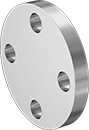
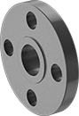
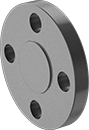
High-Pressure Stainless Steel Unthreaded Pipe Flanges
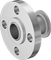 |
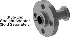
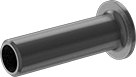
Stub End with Straight Adapter (Front) |
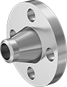 | 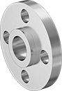 |  |
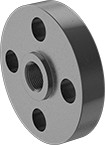
Butt Weld | Slip-On | Socket-Connect |
Pipe Size | Dash Size | Bolt Hole | 304/304L Stainless Steel | 316/316L Stainless Steel | ||||||||||||||
|---|---|---|---|---|---|---|---|---|---|---|---|---|---|---|---|---|---|---|
(A) | (B) | (A) | (B) | Flanged Connection Surface (B) | Flange OD | For Bolt Dia. | Dia. | No. Of | Bolt Circle Dia. | Pressure Class | Max. Pressure @ Temp. | Max. Steam Pressure @ Temp. | Each | Each | ||||
Butt Weld | ||||||||||||||||||
| 1/2 | 1/2 | 08 | 08 | Raised | 3 3/4" | 1/2" | 0.62" | 4 | 2 5/8" | 600 | 1,200 psi @ 72° F | 825 psi @ 400° F | ——— | 0 | 1503N31 | 000000 | ||
| 1/2 | 1/2 | 08 | 08 | Raised | 3 3/4" | 1/2" | 0.625" | 4 | 2 5/8" | 300 | 600 psi @ 72° F | 415 psi @ 360° F | 4448T286 | 000000 | 4452T296 | 00000 | ||
| 3/4 | 3/4 | 12 | 12 | Raised | 4 5/8" | 5/8" | 0.75" | 4 | 3 1/4" | 300 | 600 psi @ 72° F | 415 psi @ 360° F | 4448T287 | 00000 | 4452T297 | 00000 | ||
| 1 | 1 | 16 | 16 | Raised | 4 7/8" | 5/8" | 0.75" | 4 | 3 1/2" | 300 | 600 psi @ 72° F | 415 psi @ 360° F | 4448T288 | 00000 | 4452T298 | 00000 | ||
| 1 | 1 | 16 | 16 | Raised | 4 7/8" | 5/8" | 0.75" | 4 | 3 1/2" | 600 | 1,200 psi @ 72° F | 825 psi @ 400° F | 1538N57 | 00000 | 1503N33 | 000000 | ||
| 1 1/4 | 1 1/4 | 20 | 20 | Raised | 5 1/4" | 5/8" | 0.75" | 4 | 3 7/8" | 300 | 600 psi @ 72° F | 415 psi @ 360° F | 4448T289 | 000000 | 4452T299 | 000000 | ||
| 1 1/2 | 1 1/2 | 24 | 24 | Raised | 6 1/8" | 3/4" | 0.875" | 4 | 4 1/2" | 300 | 600 psi @ 72° F | 415 psi @ 360° F | 4448T291 | 000000 | 4452T311 | 000000 | ||
| 1 1/2 | 1 1/2 | 24 | 24 | Raised | 6 1/8" | 3/4" | 0.875" | 4 | 4 1/2" | 600 | 1,200 psi @ 72° F | 825 psi @ 400° F | 1538N59 | 000000 | 1503N35 | 000000 | ||
| 2 | 2 | 32 | 32 | Raised | 6 1/2" | 5/8" | 0.75" | 8 | 5" | 300 | 600 psi @ 72° F | 415 psi @ 360° F | 4448T292 | 000000 | 4452T312 | 000000 | ||
| 2 | 2 | 32 | 32 | Raised | 6 1/2" | 5/8" | 0.75" | 8 | 5" | 600 | 1,200 psi @ 72° F | 825 psi @ 400° F | 1538N61 | 000000 | 1503N36 | 000000 | ||
| 2 1/2 | 2 1/2 | 40 | 40 | Raised | 7 1/2" | 3/4" | 0.875" | 8 | 5 7/8" | 300 | 600 psi @ 72° F | 415 psi @ 360° F | 4448T293 | 000000 | 4452T313 | 000000 | ||
| 3 | 3 | 48 | 48 | Raised | 8 1/4" | 3/4" | 0.875" | 8 | 6 5/8" | 300 | 600 psi @ 72° F | 415 psi @ 360° F | 4448T294 | 000000 | 4452T314 | 000000 | ||
| 3 | 3 | 48 | 48 | Raised | 8 1/4" | 3/4" | 0.88" | 8 | 6 5/8" | 600 | 1,200 psi @ 72° F | 825 psi @ 400° F | ——— | 0 | 1503N38 | 000000 | ||
| 4 | 4 | 64 | 64 | Raised | 10" | 3/4" | 0.875" | 8 | 7 7/8" | 300 | 600 psi @ 72° F | 415 psi @ 360° F | 4448T295 | 000000 | 4452T315 | 000000 | ||
| 4 | 4 | 64 | 64 | Raised | 10 3/4" | 7/8" | 1" | 8 | 8 1/2" | 600 | 1,200 psi @ 72° F | 825 psi @ 400° F | 1538N64 | 000000 | ——— | 0 | ||
| 6 | 6 | 96 | 96 | Raised | 12 1/2" | 3/4" | 0.875" | 12 | 10 5/8" | 300 | 600 psi @ 72° F | 415 psi @ 360° F | 4448T296 | 000000 | 4452T316 | 000000 | ||
Slip-On Weld Female | ||||||||||||||||||
| 1/2 | 1/2 | 08 | 08 | Raised | 3 3/4" | 1/2" | 0.625" | 4 | 2 5/8" | 300 | 600 psi @ 72° F | 300 psi @ 360° F | 4448T251 | 00000 | 4452T261 | 00000 | ||
| 3/4 | 3/4 | 12 | 12 | Raised | 4 5/8" | 5/8" | 0.75" | 4 | 3 1/4" | 300 | 600 psi @ 72° F | 300 psi @ 360° F | 4448T252 | 00000 | 4452T262 | 00000 | ||
| 3/4 | 3/4 | 12 | 12 | Raised | 4 5/8" | 5/8" | 0.75" | 4 | 3 1/4" | 600 | 1,200 psi @ 72° F | 840 psi @ 400° F | ——— | 0 | 1503N12 | 00000 | ||
| 1 | 1 | 16 | 16 | Raised | 4 7/8" | 5/8" | 0.75" | 4 | 3 1/2" | 300 | 600 psi @ 72° F | 300 psi @ 360° F | 4448T253 | 00000 | 4452T263 | 00000 | ||
| 1 | 1 | 16 | 16 | Raised | 4 7/8" | 5/8" | 0.75" | 4 | 3 1/2" | 600 | 1,200 psi @ 72° F | 840 psi @ 400° F | 1538N17 | 00000 | 1503N13 | 00000 | ||
| 1 1/4 | 1 1/4 | 20 | 20 | Raised | 5 1/4" | 5/8" | 0.75" | 4 | 3 7/8" | 300 | 600 psi @ 72° F | 300 psi @ 360° F | 4448T254 | 00000 | 4452T264 | 000000 | ||
| 1 1/2 | 1 1/2 | 24 | 24 | Raised | 6 1/8" | 3/4" | 0.875" | 4 | 4 1/2" | 300 | 600 psi @ 72° F | 300 psi @ 360° F | 4448T255 | 000000 | 4452T265 | 000000 | ||
| 1 1/2 | 1 1/2 | 24 | 24 | Raised | 6 1/8" | 3/4" | 0.875" | 4 | 4 1/2" | 600 | 1,200 psi @ 72° F | 840 psi @ 400° F | 1538N19 | 000000 | ——— | 0 | ||
| 2 | 2 | 32 | 32 | Raised | 6 1/2" | 5/8" | 0.75" | 8 | 5" | 300 | 600 psi @ 72° F | 300 psi @ 360° F | 4448T256 | 000000 | 4452T266 | 000000 | ||
| 2 | 2 | 32 | 32 | Raised | 6 1/2" | 5/8" | 0.75" | 8 | 5" | 600 | 1,200 psi @ 72° F | 840 psi @ 400° F | 1538N21 | 000000 | 1503N16 | 000000 | ||
| 2 1/2 | 2 1/2 | 40 | 40 | Raised | 7 1/2" | 3/4" | 0.875" | 8 | 5 7/8" | 300 | 600 psi @ 72° F | 300 psi @ 360° F | 4448T257 | 000000 | 4452T267 | 000000 | ||
| 3 | 3 | 48 | 48 | Raised | 8 1/4" | 3/4" | 0.875" | 8 | 6 5/8" | 300 | 600 psi @ 72° F | 300 psi @ 360° F | 4448T258 | 000000 | 4452T268 | 000000 | ||
| 3 | 3 | 48 | 48 | Raised | 8 1/4" | 3/4" | 0.88" | 8 | 6 5/8" | 600 | 1,200 psi @ 72° F | 840 psi @ 400° F | 1538N23 | 000000 | ——— | 0 | ||
| 4 | 4 | 64 | 64 | Raised | 10" | 3/4" | 0.875" | 8 | 7 7/8" | 300 | 600 psi @ 72° F | 300 psi @ 360° F | 4448T259 | 000000 | 4452T269 | 000000 | ||
| 4 | 4 | 64 | 64 | Raised | 10 3/4" | 7/8" | 1" | 8 | 8 1/2" | 600 | 1,200 psi @ 72° F | 840 psi @ 400° F | 1538N24 | 000000 | ——— | 0 | ||
| 6 | 6 | 96 | 96 | Raised | 12 1/2" | 3/4" | 0.875" | 12 | 10 5/8" | 300 | 600 psi @ 72° F | 300 psi @ 360° F | 4448T261 | 000000 | 4452T271 | 000000 | ||
| 8 | 8 | — | — | Raised | 15" | 7/8" | 1" | 12 | 13" | 300 | 600 psi @ 72° F | 300 psi @ 360° F | 4448T43 | 000000 | ——— | 0 | ||
Socket-Connect Female | ||||||||||||||||||
| 1/2 | 1/2 | 08 | 08 | Raised | 3 3/4" | 1/2" | 0.62" | 4 | 2 5/8" | 600 | 1,200 psi @ 72° F | 840 psi @ 400° F | ——— | 0 | 1503N21 | 00000 | ||
| 1/2 | 1/2 | 08 | 08 | Raised | 3 3/4" | 1/2" | 0.625" | 4 | 2 5/8" | 300 | 600 psi @ 72° F | 300 psi @ 360° F | 4448T264 | 00000 | 4452T274 | 00000 | ||
| 3/4 | 3/4 | 12 | 12 | Raised | 4 5/8" | 5/8" | 0.75" | 4 | 3 1/4" | 300 | 600 psi @ 72° F | 300 psi @ 360° F | 4448T265 | 00000 | 4452T275 | 00000 | ||
| 3/4 | 3/4 | 12 | 12 | Raised | 4 5/8" | 5/8" | 0.75" | 4 | 3 1/4" | 600 | 1,200 psi @ 72° F | 840 psi @ 400° F | ——— | 0 | 1503N22 | 00000 | ||
| 1 | 1 | 16 | 16 | Raised | 4 7/8" | 5/8" | 0.75" | 4 | 3 1/2" | 300 | 600 psi @ 72° F | 300 psi @ 360° F | 4448T266 | 00000 | 4452T276 | 00000 | ||
| 1 | 1 | 16 | 16 | Raised | 4 7/8" | 5/8" | 0.75" | 4 | 3 1/2" | 600 | 1,200 psi @ 72° F | 840 psi @ 400° F | 1538N37 | 00000 | 1503N23 | 000000 | ||
| 1 1/4 | 1 1/4 | 20 | 20 | Raised | 5 1/4" | 5/8" | 0.75" | 4 | 3 7/8" | 300 | 600 psi @ 72° F | 300 psi @ 360° F | 4448T267 | 000000 | 4452T277 | 000000 | ||
| 1 1/2 | 1 1/2 | 24 | 24 | Raised | 6 1/8" | 3/4" | 0.875" | 4 | 4 1/2" | 300 | 600 psi @ 72° F | 300 psi @ 360° F | 4448T268 | 00000 | 4452T278 | 000000 | ||
| 1 1/2 | 1 1/2 | 24 | 24 | Raised | 6 1/8" | 3/4" | 0.875" | 4 | 4 1/2" | 600 | 1,200 psi @ 72° F | 840 psi @ 400° F | 1538N39 | 000000 | 1503N25 | 000000 | ||
| 2 | 2 | 32 | 32 | Raised | 6 1/2" | 5/8" | 0.75" | 8 | 5" | 300 | 600 psi @ 72° F | 300 psi @ 360° F | 4448T269 | 000000 | 4452T279 | 000000 | ||
| 2 | 2 | 32 | 32 | Raised | 6 1/2" | 5/8" | 0.75" | 8 | 5" | 600 | 1,200 psi @ 72° F | 840 psi @ 400° F | 1538N41 | 000000 | 1503N26 | 000000 | ||
| 2 1/2 | 2 1/2 | 40 | 40 | Raised | 7 1/2" | 3/4" | 0.875" | 8 | 5 7/8" | 300 | 600 psi @ 72° F | 300 psi @ 360° F | 4448T271 | 000000 | ——— | 0 | ||
| 3 | 3 | 48 | 48 | Raised | 8 1/4" | 3/4" | 0.875" | 8 | 6 5/8" | 300 | 600 psi @ 72° F | 300 psi @ 360° F | 4448T272 | 000000 | 4452T282 | 000000 | ||
| 3 | 3 | 48 | 48 | Raised | 8 1/4" | 3/4" | 0.88" | 8 | 6 5/8" | 600 | 1,200 psi @ 72° F | 840 psi @ 400° F | 1538N43 | 000000 | ——— | 0 | ||
| 4 | 4 | 64 | 64 | Raised | 10" | 3/4" | 0.875" | 8 | 7 7/8" | 300 | 600 psi @ 72° F | 300 psi @ 360° F | 4448T273 | 000000 | 4452T283 | 000000 | ||
| 6 | 6 | 96 | 96 | Raised | 12 1/2" | 3/4" | 0.875" | 12 | 10 5/8" | 300 | 600 psi @ 72° F | 300 psi @ 360° F | 4448T274 | 000000 | ——— | 0 | ||
Stub End | ||||||||||||||||||
| 3/4 | 3/4 | 12 | 12 | Flat | 4 5/8" | 5/8" | 0.75" | 4 | 3 1/4" | 300 | 600 psi @ 72° F | 300 psi @ 360° F | 4448T298 | 00000 | ——— | 0 | ||
| 1 | 1 | 16 | 16 | Flat | 4 7/8" | 5/8" | 0.75" | 4 | 3 1/2" | 300 | 600 psi @ 72° F | 300 psi @ 360° F | 4448T299 | 00000 | 4452T319 | 00000 | ||
| 1 | 1 | 16 | 16 | Flat | 4 7/8" | 5/8" | 0.75" | 4 | 3 1/2" | 600 | 1,200 psi @ 72° F | 840 psi @ 400° F | 1538N77 | 00000 | ——— | 0 | ||
| 1 1/2 | 1 1/2 | 24 | 24 | Flat | 6 1/8" | 3/4" | 0.875" | 4 | 4 1/2" | 300 | 600 psi @ 72° F | 300 psi @ 360° F | 4448T312 | 000000 | 4452T322 | 000000 | ||
| 2 | 2 | 32 | 32 | Flat | 6 1/2" | 5/8" | 0.75" | 8 | 5" | 300 | 600 psi @ 72° F | 300 psi @ 360° F | 4448T313 | 000000 | 4452T323 | 000000 | ||
| 2 1/2 | 2 1/2 | 40 | 40 | Flat | 7 1/2" | 3/4" | 0.875" | 8 | 5 7/8" | 300 | 600 psi @ 72° F | 300 psi @ 360° F | 4448T314 | 000000 | 4452T324 | 000000 | ||
| 3 | 3 | 48 | 48 | Flat | 8 1/4" | 3/4" | 0.875" | 8 | 6 5/8" | 300 | 600 psi @ 72° F | 300 psi @ 360° F | 4448T315 | 000000 | 4452T325 | 000000 | ||
| 4 | 4 | 64 | 64 | Flat | 10" | 3/4" | 0.875" | 8 | 7 7/8" | 300 | 600 psi @ 72° F | 300 psi @ 360° F | 4448T262 | 000000 | ——— | 0 | ||
| 4 | 4 | 64 | 64 | Flat | 10 3/4" | 7/8" | 1" | 8 | 8 1/2" | 600 | 1,200 psi @ 72° F | 840 psi @ 400° F | 1538N84 | 000000 | ——— | 0 | ||
| 6 | 6 | 96 | 96 | Flat | 12 1/2" | 3/4" | 0.875" | 12 | 10 5/8" | 300 | 600 psi @ 72° F | 300 psi @ 360° F | 4448T263 | 000000 | ——— | 0 | ||
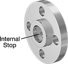
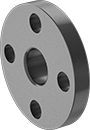
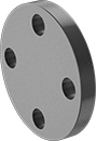
 | 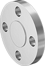 |
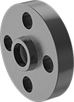
Front | Raised Surface on Back |
Bolt Hole | 304/304L Stainless Steel | 316/316L Stainless Steel | ||||||||||||||
|---|---|---|---|---|---|---|---|---|---|---|---|---|---|---|---|---|
Pipe Size | Dash Size | Flanged Connection Surface | Flange OD | For Bolt Dia. | Dia. | No. Of | Bolt Circle Dia. | Pressure Class | Max. Pressure @ Temp. | Max. Steam Pressure @ Temp. | Each | Each | ||||
Flanged | ||||||||||||||||
| 1/2 | 08 | Raised | 3 3/4" | 1/2" | 0.62" | 4 | 2 5/8" | 600 | 1,200 psi @ 72° F | 840 psi @ 400° F | 1538N91 | 000000 | 1503N51 | 000000 | ||
| 1/2 | 08 | Raised | 3 3/4" | 1/2" | 0.625" | 4 | 2 5/8" | 300 | 600 psi @ 72° F | 300 psi @ 360° F | 4448T275 | 00000 | 4452T285 | 00000 | ||
| 3/4 | 12 | Raised | 4 5/8" | 5/8" | 0.75" | 4 | 3 1/4" | 300 | 600 psi @ 72° F | 300 psi @ 360° F | 4448T276 | 00000 | 4452T286 | 00000 | ||
| 3/4 | 12 | Raised | 4 5/8" | 5/8" | 0.75" | 4 | 3 1/4" | 600 | 1,200 psi @ 72° F | 840 psi @ 400° F | 1538N92 | 00000 | ——— | 0 | ||
| 1 | 16 | Raised | 4 7/8" | 5/8" | 0.75" | 4 | 3 1/2" | 300 | 600 psi @ 72° F | 300 psi @ 360° F | 4448T277 | 00000 | 4452T287 | 00000 | ||
| 1 | 16 | Raised | 4 7/8" | 5/8" | 0.75" | 4 | 3 1/2" | 600 | 1,200 psi @ 72° F | 840 psi @ 400° F | 1538N93 | 00000 | 1503N53 | 000000 | ||
| 1 1/4 | 20 | Raised | 5 1/4" | 5/8" | 0.75" | 4 | 3 7/8" | 300 | 600 psi @ 72° F | 300 psi @ 360° F | 4448T278 | 00000 | 4452T288 | 000000 | ||
| 1 1/4 | 20 | Raised | 5 1/4" | 5/8" | 0.75" | 4 | 3 7/8" | 600 | 1,200 psi @ 72° F | 840 psi @ 400° F | 1538N94 | 000000 | ——— | 0 | ||
| 1 1/2 | 24 | Raised | 6 1/8" | 3/4" | 0.875" | 4 | 4 1/2" | 300 | 600 psi @ 72° F | 300 psi @ 360° F | 4448T279 | 000000 | 4452T289 | 000000 | ||
| 1 1/2 | 24 | Raised | 6 1/8" | 3/4" | 0.875" | 4 | 4 1/2" | 600 | 1,200 psi @ 72° F | 840 psi @ 400° F | 1538N95 | 000000 | 1503N55 | 000000 | ||
| 2 | 32 | Raised | 6 1/2" | 5/8" | 0.75" | 8 | 5" | 300 | 600 psi @ 72° F | 300 psi @ 360° F | 4448T281 | 000000 | 4452T291 | 000000 | ||
| 2 | 32 | Raised | 6 1/2" | 5/8" | 0.75" | 8 | 5" | 600 | 1,200 psi @ 72° F | 840 psi @ 400° F | 1538N96 | 000000 | 1503N56 | 000000 | ||
| 2 1/2 | 40 | Raised | 7 1/2" | 3/4" | 0.875" | 8 | 5 7/8" | 300 | 600 psi @ 72° F | 300 psi @ 360° F | 4448T282 | 000000 | 4452T292 | 000000 | ||
| 2 1/2 | 40 | Raised | 7 1/2" | 3/4" | 0.88" | 8 | 5 7/8" | 600 | 1,200 psi @ 72° F | 840 psi @ 400° F | 1538N97 | 000000 | 1503N57 | 000000 | ||
| 3 | 48 | Raised | 8 1/4" | 3/4" | 0.875" | 8 | 6 5/8" | 300 | 600 psi @ 72° F | 300 psi @ 360° F | 4448T283 | 000000 | 4452T293 | 000000 | ||
| 3 | 48 | Raised | 8 1/4" | 3/4" | 0.88" | 8 | 6 5/8" | 600 | 1,200 psi @ 72° F | 840 psi @ 400° F | 1538N98 | 000000 | 1503N58 | 000000 | ||
| 4 | 64 | Raised | 10" | 3/4" | 0.875" | 8 | 7 7/8" | 300 | 600 psi @ 72° F | 300 psi @ 360° F | 4448T284 | 000000 | 4452T294 | 000000 | ||
| 4 | 64 | Raised | 10 3/4" | 7/8" | 1" | 8 | 8 1/2" | 600 | 1,200 psi @ 72° F | 840 psi @ 400° F | 1538N99 | 000000 | 1503N59 | 000000 | ||
| 6 | 96 | Raised | 12 1/2" | 3/4" | 0.875" | 12 | 10 5/8" | 300 | 600 psi @ 72° F | 300 psi @ 360° F | 4448T285 | 000000 | 4452T295 | 000000 | ||
| 8 | — | Raised | 15" | 7/8" | 1" | 12 | 13" | 300 | 600 psi @ 72° F | 300 psi @ 360° F | 4448T48 | 000000 | 4452T116 | 000000 | ||
| 10 | — | Raised | 17 1/2" | 1" | 1.12" | 16 | 15 1/4" | 300 | 600 psi @ 72° F | 300 psi @ 360° F | 4448T49 | 000000 | ——— | 0 | ||
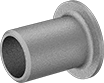 |
Straight Adapter |
304/304L Stainless Steel | 316/316L Stainless Steel | ||||||||
|---|---|---|---|---|---|---|---|---|---|
Pipe Size | Wall Thk. | Flange OD | Construction | Pipe Schedule | Each | Each | |||
| 3/4 | 0.113" | 1 11/16" | Welded | 40 | 45605K652 | 000000 | ——— | 0 | |
| 1 | 0.133" | 2" | Welded | 40 | 45605K653 | 00000 | 45555K653 | 000000 | |
| 1 1/2 | 0.145" | 2 7/8" | Welded | 40 | 45605K655 | 00000 | 45555K655 | 00000 | |
| 2 | 0.154" | 3 5/8" | Welded | 40 | 45605K656 | 00000 | 45555K656 | 00000 | |
| 2 1/2 | 0.203" | 4 1/8" | Welded | 40 | 45605K657 | 00000 | 45555K657 | 00000 | |
| 3 | 0.216" | 5" | Welded | 40 | 45605K661 | 00000 | 45555K661 | 00000 | |
| 4 | 0.237" | 6 3/16" | Welded | 40 | 45605K663 | 00000 | ——— | 0 | |
| 6 | 0.28" | 8 1/2" | Welded | 40 | 45605K665 | 000000 | ——— | 0 | |
High-Pressure Iron and Steel Unthreaded Pipe Flanges
 |  | 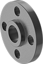 |  |
Butt Weld (Front) | Butt Weld (Raised Surface on Back) | Slip-On Weld (Front) | Slip-On Weld (Raised Surface on Back) |
 |  |  |  |
Socket Connect (Front) | Socket-Connect (Raised Surface on Back) | Stub-End (Front) | Stub-End (Flat Surface on Back) |
Pipe Size | Dash Size | Bolt Hole | |||||||||||||||
|---|---|---|---|---|---|---|---|---|---|---|---|---|---|---|---|---|---|
(A) | (B) | (A) | (B) | Flanged Connection Surface (B) | Flange OD | For Bolt Dia. | Dia. | No. Of | Bolt Circle Dia. | Pressure Class | Material | Max. Pressure @ Temp. | Max. Steam Pressure @ Temp. | Each | |||
Butt Weld | |||||||||||||||||
| 1/2 | 1/2 | 08 | 08 | Raised | 3 3/4" | 1/2" | 5/8" | 4 | 2 5/8" | 300 | Steel | 600 psi @ 72° F | 300 psi @ 300° F | 6806K346 | 000000 | ||
| 3/4 | 3/4 | 12 | 12 | Raised | 4 5/8" | 5/8" | 3/4" | 4 | 3 1/4" | 300 | Steel | 600 psi @ 72° F | 300 psi @ 300° F | 6806K297 | 00000 | ||
| 1 | 1 | 16 | 16 | Raised | 4 7/8" | 5/8" | 3/4" | 4 | 3 1/2" | 300 | Steel | 600 psi @ 72° F | 300 psi @ 300° F | 6806K298 | 00000 | ||
| 1 | 1 | 16 | 16 | Raised | 4.88" | 3/4" | 3/4" | 4 | 3 1/2" | 600 | Steel | 1,400 psi @ 72° F | 1,300 psi @ 300° F | 6806K448 | 00000 | ||
| 1 1/4 | 1 1/4 | 20 | 20 | Raised | 5 1/4" | 5/8" | 3/4" | 4 | 3 7/8" | 300 | Steel | 600 psi @ 72° F | 300 psi @ 300° F | 6806K299 | 00000 | ||
| 1 1/2 | 1 1/2 | 24 | 24 | Raised | 6 1/8" | 3/4" | 7/8" | 4 | 4 1/2" | 300 | Steel | 600 psi @ 72° F | 300 psi @ 300° F | 6806K311 | 00000 | ||
| 2 | 2 | 32 | 32 | Raised | 6 1/2" | 5/8" | 3/4" | 8 | 5" | 300 | Steel | 600 psi @ 72° F | 300 psi @ 300° F | 6806K312 | 00000 | ||
| 2 | 2 | 32 | 32 | Raised | 6 1/2" | 3/4" | 3/4" | 8 | 5" | 600 | Steel | 1,400 psi @ 72° F | 1,300 psi @ 300° F | 6806K451 | 00000 | ||
| 2 1/2 | 2 1/2 | 40 | 40 | Raised | 7 1/2" | 3/4" | 7/8" | 8 | 5 7/8" | 300 | Steel | 600 psi @ 72° F | 300 psi @ 300° F | 6806K313 | 00000 | ||
| 3 | 3 | 48 | 48 | Raised | 8 1/4" | 3/4" | 7/8" | 8 | 6 5/8" | 300 | Steel | 600 psi @ 72° F | 300 psi @ 300° F | 6806K314 | 00000 | ||
| 3 | 3 | 48 | 48 | Raised | 8 1/4" | 0.88" | 0.88" | 8 | 6.62" | 600 | Steel | 1,400 psi @ 72° F | 1,300 psi @ 300° F | 6806K452 | 00000 | ||
| 4 | 4 | 64 | 64 | Raised | 10" | 3/4" | 7/8" | 8 | 7 7/8" | 300 | Steel | 600 psi @ 72° F | 300 psi @ 300° F | 6806K315 | 00000 | ||
| 4 | 4 | 64 | 64 | Raised | 10 3/4" | 1" | 1" | 8 | 8 1/2" | 600 | Steel | 1,400 psi @ 72° F | 1,300 psi @ 300° F | 6806K453 | 000000 | ||
| 5 | 5 | — | — | Raised | 11" | 3/4" | 7/8" | 8 | 9 1/4" | 300 | Steel | 600 psi @ 72° F | 300 psi @ 300° F | 6806K344 | 000000 | ||
| 6 | 6 | 96 | 96 | Raised | 12 1/2" | 3/4" | 7/8" | 12 | 10 5/8" | 300 | Steel | 600 psi @ 72° F | 300 psi @ 300° F | 6806K316 | 000000 | ||
| 8 | 8 | — | — | Raised | 15" | 7/8" | 1" | 12 | 13" | 300 | Steel | 600 psi @ 72° F | 300 psi @ 300° F | 6806K345 | 000000 | ||
Slip-On Weld Female | |||||||||||||||||
| 1/2 | 1/2 | 08 | 08 | Raised | 3 3/4" | 1/2" | 5/8" | 4 | 2 5/8" | 300 | Steel | 600 psi @ 72° F | 300 psi @ 300° F | 6806K339 | 00000 | ||
| 3/4 | 3/4 | 12 | 12 | Raised | 4 5/8" | 5/8" | 3/4" | 4 | 3 1/4" | 300 | Steel | 600 psi @ 72° F | 300 psi @ 300° F | 6806K277 | 00000 | ||
| 1 | 1 | 16 | 16 | Raised | 4 7/8" | 5/8" | 3/4" | 4 | 3 1/2" | 300 | Steel | 600 psi @ 72° F | 300 psi @ 300° F | 6806K278 | 00000 | ||
| 1 | 1 | 16 | 16 | Raised | 4.88" | 3/4" | 3/4" | 4 | 3 1/2" | 600 | Steel | 1,400 psi @ 72° F | 1,300 psi @ 300° F | 6806K435 | 00000 | ||
| 1 1/4 | 1 1/4 | 20 | 20 | Raised | 5 1/4" | 5/8" | 3/4" | 4 | 3 7/8" | 300 | Steel | 600 psi @ 72° F | 300 psi @ 300° F | 6806K279 | 00000 | ||
| 1 1/2 | 1 1/2 | 24 | 24 | Raised | 6.12" | 0.88" | 0.88" | 4 | 4 1/2" | 600 | Steel | 1,400 psi @ 72° F | 1,300 psi @ 300° F | 6806K436 | 00000 | ||
| 1 1/2 | 1 1/2 | 24 | 24 | Raised | 6 1/8" | 3/4" | 7/8" | 4 | 4 1/2" | 300 | Steel | 600 psi @ 72° F | 300 psi @ 300° F | 6806K281 | 00000 | ||
| 2 | 2 | 32 | 32 | Raised | 6 1/2" | 5/8" | 3/4" | 8 | 5" | 300 | Steel | 600 psi @ 72° F | 300 psi @ 300° F | 6806K282 | 00000 | ||
| 2 | 2 | 32 | 32 | Raised | 6 1/2" | 3/4" | 3/4" | 8 | 5" | 600 | Steel | 1,400 psi @ 72° F | 1,300 psi @ 300° F | 6806K437 | 00000 | ||
| 2 1/2 | 2 1/2 | 40 | 40 | Raised | 7 1/2" | 3/4" | 7/8" | 8 | 5 7/8" | 300 | Steel | 600 psi @ 72° F | 300 psi @ 300° F | 6806K283 | 00000 | ||
| 3 | 3 | 48 | 48 | Raised | 8 1/4" | 3/4" | 7/8" | 8 | 6 5/8" | 300 | Steel | 600 psi @ 72° F | 300 psi @ 300° F | 6806K284 | 00000 | ||
| 3 | 3 | 48 | 48 | Raised | 8 1/4" | 0.88" | 0.88" | 8 | 6.62" | 600 | Steel | 1,400 psi @ 72° F | 1,300 psi @ 300° F | 6806K438 | 00000 | ||
| 4 | 4 | 64 | 64 | Raised | 10" | 3/4" | 7/8" | 8 | 7 7/8" | 300 | Steel | 600 psi @ 72° F | 300 psi @ 300° F | 6806K285 | 00000 | ||
| 4 | 4 | 64 | 64 | Raised | 10 3/4" | 1" | 1" | 8 | 8 1/2" | 600 | Steel | 1,400 psi @ 72° F | 1,300 psi @ 300° F | 6806K439 | 000000 | ||
| 5 | 5 | — | — | Raised | 11" | 3/4" | 7/8" | 8 | 9 1/4" | 300 | Steel | 600 psi @ 72° F | 300 psi @ 300° F | 6806K337 | 000000 | ||
| 6 | 6 | 96 | 96 | Raised | 12 1/2" | 3/4" | 7/8" | 12 | 10 5/8" | 300 | Steel | 600 psi @ 72° F | 300 psi @ 300° F | 6806K286 | 000000 | ||
| 6 | 6 | 96 | 96 | Raised | 14" | 1.12" | 1.12" | 12 | 11 1/2" | 600 | Steel | 1,400 psi @ 72° F | 1,300 psi @ 300° F | 6806K441 | 000000 | ||
| 8 | 8 | — | — | Raised | 15" | 7/8" | 1" | 12 | 13" | 300 | Steel | 600 psi @ 72° F | 300 psi @ 300° F | 6806K338 | 000000 | ||
| 10 | 10 | — | — | Raised | 17 1/2" | 1.12" | 1.12" | 16 | 15 1/4" | 300 | Steel | 600 psi @ 72° F | 300 psi @ 300° F | 6806K413 | 000000 | ||
| 12 | 12 | — | — | Raised | 20 1/2" | 1 1/4" | 1 1/4" | 16 | 17 3/4" | 300 | Steel | 600 psi @ 72° F | 300 psi @ 300° F | 6806K414 | 000000 | ||
Socket-Connect Female | |||||||||||||||||
| 1/2 | 1/2 | 08 | 08 | Raised | 3 3/4" | 1/2" | 5/8" | 4 | 2 5/8" | 300 | Steel | 600 psi @ 72° F | 300 psi @ 300° F | 6806K343 | 00000 | ||
| 3/4 | 3/4 | 12 | 12 | Raised | 4 5/8" | 5/8" | 3/4" | 4 | 3 1/4" | 300 | Steel | 600 psi @ 72° F | 300 psi @ 300° F | 6806K287 | 00000 | ||
| 1 | 1 | 16 | 16 | Raised | 4 7/8" | 5/8" | 3/4" | 4 | 3 1/2" | 300 | Steel | 600 psi @ 72° F | 300 psi @ 300° F | 6806K288 | 00000 | ||
| 1 | 1 | 16 | 16 | Raised | 4.88" | 3/4" | 3/4" | 4 | 3 1/2" | 600 | Steel | 1,400 psi @ 72° F | 1,300 psi @ 300° F | 6806K428 | 00000 | ||
| 1 1/4 | 1 1/4 | 20 | 20 | Raised | 5 1/4" | 5/8" | 3/4" | 4 | 3 7/8" | 300 | Steel | 600 psi @ 72° F | 300 psi @ 300° F | 6806K289 | 00000 | ||
| 1 1/2 | 1 1/2 | 24 | 24 | Raised | 6.12" | 0.88" | 0.88" | 4 | 4 1/2" | 600 | Steel | 1,400 psi @ 72° F | 1,300 psi @ 300° F | 6806K429 | 00000 | ||
| 1 1/2 | 1 1/2 | 24 | 24 | Raised | 6 1/8" | 3/4" | 7/8" | 4 | 4 1/2" | 300 | Steel | 600 psi @ 72° F | 300 psi @ 300° F | 6806K291 | 00000 | ||
| 2 | 2 | 32 | 32 | Raised | 6 1/2" | 5/8" | 3/4" | 8 | 5" | 300 | Steel | 600 psi @ 72° F | 300 psi @ 300° F | 6806K292 | 00000 | ||
| 2 | 2 | 32 | 32 | Raised | 6 1/2" | 3/4" | 3/4" | 8 | 5" | 600 | Steel | 1,400 psi @ 72° F | 1,300 psi @ 300° F | 6806K431 | 00000 | ||
| 2 1/2 | 2 1/2 | 40 | 40 | Raised | 7 1/2" | 3/4" | 7/8" | 8 | 5 7/8" | 300 | Steel | 600 psi @ 72° F | 300 psi @ 300° F | 6806K293 | 00000 | ||
| 3 | 3 | 48 | 48 | Raised | 8 1/4" | 3/4" | 7/8" | 8 | 6 5/8" | 300 | Steel | 600 psi @ 72° F | 300 psi @ 300° F | 6806K294 | 00000 | ||
| 3 | 3 | 48 | 48 | Raised | 8 1/4" | 0.88" | 0.88" | 8 | 6.62" | 600 | Steel | 1,400 psi @ 72° F | 1,300 psi @ 300° F | 6806K432 | 00000 | ||
| 4 | 4 | 64 | 64 | Raised | 10" | 3/4" | 7/8" | 8 | 7 7/8" | 300 | Steel | Not Rated | Not Rated | 6806K295 | 000000 | ||
| 4 | 4 | 64 | 64 | Raised | 10 3/4" | 1" | 1" | 8 | 8 1/2" | 600 | Steel | Not Rated | Not Rated | 6806K433 | 000000 | ||
| 5 | 5 | — | — | Raised | 11" | 3/4" | 7/8" | 8 | 9 1/4" | 300 | Steel | Not Rated | Not Rated | 6806K341 | 000000 | ||
| 6 | 6 | 96 | 96 | Raised | 12 1/2" | 3/4" | 7/8" | 12 | 10 5/8" | 300 | Steel | Not Rated | Not Rated | 6806K296 | 000000 | ||
| 8 | 8 | — | — | Raised | 15" | 7/8" | 1" | 12 | 13" | 300 | Steel | Not Rated | Not Rated | 6806K342 | 000000 | ||
Stub-End Female | |||||||||||||||||
| 1/2 | 1/2 | 08 | 08 | Flat | 3 3/4" | 1/2" | 5/8" | 4 | 2 5/8" | 300 | Steel | 600 psi @ 72° F | 300 psi @ 300° F | 6806K353 | 00000 | ||
| 3/4 | 3/4 | 12 | 12 | Flat | 4 5/8" | 5/8" | 3/4" | 4 | 3 1/4" | 300 | Steel | 600 psi @ 72° F | 300 psi @ 300° F | 6806K327 | 00000 | ||
| 1 | 1 | 16 | 16 | Flat | 4 7/8" | 5/8" | 3/4" | 4 | 3 1/2" | 300 | Steel | 600 psi @ 72° F | 300 psi @ 300° F | 6806K328 | 00000 | ||
| 1 1/4 | 1 1/4 | 20 | 20 | Flat | 5 1/4" | 5/8" | 3/4" | 4 | 3 7/8" | 300 | Steel | 600 psi @ 72° F | 300 psi @ 300° F | 6806K329 | 00000 | ||
| 1 1/2 | 1 1/2 | 24 | 24 | Flat | 6 1/8" | 3/4" | 7/8" | 4 | 4 1/2" | 300 | Steel | 600 psi @ 72° F | 300 psi @ 300° F | 6806K331 | 00000 | ||
| 2 | 2 | 32 | 32 | Flat | 6 1/2" | 5/8" | 3/4" | 8 | 5" | 300 | Steel | 600 psi @ 72° F | 300 psi @ 300° F | 6806K332 | 00000 | ||
| 2 1/2 | 2 1/2 | 40 | 40 | Flat | 7 1/2" | 3/4" | 7/8" | 8 | 5 7/8" | 300 | Steel | 600 psi @ 72° F | 300 psi @ 300° F | 6806K333 | 00000 | ||
| 3 | 3 | 48 | 48 | Flat | 8 1/4" | 3/4" | 7/8" | 8 | 6 5/8" | 300 | Steel | 600 psi @ 72° F | 300 psi @ 300° F | 6806K334 | 00000 | ||
| 4 | 4 | 64 | 64 | Flat | 10" | 3/4" | 7/8" | 8 | 7 7/8" | 300 | Steel | 600 psi @ 72° F | 300 psi @ 300° F | 6806K335 | 00000 | ||
| 5 | 5 | — | — | Flat | 11" | 3/4" | 7/8" | 8 | 9 1/4" | 300 | Steel | 600 psi @ 72° F | 300 psi @ 300° F | 6806K351 | 000000 | ||
| 6 | 6 | 96 | 96 | Flat | 12 1/2" | 3/4" | 7/8" | 12 | 10 5/8" | 300 | Steel | 600 psi @ 72° F | 300 psi @ 300° F | 6806K336 | 000000 | ||
| 8 | 8 | — | — | Flat | 15" | 7/8" | 1" | 12 | 13" | 300 | Steel | 600 psi @ 72° F | 300 psi @ 300° F | 6806K352 | 000000 | ||
 |  |
Front | Raised Surface on Back |
Bolt Hole | |||||||||||||||
|---|---|---|---|---|---|---|---|---|---|---|---|---|---|---|---|
Pipe Size | Dash Size | Flanged Connection Surface | Flange OD | For Bolt Dia. | Dia. | No. Of | Bolt Circle Dia. | Pressure Class | Material | Max. Pressure @ Temp. | Max. Steam Pressure @ Temp. | Each | |||
Flanged | |||||||||||||||
| 1/2 | 08 | Raised | 3 3/4" | 1/2" | 5/8" | 4 | 2 5/8" | 300 | Steel | 600 psi @ 72° F | 300 psi @ 300° F | 6806K349 | 000000 | ||
| 3/4 | 12 | Raised | 4 5/8" | 5/8" | 3/4" | 4 | 3 1/4" | 300 | Steel | 600 psi @ 72° F | 300 psi @ 300° F | 6806K317 | 00000 | ||
| 1 | 16 | Raised | 4 7/8" | 5/8" | 3/4" | 4 | 3 1/2" | 300 | Steel | 600 psi @ 72° F | 300 psi @ 300° F | 6806K318 | 00000 | ||
| 1 | 16 | Raised | 4.88" | 3/4" | 3/4" | 4 | 3 1/2" | 600 | Steel | 1,400 psi @ 72° F | 1,300 psi @ 300° F | 6806K455 | 00000 | ||
| 1 1/4 | 20 | Raised | 5 1/4" | 5/8" | 3/4" | 4 | 3 7/8" | 300 | Steel | 600 psi @ 72° F | 300 psi @ 300° F | 6806K319 | 00000 | ||
| 1 1/2 | 24 | Raised | 6.12" | 0.88" | 0.88" | 4 | 4 1/2" | 600 | Steel | 1,400 psi @ 72° F | 1,300 psi @ 300° F | 6806K456 | 00000 | ||
| 1 1/2 | 24 | Raised | 6 1/8" | 3/4" | 7/8" | 4 | 4 1/2" | 300 | Steel | 600 psi @ 72° F | 300 psi @ 300° F | 6806K321 | 00000 | ||
| 2 | 32 | Raised | 6 1/2" | 5/8" | 3/4" | 8 | 5" | 300 | Steel | 600 psi @ 72° F | 300 psi @ 300° F | 6806K322 | 00000 | ||
| 2 | 32 | Raised | 6 1/2" | 3/4" | 3/4" | 8 | 5" | 600 | Steel | 1,400 psi @ 72° F | 1,300 psi @ 300° F | 6806K457 | 00000 | ||
| 2 1/2 | 40 | Raised | 7 1/2" | 3/4" | 7/8" | 8 | 5 7/8" | 300 | Steel | 600 psi @ 72° F | 300 psi @ 300° F | 6806K323 | 00000 | ||
| 3 | 48 | Raised | 8 1/4" | 3/4" | 7/8" | 8 | 6 5/8" | 300 | Steel | 600 psi @ 72° F | 300 psi @ 300° F | 6806K324 | 00000 | ||
| 3 | 48 | Raised | 8 1/4" | 0.88" | 0.88" | 8 | 6.62" | 600 | Steel | 1,400 psi @ 72° F | 1,300 psi @ 300° F | 6806K458 | 00000 | ||
| 4 | 64 | Raised | 10" | 3/4" | 7/8" | 8 | 7 7/8" | 300 | Steel | 600 psi @ 72° F | 300 psi @ 300° F | 6806K325 | 00000 | ||
| 4 | 64 | Raised | 10 3/4" | 1" | 1" | 8 | 8 1/2" | 600 | Steel | 1,400 psi @ 72° F | 1,300 psi @ 300° F | 6806K459 | 000000 | ||
| 5 | — | Raised | 11" | 3/4" | 7/8" | 8 | 9 1/4" | 300 | Steel | 600 psi @ 72° F | 300 psi @ 300° F | 6806K347 | 000000 | ||
| 6 | 96 | Raised | 12 1/2" | 3/4" | 7/8" | 12 | 10 5/8" | 300 | Steel | 600 psi @ 72° F | 300 psi @ 300° F | 6806K326 | 000000 | ||
| 6 | 96 | Raised | 14" | 1.12" | 1.12" | 12 | 11 1/2" | 600 | Steel | 1,400 psi @ 72° F | 1,300 psi @ 300° F | 6806K461 | 000000 | ||
| 8 | — | Raised | 15" | 7/8" | 1" | 12 | 13" | 300 | Steel | 600 psi @ 72° F | 300 psi @ 300° F | 6806K348 | 000000 | ||
| 10 | — | Raised | 17 1/2" | 1.12" | 1.12" | 16 | 15 1/4" | 300 | Steel | 600 psi @ 72° F | 300 psi @ 300° F | 6806K419 | 000000 | ||
| 12 | — | Raised | 20 1/2" | 1 1/4" | 1 1/4" | 16 | 17 3/4" | 300 | Steel | 600 psi @ 72° F | 300 psi @ 300° F | 6806K421 | 000000 | ||
 |
Straight Adapter |
Pipe Size | Flange OD | Construction | Pipe Schedule | Finished Material | Each | ||
|---|---|---|---|---|---|---|---|
| 1/2 | 1 3/8" | Seamless | 80 | Steel | 4981T211 | 000000 | |
| 3/4 | 1 1/16" | Seamless | 80 | Steel | 4981T221 | 00000 | |
| 1 | 2" | Seamless | 80 | Steel | 4981T231 | 00000 | |
| 1 1/4 | 2 1/2" | Seamless | 80 | Steel | 4981T241 | 000000 | |
| 1 1/2 | 2 7/8" | Seamless | 80 | Steel | 4981T251 | 000000 | |
| 2 | 3 5/8" | Seamless | 80 | Steel | 4981T261 | 000000 | |
| 2 1/2 | 4 1/8" | Seamless | 80 | Steel | 4981T271 | 000000 | |
| 3 | 5" | Seamless | 80 | Steel | 4981T281 | 000000 | |
| 4 | 6 3/16" | Seamless | 80 | Steel | 4981T291 | 000000 | |
| 5 | 7 5/16" | Seamless | 80 | Steel | 4981T311 | 000000 | |
| 6 | 8 1/2" | Seamless | 80 | Steel | 4981T321 | 000000 | |
| 8 | 10 5/8" | Seamless | 80 | Steel | 4981T322 | 000000 |
Extreme-Pressure Iron and Steel Threaded Pipe Flanges
 |  |
Front | Raised Surface on Back |
Pipe Size | Dash Size | Bolt Hole | |||||||||||||||
|---|---|---|---|---|---|---|---|---|---|---|---|---|---|---|---|---|---|
(A) | (B) | (A) | (B) | Flanged Connection Surface (B) | Flange OD | For Bolt Dia. | Dia. | No. Of | Bolt Circle Dia. | Pressure Class | Material | Max. Pressure @ Temp. | Max. Steam Pressure @ Temp. | Each | |||
NPT Female | |||||||||||||||||
| 1/2 | 1/2 | 08 | 08 | Raised | 4 3/4" | 3/4" | 7/8" | 4 | 3 1/4" | 1500 | Steel | 3,700 psi @ 72° F | 3,200 psi @ 300° F | 1153T41 | 0000000 | ||
| 3/4 | 3/4 | 12 | 12 | Raised | 5 1/8" | 3/4" | 7/8" | 4 | 3 1/2" | 1500 | Steel | 3,700 psi @ 72° F | 3,200 psi @ 300° F | 1153T42 | 000000 | ||
| 1 | 1 | 16 | 16 | Raised | 5 7/8" | 7/8" | 1" | 4 | 4" | 1500 | Steel | 3,700 psi @ 72° F | 3,200 psi @ 300° F | 1153T43 | 000000 | ||
| 1 1/4 | 1 1/4 | 20 | 20 | Raised | 6 1/4" | 7/8" | 1" | 4 | 4 3/8" | 1500 | Steel | 3,700 psi @ 72° F | 3,200 psi @ 300° F | 1153T44 | 000000 | ||
| 1 1/2 | 1 1/2 | 24 | 24 | Raised | 7" | 1" | 1 1/8" | 4 | 4 7/8" | 1500 | Steel | 3,700 psi @ 72° F | 3,200 psi @ 300° F | 1153T45 | 000000 | ||
| 2 | 2 | 32 | 32 | Raised | 8 1/2" | 7/8" | 1" | 8 | 6 1/2" | 1500 | Steel | 3,700 psi @ 72° F | 3,200 psi @ 300° F | 1153T46 | 000000 | ||
| 3 | 3 | 48 | 48 | Raised | 10 1/2" | 1 1/4" | 1 1/4" | 8 | 8" | 1500 | Steel | Not Rated | Not Rated | 1153T47 | 000000 | ||
| 4 | 4 | 64 | 64 | Raised | 12 1/4" | 1.38" | 1.38" | 8 | 9 1/2" | 1500 | Steel | Not Rated | Not Rated | 1153T48 | 000000 | ||
High-Pressure Stainless Steel Threaded Pipe Flanges
 |  |
Front | Raised Surface on Back |
Pipe Size | Dash Size | Bolt Hole | 304/304L Stainless Steel | 316/316L Stainless Steel | ||||||||||||||
|---|---|---|---|---|---|---|---|---|---|---|---|---|---|---|---|---|---|---|
(A) | (B) | (A) | (B) | Flanged Connection Surface (B) | Flange OD | For Bolt Dia. | Dia. | No. Of | Bolt Circle Dia. | Pressure Class | Max. Pressure @ Temp. | Max. Steam Pressure @ Temp. | Each | Each | ||||
NPT Female | ||||||||||||||||||
| 1/2 | 1/2 | 08 | 08 | Raised | 3 3/4" | 1/2" | 0.62" | 4 | 2 5/8" | 300 | 600 psi @ 72° F | 300 psi @ 300° F | 7977K11 | 000000 | 7469T31 | 000000 | ||
| 1/2 | 1/2 | 08 | 08 | Raised | 3 3/4" | 1/2" | 0.62" | 4 | 2 5/8" | 600 | 1,200 psi @ 72° F | 840 psi @ 400° F | 1441N25 | 00000 | 1501N21 | 00000 | ||
| 3/4 | 3/4 | 12 | 12 | Raised | 4 5/8" | 5/8" | 0.75" | 4 | 3 1/4" | 300 | 600 psi @ 72° F | 300 psi @ 300° F | 7977K12 | 00000 | 7469T32 | 00000 | ||
| 3/4 | 3/4 | 12 | 12 | Raised | 4 5/8" | 5/8" | 0.75" | 4 | 3 1/4" | 600 | 1,200 psi @ 72° F | 840 psi @ 400° F | 1441N26 | 00000 | 1501N22 | 000000 | ||
| 1 | 1 | 16 | 16 | Raised | 4 7/8" | 5/8" | 0.75" | 4 | 3 1/2" | 300 | 600 psi @ 72° F | 300 psi @ 300° F | 7977K13 | 00000 | 7469T33 | 00000 | ||
| 1 | 1 | 16 | 16 | Raised | 4 7/8" | 5/8" | 0.75" | 4 | 3 1/2" | 600 | 1,200 psi @ 72° F | 840 psi @ 400° F | 1441N27 | 000000 | 1501N23 | 000000 | ||
| 1 1/4 | 1 1/4 | 20 | 20 | Raised | 5 1/4" | 5/8" | 0.75" | 4 | 3 7/8" | 300 | 600 psi @ 72° F | 300 psi @ 300° F | 7977K14 | 00000 | 7469T34 | 000000 | ||
| 1 1/4 | 1 1/4 | 20 | 20 | Raised | 5 1/4" | 5/8" | 0.75" | 4 | 3 7/8" | 600 | 1,200 psi @ 72° F | 840 psi @ 400° F | 1441N28 | 000000 | 1501N24 | 000000 | ||
| 1 1/2 | 1 1/2 | 24 | 24 | Raised | 6 1/8" | 3/4" | 0.88" | 4 | 4 1/2" | 300 | 600 psi @ 72° F | 300 psi @ 300° F | 7977K15 | 00000 | 7469T35 | 000000 | ||
| 1 1/2 | 1 1/2 | 24 | 24 | Raised | 6 1/8" | 3/4" | 0.88" | 4 | 4 1/2" | 600 | 1,200 psi @ 72° F | 840 psi @ 400° F | 1441N29 | 000000 | 1501N25 | 000000 | ||
| 2 | 2 | 32 | 32 | Raised | 6 1/2" | 5/8" | 0.75" | 8 | 5" | 300 | 600 psi @ 72° F | 300 psi @ 300° F | 7977K16 | 00000 | 7469T36 | 000000 | ||
| 2 | 2 | 32 | 32 | Raised | 6 1/2" | 5/8" | 0.75" | 8 | 5" | 600 | 1,200 psi @ 72° F | 840 psi @ 400° F | 1441N31 | 000000 | 1501N26 | 000000 | ||
| 2 1/2 | 2 1/2 | 40 | 40 | Raised | 7 1/2" | 3/4" | 0.88" | 8 | 5 7/8" | 300 | 600 psi @ 72° F | 300 psi @ 300° F | 7977K17 | 000000 | 7469T37 | 000000 | ||
| 2 1/2 | 2 1/2 | 40 | 40 | Raised | 7 1/2" | 3/4" | 0.88" | 8 | 5 7/8" | 600 | 1,200 psi @ 72° F | 840 psi @ 400° F | 1441N32 | 000000 | ——— | 0 | ||
| 3 | 3 | 48 | 48 | Raised | 8 1/4" | 3/4" | 0.88" | 8 | 6 5/8" | 300 | 600 psi @ 72° F | 300 psi @ 300° F | 7977K18 | 000000 | 7469T38 | 000000 | ||
| 3 | 3 | 48 | 48 | Raised | 8 1/4" | 3/4" | 0.88" | 8 | 6 5/8" | 600 | 1,200 psi @ 72° F | 840 psi @ 400° F | 1441N33 | 000000 | 1501N28 | 000000 | ||
| 4 | 4 | 64 | 64 | Raised | 10" | 3/4" | 0.875" | 8 | 7 7/8" | 300 | 600 psi @ 72° F | 300 psi @ 300° F | 7977K19 | 000000 | 7469T39 | 000000 | ||
| 4 | 4 | 64 | 64 | Raised | 10 3/4" | 7/8" | 1" | 8 | 8 1/2" | 600 | 1,200 psi @ 72° F | 840 psi @ 400° F | 1441N34 | 000000 | ——— | 0 | ||
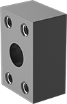
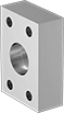
SAE High-Pressure Iron and Steel Unthreaded Pipe Flanges
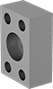 |  |
Front | Back (O-Ring Groove) |
Dash Size | Bolt Hole | ||||||||||||
|---|---|---|---|---|---|---|---|---|---|---|---|---|---|
Pipe Size (A) | SAE Pipe Flange Size (B) | (A) | (B) | Flanged Connection Surface (B) | For Bolt Dia. | Dia. | No. Of | Material | Max. Pressure @ Temp. | Each | |||
Socket-Connect Female | |||||||||||||
| 3/4 | 3/4 | 12 | 12 | Flat | 3/8" | 0.41" | 4 | Steel | 3,000 psi @ 72° F | 2125N34 | 000000 | ||
| 3/4 | 3/4 | 12 | 12 | O-Ring Groove | 3/8" | 0.41" | 4 | Steel | 3,000 psi @ 72° F | 2125N38 | 00000 | ||
| 1 | 1 | 16 | 16 | Flat | 3/8" | 0.41" | 4 | Steel | 3,000 psi @ 72° F | 2125N35 | 00000 | ||
| 1 | 1 | 16 | 16 | O-Ring Groove | 3/8" | 0.41" | 4 | Steel | 3,000 psi @ 72° F | 2125N39 | 00000 | ||
| 1 1/2 | 1 1/2 | 24 | 24 | Flat | 1/2" | 1/2" | 4 | Steel | 3,000 psi @ 72° F | 2125N36 | 00000 | ||
| 1 1/2 | 1 1/2 | 24 | 24 | O-Ring Groove | 1/2" | 0.53" | 4 | Steel | 3,000 psi @ 72° F | 2125N4 | 00000 | ||
| 1 1/2 | 1 1/2 | 24 | 24 | O-Ring Groove | 12 mm | 13 mm | 4 | Steel | 3,000 psi @ 72° F | 2125N44 | 00000 | ||
| 2 | 2 | 32 | 32 | Flat | 1/2" | 0.53" | 4 | Steel | 3,000 psi @ 72° F | 2125N37 | 00000 | ||
| 2 | 2 | 32 | 32 | O-Ring Groove | 1/2" | 0.53" | 4 | Steel | 3,000 psi @ 72° F | 2125N41 | 00000 | ||
| 2 | 2 | 32 | 32 | O-Ring Groove | 12 mm | 13 mm | 4 | Steel | 3,000 psi @ 72° F | 2125N45 | 00000 | ||
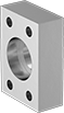
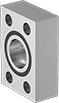
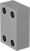 |  |
Front | Back (O-Ring Groove) |
Bolt Hole | |||||||||||
|---|---|---|---|---|---|---|---|---|---|---|---|
SAE Pipe Flange Size | Dash Size | Flanged Connection Surface | For Bolt Dia. | Dia. | No. Of | Material | Max. Pressure @ Temp. | Each | |||
Flanged | |||||||||||
| 3/4 | 12 | O-Ring Groove | 3/8" | 0.41" | 4 | Steel | 3,000 psi @ 72° F | 2125N5 | 000000 | ||
| 1 | 16 | Flat | 3/8" | 0.41" | 4 | Steel | 3,000 psi @ 72° F | 2125N47 | 00000 | ||
| 1 | 16 | O-Ring Groove | 3/8" | 0.41" | 4 | Steel | 3,000 psi @ 72° F | 2125N51 | 00000 | ||
| 1 1/2 | 24 | Flat | 1/2" | 1/2" | 4 | Steel | 3,000 psi @ 72° F | 2125N48 | 00000 | ||
| 1 1/2 | 24 | O-Ring Groove | 1/2" | 0.53" | 4 | Steel | 3,000 psi @ 72° F | 2125N52 | 00000 | ||
| 2 | 32 | O-Ring Groove | 1/2" | 0.53" | 4 | Steel | 3,000 psi @ 72° F | 2125N53 | 00000 | ||
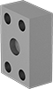
SAE High-Pressure Iron and Steel Threaded Pipe Flanges
 |  |  |
Front | Back (Flat) | Back (O-Ring Groove) |
Dash Size | Bolt Hole | |||||||||||||
|---|---|---|---|---|---|---|---|---|---|---|---|---|---|---|
Pipe Size (A) | Thread Size (A) | SAE Pipe Flange Size (B) | (A) | (B) | Flanged Connection Surface (B) | For Bolt Dia. | Dia. | No. Of | Material | Max. Pressure @ Temp. | Each | |||
NPTF Female | ||||||||||||||
| 3/4 | — | 3/4 | 12 | 12 | Flat | 3/8" | 3/8" | 4 | Steel | 3,000 psi @ 72° F | 2125N1 | 000000 | ||
| 3/4 | — | 3/4 | 12 | 12 | O-Ring Groove | 3/8" | 0.41" | 4 | Steel | 3,000 psi @ 72° F | 2125N14 | 00000 | ||
| 1 | — | 1 | 16 | 16 | Flat | 3/8" | 3/8" | 4 | Steel | 3,000 psi @ 72° F | 2125N11 | 00000 | ||
| 1 | — | 1 | 16 | 16 | O-Ring Groove | 3/8" | 0.41" | 4 | Steel | 3,000 psi @ 72° F | 2125N15 | 00000 | ||
| 1 | — | 1 | 16 | 16 | O-Ring Groove | 10 mm | 10.5 mm | 4 | Steel | 3,000 psi @ 72° F | 2125N19 | 00000 | ||
| 1 1/2 | — | 1 1/2 | 24 | 24 | Flat | 1/2" | 1/2" | 4 | Steel | 3,000 psi @ 72° F | 2125N12 | 00000 | ||
| 1 1/2 | — | 1 1/2 | 24 | 24 | O-Ring Groove | 1/2" | 0.53" | 4 | Steel | 3,000 psi @ 72° F | 2125N16 | 00000 | ||
| 2 | — | 2 | 32 | 32 | Flat | 1/2" | 1/2" | 4 | Steel | 3,000 psi @ 72° F | 2125N13 | 00000 | ||
| 2 | — | 2 | 32 | 32 | O-Ring Groove | 1/2" | 0.53" | 4 | Steel | 3,000 psi @ 72° F | 2125N17 | 00000 | ||
| 2 | — | 2 | 32 | 32 | O-Ring Groove | 12 mm | 13.3 mm | 4 | Steel | 3,000 psi @ 72° F | 2125N21 | 00000 | ||
UN/UNF (SAE Straight) Female | ||||||||||||||
| — | 1 5/16"-12 | 1 | 16 | 16 | O-Ring Groove | 3/8" | 0.41" | 4 | Steel | 3,000 psi @ 72° F | 2125N27 | 00000 | ||
| — | 1 7/8"-12 | 1 1/2 | 24 | 24 | Flat | 1/2" | 1/2" | 4 | Steel | 3,000 psi @ 72° F | 2125N24 | 00000 | ||
| — | 1 7/8"-12 | 1 1/2 | 24 | 24 | O-Ring Groove | 12 mm | 13 mm | 4 | Steel | 3,000 psi @ 72° F | 2125N32 | 00000 | ||
| — | 1 7/8"-12 | 2 | 24 | 32 | O-Ring Groove | 1/2" | 0.53" | 4 | Steel | 3,000 psi @ 72° F | 2125N29 | 00000 | ||
SAE High-Pressure Stainless Steel Unthreaded Pipe Flanges
 |  |  |  |
Flat Front | Flat Back | O-Ring Groove Front | O-Ring Groove Back |
Dash Size | Bolt Hole | 316/316L Stainless Steel | ||||||||||
|---|---|---|---|---|---|---|---|---|---|---|---|---|
Pipe Size (A) | SAE Pipe Flange Size (B) | (A) | (B) | Flanged Connection Surface (B) | For Bolt Dia. | Dia. | No. Of | Max. Pressure @ Temp. | Each | |||
Socket-Connect Female | ||||||||||||
| 3/4 | 3/4 | 12 | 12 | Flat | 3/8" | 0.406" | 4 | 5,000 psi @ 72° F | 1431N11 | 0000000 | ||
| 3/4 | 3/4 | 12 | 12 | O-Ring Groove | 3/8" | 0.406" | 4 | 5,000 psi @ 72° F | 1431N015 | 000000 | ||
| 1 | 1 | 16 | 16 | Flat | 3/8" | 0.406" | 4 | 5,000 psi @ 72° F | 1431N012 | 000000 | ||
| 1 | 1 | 16 | 16 | O-Ring Groove | 3/8" | 0.406" | 4 | 5,000 psi @ 72° F | 1431N016 | 000000 | ||
| 1 1/2 | 1 1/2 | 24 | 24 | Flat | 1/2" | 0.531" | 4 | 3,000 psi @ 72° F | 1431N013 | 000000 | ||
| 1 1/2 | 1 1/2 | 24 | 24 | O-Ring Groove | 1/2" | 0.531" | 4 | 3,000 psi @ 72° F | 1431N017 | 000000 | ||
| 2 | 2 | 32 | 32 | Flat | 1/2" | 0.531" | 4 | 3,000 psi @ 72° F | 1431N014 | 000000 | ||
| 2 | 2 | 32 | 32 | O-Ring Groove | 1/2" | 0.531" | 4 | 3,000 psi @ 72° F | 1431N018 | 000000 | ||
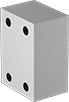


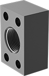
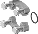
SAE Extreme-Pressure Iron and Steel Threaded Two-Piece Pipe Flanges
 |
Flange |
Bolt Hole | |||||||||||
|---|---|---|---|---|---|---|---|---|---|---|---|
SAE Pipe Flange Size | Dash Size | Flanged Connection Surface | For Bolt Dia. | Dia. | No. Of | Material | Max. Pressure @ Temp. | Each | |||
Flanged | |||||||||||
| 3/4 | 12 | O-Ring Groove | 3/8" | 0.41" | 4 | Steel | 6,000 psi @ 72° F | 2125N66 | 000000 | ||
| 3/4 | 12 | O-Ring Groove | 10 mm | 11 mm | 4 | Steel | 6,000 psi @ 72° F | 2125N71 | 00000 | ||
| 1 | 16 | O-Ring Groove | 0.438" | 0.47" | 4 | Steel | 6,000 psi @ 72° F | 2125N67 | 00000 | ||
| 1 | 16 | O-Ring Groove | 12 mm | 13 mm | 4 | Steel | 6,000 psi @ 72° F | 2125N72 | 00000 | ||
| 1 1/2 | 24 | O-Ring Groove | 5/8" | 0.66" | 4 | Steel | 6,000 psi @ 72° F | 2125N68 | 00000 | ||
| 1 1/2 | 24 | O-Ring Groove | 16 mm | 17 mm | 4 | Steel | 6,000 psi @ 72° F | 2125N7 | 00000 | ||
| 2 | 32 | O-Ring Groove | 3/4" | 0.78" | 4 | Steel | 6,000 psi @ 72° F | 2125N69 | 000000 | ||
| 2 | 32 | O-Ring Groove | 20 mm | 21 mm | 4 | Steel | 6,000 psi @ 72° F | 2125N73 | 000000 | ||
|
Flange |
%20--%3e%3cg%3e%3cg%20id='Layer_1'%3e%3cpath%20class='cls-1'%20d='M68,27.2c-14.6,0-26.4,11.7-26.4,26.3,0,7,2.8,13.7,7.7,18.7v44.8l18.8-16.1,18.7,16.1v-44.9c10.3-10.3,10.3-27,0-37.3-5-4.9-11.7-7.7-18.7-7.7h0ZM81.3,105l-13.2-11.4-13.2,11.4v-28.7c8.2,4.8,18.3,4.8,26.5,0v28.7ZM76.2,70.8c-5.2,2.5-11.2,2.5-16.4,0-9.5-4.5-13.5-15.9-9-25.4,4.5-9.5,15.9-13.5,25.4-9,9.5,4.5,13.5,15.9,9,25.4-1.9,4-5.1,7.1-9,9Z'/%3e%3cpath%20class='cls-2'%20d='M5.8,95.5c-1.2,0-2.1-1-2.1-2.1,0,0,0,0,0,0V29.4h20.9c2.1,0,3.8-1.7,3.8-3.8V3.7c.2,0,.4,0,.5,0h37.5c1.2,0,2.1,1,2.1,2.1v18.6c1.2,0,2.5.1,3.7.3V5.8C72.2,2.6,69.6,0,66.4,0H28.9c-1.5,0-3,.6-4.1,1.7h-.1c0,.1-23,23.2-23,23.2-1.1,1.1-1.7,2.6-1.7,4.1v64.3c0,3.2,2.6,5.8,5.8,5.8h41.7v-3.7H5.8ZM24.7,7.1v18.7H6L24.7,7.1Z'/%3e%3c/g%3e%3c/g%3e%3c/svg%3e)
Pipe Size (A) | For SAE Pipe Flange Size (B) | Dash Size (A) | For Flanged Connection Surface | Material | Max. Pressure @ Temp. | Each | |||
|---|---|---|---|---|---|---|---|---|---|
NPTF Female | |||||||||
| 3/4 | 3/4 | 12 | O-Ring Groove | Steel | 6,000 psi @ 72° F | 2125N86 | 000000 | ||
| 1 | 1 | 16 | O-Ring Groove | Steel | 6,000 psi @ 72° F | 2125N87 | 00000 | ||
| 1 1/2 | 1 1/2 | 24 | O-Ring Groove | Steel | 6,000 psi @ 72° F | 2125N88 | 000000 | ||
| 2 | 2 | 32 | O-Ring Groove | Steel | 6,000 psi @ 72° F | 2125N89 | 000000 | ||
SAE High-Pressure Stainless Steel Threaded Pipe Flanges
 |  |  |  |
Flat Front | Flat Back | O-Ring Groove Front | O-Ring Groove Back |
Dash Size | Bolt Hole | 316/316L Stainless Steel | |||||||||||
|---|---|---|---|---|---|---|---|---|---|---|---|---|---|
Pipe Size (A) | Thread Size (A) | SAE Pipe Flange Size (B) | (A) | (B) | Flanged Connection Surface (B) | For Bolt Dia. | Dia. | No. Of | Max. Pressure @ Temp. | Each | |||
NPTF Female | |||||||||||||
| 3/4 | — | 3/4 | 12 | 12 | O-Ring Groove | 3/8" | 0.406" | 4 | 2,500 psi @ 72° F | 1723N15 | 0000000 | ||
| 1 | — | 1 | 16 | 16 | Flat | 3/8" | 0.312" | 4 | 2,000 psi @ 72° F | 1723N12 | 000000 | ||
| 1 | — | 1 | 16 | 16 | O-Ring Groove | 3/8" | 0.406" | 4 | 2,000 psi @ 72° F | 1723N16 | 000000 | ||
| 1 1/2 | — | 1 1/2 | 24 | 24 | Flat | 1/2" | 0.422" | 4 | 1,000 psi @ 72° F | 1723N13 | 000000 | ||
| 1 1/2 | — | 1 1/2 | 24 | 24 | O-Ring Groove | 1/2" | 0.531" | 4 | 1,000 psi @ 72° F | 1723N17 | 000000 | ||
| 2 | — | 2 | 32 | 32 | Flat | 1/2" | 0.422" | 4 | 1,000 psi @ 72° F | 1723N14 | 000000 | ||
| 2 | — | 2 | 32 | 32 | O-Ring Groove | 1/2" | 0.531" | 4 | 1,000 psi @ 72° F | 1723N18 | 000000 | ||
UN/UNF (SAE Straight) Female | |||||||||||||
| — | 1 5/16"-12 | 1 | 16 | 16 | O-Ring Groove | 3/8" | 0.406" | 4 | 6,000 psi @ 72° F | 1723N29 | 000000 | ||
| — | 2 1/2"-12 | 2 | 32 | 32 | Flat | 1/2" | 0.531" | 4 | 3,000 psi @ 72° F | 1723N27 | 000000 | ||
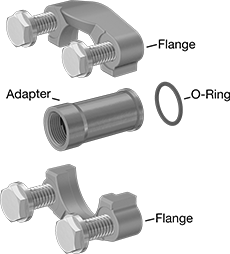
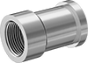
SAE High-Pressure Stainless Steel Threaded Two-Piece Pipe Flanges
 |
Flanged O-Ring Groove |
Bolt Hole | 316/316L Stainless Steel | |||||||||
|---|---|---|---|---|---|---|---|---|---|---|
SAE Pipe Flange Size | Dash Size | Flanged Connection Surface | For Bolt Dia. | Dia. | No. Of | Max. Pressure @ Temp. | Each | |||
Flanged | ||||||||||
| 3/4 | 12 | O-Ring Groove | 3/8" | 0.406" | 4 | 5,000 psi @ 72° F | 1723N37 | 0000000 | ||
| 3/4 | 12 | O-Ring Groove | 10 mm | 10 mm | 4 | 5,000 psi @ 72° F | 1723N42 | 000000 | ||
| 1 | 16 | O-Ring Groove | 3/8" | 0.406" | 4 | 4,600 psi @ 72° F | 1723N38 | 000000 | ||
| 1 | 16 | O-Ring Groove | 10 mm | 10 mm | 4 | 4,600 psi @ 72° F | 1723N43 | 000000 | ||
| 1 1/2 | 24 | O-Ring Groove | 1/2" | 0.531" | 4 | 3,000 psi @ 72° F | 1723N39 | 000000 | ||
| 1 1/2 | 24 | O-Ring Groove | 12 mm | 13 mm | 4 | 3,000 psi @ 72° F | 1723N44 | 000000 | ||
| 2 | 32 | O-Ring Groove | 1/2" | 0.531" | 4 | 3,000 psi @ 72° F | 1723N41 | 000000 | ||
| 2 | 32 | O-Ring Groove | 12 mm | 13 mm | 4 | 3,000 psi @ 72° F | 1723N45 | 000000 | ||
 | 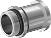 |
Female | Male |
316/316L Stainless Steel | |||||||||
|---|---|---|---|---|---|---|---|---|---|
Pipe Size (A) | Thread Size (A) | For SAE Pipe Flange Size (B) | Dash Size (A) | For Flanged Connection Surface | Max. Pressure @ Temp. | Each | |||
NPTF Female | |||||||||
| 3/4 | — | 3/4 | 12 | O-Ring Groove | 5,000 psi @ 72° F | 1723N51 | 0000000 | ||
| 1 | — | 1 | 16 | O-Ring Groove | 4,600 psi @ 72° F | 1723N52 | 000000 | ||
| 1 1/2 | — | 1 1/2 | 24 | O-Ring Groove | 3,000 psi @ 72° F | 1723N53 | 000000 | ||
| 2 | — | 2 | 32 | O-Ring Groove | 3,000 psi @ 72° F | 1723N54 | 000000 | ||
UN/UNF (SAE Straight) Male | |||||||||
| — | 1 5/16"-12 | 1 | 16 | O-Ring Groove | 4,600 psi @ 72° F | 1723N47 | 000000 | ||
| — | 1 7/8"-12 | 1 1/2 | 24 | O-Ring Groove | 3,000 psi @ 72° F | 1723N48 | 000000 | ||
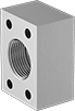
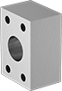
SAE High-Pressure Iron and Steel Threaded Two-Piece Pipe Flanges
|
Flange |
Bolt Hole | |||||||||||
|---|---|---|---|---|---|---|---|---|---|---|---|
SAE Pipe Flange Size | Dash Size | Flanged Connection Surface | For Bolt Dia. | Dia. | No. Of | Material | Max. Pressure @ Temp. | Each | |||
Flanged | |||||||||||
| 1 | 16 | O-Ring Groove | 3/8" | 0.41" | 4 | Steel | 3,000 psi @ 72° F | 2125N59 | 000000 | ||
| 1 | 16 | O-Ring Groove | 10 mm | 11 mm | 4 | Steel | 3,000 psi @ 72° F | 2125N63 | 00000 | ||
| 1 1/2 | 24 | O-Ring Groove | 1/2" | 0.53" | 4 | Steel | 3,000 psi @ 72° F | 2125N6 | 00000 | ||
| 1 1/2 | 24 | O-Ring Groove | 12 mm | 13 mm | 4 | Steel | 3,000 psi @ 72° F | 2125N64 | 00000 | ||
| 2 | 32 | O-Ring Groove | 1/2" | 0.53" | 4 | Steel | 3,000 psi @ 72° F | 2125N61 | 00000 | ||
| 2 | 32 | O-Ring Groove | 12 mm | 13 mm | 4 | Steel | 3,000 psi @ 72° F | 2125N65 | 00000 | ||
